Nonlinear Optics - Chapter 2 pps
Bạn đang xem bản rút gọn của tài liệu. Xem và tải ngay bản đầy đủ của tài liệu tại đây (671.04 KB, 65 trang )
Chapter 2
Wave-Equation Description of
Nonlinear Optical Interactions
2.1. The Wave Equation for Nonlinear Optical Media
We have seen in the last chapter how nonlinearity in the response of a material
system to an intense laser field can cause the polarization of the medium to
develop new frequency components not present in the incident radiation field.
These new frequency components of the polarization act as sources of new
frequency components of the electromagnetic field. In the present chapter,
we examine how Maxwell’s equations describe the generation of these new
components of the field, and more generally we see how the various frequency
components of the field become coupled by the nonlinear interaction.
Before developing the mathematical theory of these effects, we shall give
a simple physical picture o f how these frequency components are generated.
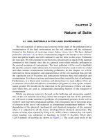
For definiteness, we consider the case of sum-frequency generation as shown
in part (a) of Fig. 2.1.1, where the input fields are at frequencies ω
1
and ω
2
.
Because of nonlinearities in the atomic response, each atom develops an os-
cillating dipole moment which contains a component at frequency ω
1
+ ω
2
.
An isolated atom would radiate at this frequency in the form of a dipole ra-
diation pattern, as shown symbolically in part (b) of the figure. However, any
material sample contains an enormous number N of atomic dipoles, each os-
cillating w ith a phase that is determined by the phases of the incident fields.
If the relative phasing of these dipoles is correct, the field radiated by each
dipole will add constructively in the forward direction, leading to radiation in
the form of a well-defined beam, as illustrated in part ( c) of the figure. The
system will act as a phased array of dipoles when a certain condition, known
as the phase-matching condition (see Eq. (2.2.14) in the next section), is satis-
69
70 2
♦
Wave-Equation Description of Nonlinear Optical Interactions
FIGURE 2.1.1 Sum-frequency generation.
fied. Under these conditions, the electric field strength of the radiation emitted
in the forward direction will be N times larger than that due to any one atom,
and consequently the intensity will be N
2
times as large.
Let us now consider the form of the wave equation for the propagation of
light through a nonlinear optical medium. We begin with Maxwell’s equa-
tions, which we write in SI units in the form
∗
∇·
˜
D =˜ρ, (2.1.1)
∇·
˜
B = 0, (2.1.2)
∇×
˜
E =−
∂
˜
B
∂t
, (2.1.3)
∇×
˜
H =
∂
˜
D
∂t
+
˜
J. (2.1.4)
We are primarily interested in the solution of these equations in regions of
space that contain no free charges, so that
˜ρ =0, (2.1.5)
∗
Throughout the text we use a tilde (
˜
) to denote a quantity that varies rapidly in time.
2.1. The Wave Equation for Nonlinear Optical Media 71
and that contain no free currents, so that
˜
J = 0. (2.1.6)
We also assume that the material is nonmagnetic, so that
˜
B = μ
0
˜
H. (2.1.7)
However, we allow the material to be nonlinear in the sense that the fields
˜
D
and
˜
E are related by
˜
D =
0
˜
E +
˜
P, (2.1.8)
where in general the polarization vector
˜
P depends nonlinearly upon the local
value of the electric field strength
˜
E.
We now proceed to derive the optical wave equation in the usual manner.
We take the curl of the curl-
˜
E Maxwell equation (2.1.3), interchange the order
of space and time derivatives on the right-hand side of the resulting equation,
and u se Eqs. (2.1.4), (2.1.6), and (2.1.7) to replace ∇×
˜
B by μ
0
(∂
˜
D/∂t),to
obtain the equation
∇×∇×
˜
E +μ
0
∂
2
∂t
2
˜
D = 0. (2.1.9a)
We now use Eq. (2.1.8) to eliminate
˜
D from this equation, and we thereby
obtain the expression
∇×∇×
˜
E +
1
c
2
∂
2
∂t
2
˜
E =−
1
0
c
2
∂
2
˜
P
∂t
2
. (2.1.9b)
On the right-hand side of this equation we have replaced μ
0
by 1/
0
c
2
for
future convenience.
This is the most general form of the wave equation in nonlinear optics.
Under certain conditions it can be simplified. For example, by using an iden-
tity from vector calculus, we can write the first term on the left-hand side of
Eq. (2.1.9b) as
∇×∇×
˜
E =∇
∇·
˜
E
−∇
2
˜
E. (2.1.10)
In the linear optics of isotropic source-free media, the first term on the right-
hand side of this equation vanishes because the Maxwell equation ∇·
˜
D = 0
implies that ∇·
˜
E = 0 . However, in nonlinear optics this term is generally
nonvanishing even for isotropic materials, as a consequence of the more gen-
eral relation (2.1.8) between
˜
D and
˜
E. Fortunately, in nonlinear optics the first
term on the right-hand side of Eq. (2.1.10) can usually be dropped for cases of
interest. For example, if
˜
E is of the form of a transverse, infinite plane wave,
72 2
♦
Wave-Equation Description of Nonlinear Optical Interactions
∇·
˜
E vanishes identically. More generally, t he first term can often be shown to
be small, even when it does not vanish identically, especially when the slowly
varying amplitude approximation (see Section 2.2) is valid. For the remain-
der of this book, we shall usually assume that the contribution of ∇(∇·
˜
E) in
Eq. (2.1.10) is negligible so that the wave equation can be taken to have the
form
∇
2
˜
E −
1
c
2
∂
2
∂t
2
˜
E =
1
0
c
2
∂
2
˜
P
∂t
2
. (2.1.11)
Alternatively, the wave equation can be expressed as
∇
2
˜
E −
1
0
c
2
∂
2
∂t
2
˜
D = 0 (2.1.12)
where
˜
D =
0
˜
E +
˜
P.
It is often convenient to split
˜
P into its linear and nonlinear parts as
˜
P =
˜
P
(1)
+
˜
P
NL
. (2.1.13)
Here
˜
P
(1)
is the part of
˜
P that depends linearly on the electric field strength
˜
E.
We can similarly decompose the displacement field
˜
D into its linear and non-
linear parts as
˜
D =
˜
D
(1)
+
˜
P
NL
, (2.1.14a)
where the linear part is given by
˜
D
(1)
=
0
˜
E +
˜
P
(1)
. (2.1.14b)
In terms of this quantity, the wave equation (2.1.11) can be written as
∇
2
˜
E −
1
0
c
2
∂
2
˜
D
(1)
∂t
2
=
1
0
c
2
∂
2
˜
P
NL
∂t
2
. (2.1.15)
To see why this form of the wave equation is useful, let us first consider the
case of a lossless, dispersionless medium. We can then express the relation
between
˜
D
(1)
and
˜
E in terms of a real, frequency-independent dielectric tensor
(1)
as
˜
D
(1)
=
0
(1)
·
˜
E. (2.1.16a)
For the case of an isotropic material, this relation reduces to simply
˜
D
(1)
=
0
(1)
˜
E, (2.1.16b)
where
(1)
is a scalar quantity. Note that we are using the convention that
0
=
8.85 × 10
−12
F/m is a fundamental constant, the permittivity of free space,
2.1. The Wave Equation for Nonlinear Optical Media 73
whereas
(1)
is the dimensionless, relative permittivity which is different for
each material. For this (simpler) case of an isotropic, dispersionless material,
the wave equation (2.1.15) becomes
−∇
2
˜
E +
(1)
c
2
∂
2
˜
E
∂t
2
=−
1
0
c
2
∂
2
˜
P
NL
∂t
2
. (2.1.17)
This equation has the form of a driven (i.e., inhomogeneous) wave equation;
the nonlinear response of the medium acts as a source term which appears
on the right-hand side of this equation. In the absence of this source term,
Eq. (2.1.17) admits solutions of the form of free waves propagating with
velocity c/n, where n is the (linear) index of refraction that satisfies n
2
=
(1)
.
For the case of a dispersive medium, we must consider each frequency com-
ponent of the field separately. We represent the electric, linear displacement,
and polarization fields as the sums of their various frequency components:
˜
E(r,t)=
n
˜
E
n
(r,t), (2.1.18a)
˜
D
(1)
(r,t)=
n
˜
D
(1)
n
(r,t), (2.1.18b)
˜
P
NL
(r,t)=
n
˜
P
NL
n
(r,t), (2.1.18c)
where the summation is to be performed over positive field frequencies only,
and we represent each frequency component in terms of its complex amplitude
as
˜
E
n
(r,t)=E
n
(r)e
−iω
n
t
+c.c., (2.1.19a)
˜
D
(1)
n
(r,t)=D
(1)
n
(r)e
−iω
n
t
+c.c., (2.1.19b)
˜
P
NL
n
(r,t)=P
NL
n
(r)e
−iω
n
t
+c.c. (2.1.19c)
If dissipation can be neglected, the relationship between
˜
D
(1)
n
and
˜
E
n
can be
expressed in terms of a real, frequency-dependent dielectric tensor accord-
ing to
˜
D
(1)
n
(r,t)=
0
(1)
(ω
n
) ·
˜
E
n
(r,t). (2.1.20)
When Eqs. (2.1.18a) through (2.1.20) are introduced into Eq. (2.1.15), we
obtain a wave equation analogous to (2.1.17) that is valid for each frequency
component of the field:
∇
2
˜
E
n
−
(1)
(ω
n
)
c
2
∂
2
˜
E
n
∂t
2
=
1
0
c
2
∂
2
˜
P
NL
n
∂t
2
. (2.1.21)
74 2
♦
Wave-Equation Description of Nonlinear Optical Interactions
The general case of a dissipative medium is treated by allowing the dielec-
tric tensor to be a complex quantity that relates the complex field amplitudes
according to
D
(1)
n
(r) =
0
(1)
(ω
n
) ·E
n
(r). (2.1.22)
This expression, along with Eqs. (2.1.17) and (2.1.18), can be introduced into
the wave equation (2.1.15), to obtain
∇
2
E
n
(r) +
ω
2
n
c
2
(1)
(ω
n
) ·E
n
(r) =−
ω
2
n
0
c
2
P
NL
n
(r). (2.1.23)
2.2. The Coupled-Wave Equations for Sum-Frequency
Generation
We next study how the nonlinear optical wave equation that we derived
in the previous section can be used to describe specific nonlinear optical
interactions. In particular, we consider sum-frequency generation in a lossless
nonlinear optical medium involving collimated, monochromatic, continuous-
wave input beams. We assume the configuration shown in Fig. 2.2.1, where
the applied waves fall onto the nonlinear medium at normal incidence. For
simplicity, we ignore double refraction effects. The treatment given here can
be generalized straightforwardly to include nonnormal incidence and double
refraction.
∗
The wave equation in Eq. (2.1.21) must hold for each frequency component
of the field and in particular for the sum-frequency component at frequency
ω
3
. In the absence of a nonlinear source term, the solution to this equation for
a plane wave at frequency ω
3
propagating in the +z direction is
˜
E
3
(z, t) = A
3
e
i(k
3
z−ω
3
t)
+c.c., (2.2.1)
FIGURE 2.2.1 Sum-frequency generation.
∗
See, for example, Shen (1984, Chapter 6).
2.2. The Coupled-Wave Equations for Sum-FrequencyGeneration 75
where
∗
k
3
=
n
3
ω
3
c
,n
2
3
=
(1)
(ω
3
), (2.2.2)
and where the amplitude of the wave A
3
is a constant. We expect on physical
grounds that, when the nonlinear source term is not too large, the solution to
Eq. (2.1.21) will still be of the form of Eq. (2.2.1), except that A
3
will become
a slowly varying function of z. We hence adopt Eq. (2.2.1) with A
3
taken to be
a function of z as the form of the trial solution to the wave equation (2.1.21)
in the presence of the nonlinear source term.
We represent the nonlinear source term appearing in Eq. (2.1.21) as
˜
P
3
(z, t) = P
3
e
−iω
3
t
+c.c., (2.2.3)
where according to Eq. (1.5.28)
P
3
=4
0
d
eff
E
1
E
2
. (2.2.4)
We represent the applied fields (i = 1, 2) as
˜
E
i
(z, t) = E
i
e
−iω
i
t
+c.c., where E
i
=A
i
e
ik
i
z
. (2.2.5)
The amplitude of the nonlinear polarization can then be written as
P
3
=4
0
d
eff
A
1
A
2
e
i(k
1
+k
2
)z
≡p
3
e
i(k
1
+k
2
)z
. (2.2.6)
We now substitute Eqs. (2.2.1), (2.2.3), and (2.2.6) into the wave equation
(2.1.21). Since the fields depend only on the longitudinal coordinate z, we can
replace ∇
2
by d
2
/dz
2
. We then obtain
d
2
A
3
dz
2
+2ik
3
dA
3
dz
−k
2
3
A
3
+
(1)
(ω
3
)ω
2
3
A
3
c
2
e
i(k
3
z−ω
3
t)
+c.c.
=
−4d
eff
ω
2
3
c
2
A
1
A
2
e
i[(k
1
+k
2
)z−ω
3
t]
+c.c. (2.2.7)
Since k
2
3
=
(1)
(ω
3
)ω
2
3
/c
2
, the third and fourth terms on the left-hand side of
this expression cancel. Note that we can drop the complex conjugate terms
from each side and still maintain the equality. We can then cancel the factor
exp(−iω
3
t) on each side and write the resulting equation as
d
2
A
3
dz
2
+2ik
3
dA
3
dz
=
−4d
eff
ω
2
3
c
2
A
1
A
2
e
i(k
1
+k
2
−k
3
)z
. (2.2.8)
∗
For convenience, we are working in the scalar field approximation; n
3
represents the refractive
index appropriate to the state of polarization of the ω
3
wave.
76 2
♦
Wave-Equation Description of Nonlinear Optical Interactions
It is usually permissible to neglect the first term on the left-hand side of this
equation on the grounds that it is very much smaller than the second. This
approximation is known as the slowly varying amplitude approximation and
is valid whenever
d
2
A
3
dz
2
k
3
dA
3
dz
. (2.2.9)
This condition requires that the fractional change in A
3
in a distance of the
order of an optical wavelength must be much smaller than unity. When this
approximation is made, Eq. (2.2.8) becomes
dA
3
dz
=
2id
eff
ω
2
3
k
3
c
2
A
1
A
2
e
ikz
, (2.2.10)
where we have introduced the quantity
k = k
1
+k
2
−k
3
, (2.2.11)
which is called the wavevector (or momentum) mismatch. Equation (2.2.10) is
known as a coupled-amplitude equation, because it shows how the amplitude
of the ω
3
wave varies as a consequence of its coupling to the ω
1
and ω
2
waves.
In general, the spatial variation of the ω
1
and ω
2
waves must also be taken
into consideration, and we can derive analogous equations for the ω
1
and ω
2
fields by repeating the derivation given above for each of these frequencies.
We hence find two additional coupled-amplitude equations given by
dA
1
dz
=
2id
eff
ω
2
1
k
1
c
2
A
3
A
∗
2
e
−ikz
, (2.2.12a)
dA
2
dz
=
2id
eff
ω
2
2
k
2
c
2
A
3
A
∗
1
e
−ikz
. (2.2.12b)
Note that, in writing these equations in the forms shown, we have assumed
that the medium is lossless. For a lossless medium, no explicit loss terms
need be included in these equations, and furthermore we can make use of
the condition of full permutation symmetry (Eq. (1.5.8)) to conclude that the
coupling coefficient has the same value d
eff
in each equation.
For future reference, we note that Eq. (2.2.10) can be written more generally
in terms of the slowly varying amplitude p
3
of the nonlinear polarization as
dA
3
dz
=
iω
3
2
0
n
3
c
p
3
e
ikz
, (2.2.13)
2.2. The Coupled-Wave Equations for Sum-FrequencyGeneration 77
where according to Eq. (2.2.6) p
3
is given by P
3
=p
3
exp[i(k
1
+k
2
)z]. Anal-
ogous equations can be written of course for the spatial variations of A
1
and A
2
.
2.2.1. Phase-Matching Considerations
For simplicity, let us first assume that the amplitudes A
1
and A
2
of the input
fields can be taken as constants on the right-hand side of Eq. (2.2.10). This
assumption is valid whenever the conversion of the input fields into the sum-
frequency field is not too large. We note that, for the special case
k = 0, (2.2.14)
the amplitude A
3
of the sum-frequency wave increases linearly with z,and
consequently that its intensity increases quadratically with z. The condition
(2.2.14) is known as the condition of perfect phase matching. When this con-
dition is fulfilled, the generated wave maintains a fixed phase relation with
respect to the nonlinear polarization and is able to extract energy most ef-
ficiently from the incident waves. From a microscopic point of view, when
the condition (2.2.14) is fulfilled the individual atomic dipoles that constitute
the material system are properly phased so that the field emitted by each di-
pole adds coherently in the forward direction. The total power radiated by the
ensemble of atomic dipoles thus scales as the square of the number of atoms
that participate.
When the condition (2.2.14) is not satisfied, the intensity of the emit-
ted radiation is smaller than for the case of k = 0. The amplitude of the
sum-frequency (ω
3
) field at the exit plane of the nonlinear medium is given
in this case by integrating Eq. (2.2.10) from z = 0toz = L, yielding
A
3
(L) =
2id
eff
ω
2
3
A
1
A
2
k
3
c
2
L
0
e
ikz
dz =
2id
eff
ω
2
3
A
1
A
2
k
3
c
2
e
ikL
−1
ik
.
(2.2.15)
The intensity of the ω
3
wave is given by the magnitude of the time-averaged
Poynting vector, which for our definition of field amplitude is given by
I
i
=2n
i
0
c|A
i
|
2
,i=1, 2, 3. (2.2.16)
We thus obtain
I
3
=
8n
3
0
d
2
eff
ω
4
3
|A
1
|
2
|A
2
|
2
k
2
3
c
3
e
ikL
−1
k
2
. (2.2.17)
78 2
♦
Wave-Equation Description of Nonlinear Optical Interactions
The squared modulus that appears in this equation can be expressed as
e
ikL
−1
k
2
= L
2
e
ikL
−1
kL
e
−ikL
−1
kL
=2L
2
(1 −coskL)
(kL)
2
= L
2
sin
2
(kL/2)
(kL/2)
2
≡L
2
sinc
2
(kL/2). (2.2.18)
Finally, our expression for I
3
can be written in terms of the intensities of the
incident fields by using Eq. (2.2.16) to express |A
i
|
2
in terms of the intensities,
yielding the result
I
3
=
8d
2
eff
ω
2
3
I
1
I
2
n
1
n
2
n
3
0
c
2
L
2
sinc
2
kL
2
. (2.2.19)
Note that the effect of wavevector mismatch is included entirely in the factor
sinc
2
(kL/2). This factor, which is known as the phase mismatch factor, is
plotted in Fig. 2.2.2.
It should be noted that the efficiency of the three-wave mixing process
decreases as |k|L increases, with some oscillations occurring. The reason
for this behavior is that if L is greater than approximately 1 /k, the output
wave can get out of phase with its driving polarization, and power can flow
from the ω
3
wave back into the ω
1
and ω
2
waves (see Eq. (2.2.10)). For this
reason, one sometimes defines
L
coh
=2/k (2.2.20)
FIGURE 2.2.2 Effects of wavevector mismatch on the efficiency of sum-frequency
generation.
2.3. Phase Matching 79
to be the coherent buildup length of the interaction, so that the phase mismatch
factor in Eq. (2.2.19) can be written as
sinc
2
(L/L
coh
). (2.2.21)
2.3. Phase Matching
We saw in Section 2.2 that for sum-frequency generation involving undepleted
input beams, the intensity of the generated field at frequency ω
3
= ω
1
+ ω
2
varies with the wavevector mismatch
k = k
1
+k
2
−k
3
(2.3.1)
according to
I
3
=I
(max)
3
sin(kL/2)
(kL/2)
2
. (2.3.2)
This expression predicts a dramatic decrease in the efficiency of the sum-
frequency generation process when the condition of perfect phase matching,
k = 0, is not satisfied.
For nonlinear mixing processes that are sufficiently efficient to lead to de-
pletion of the input beams, the functional dependence of the efficiency of the
process on the phase mismatch is no longer given by Eq. (2.3.2). However,
even in this case the efficient generation of the output field requires that the
condition k = 0 be maintained.
Behavior of the sort predicted by Eq. (2.3.2) was first observed experimen-
tally by Maker et al. (1962) and is illustrated in Fig. 2.3.1. Their experiment
involved focusing the output of a pulsed ruby laser into a single crystal of
quartz and measuring how the intensity of the second-harmonic signal varied
as the crystal was rotated, thus varying the effective path length L through
the crystal. The wavevector mismatch k was nonzero and approximately the
same for all orientations used in their experiment.
The phase-matching condition k = 0 is often difficult to achieve because
the refractive index of materials that are lossless in the range ω
1
to ω
3
(we
assume that ω
1
≤ ω
2
<ω
3
) shows an effect known as normal dispersion: the
refractive index is an increasing function of frequency. As a result, the condi-
tion for perfect phase matching with collinear beams,
n
1
ω
1
c
+
n
2
ω
2
c
=
n
3
ω
3
c
, (2.3.3)
80 2
♦
Wave-Equation Description of Nonlinear Optical Interactions
FIGURE 2.3.1 (a) Experimental setup of Maker et al. (1962). (b) Their experimental
results.
where
ω
1
+ω
2
=ω
3
, (2.3.4)
cannot be achieved. For the case of second-harmonic generation, with ω
1
=
ω
2
, ω
3
=2ω
1
, these conditions require that
n(ω
1
) = n(2ω
1
), (2.3.5)
which is clearly not possible when n(ω) increases monotonically with ω.For
the case of sum-frequency generation, the argument is slightly more compli-
cated, but the conclusion is the same. To show that phase matching is not
possible in this case, we first rewrite Eq. (2.3.3) as
n
3
=
n
1
ω
1
+n
2
ω
2
ω
3
. (2.3.6)
This result is now used to express the refractive index difference n
3
−n
2
as
n
3
−n
2
=
n
1
ω
1
+n
2
ω
2
−n
2
ω
3
ω
3
=
n
1
ω
1
−n
2
(ω
3
−ω
2
)
ω
3
=
n
1
ω
1
−n
2
ω
1
ω
3
,
2.3. Phase Matching 81
or finally as
n
3
−n
2
=(n
1
−n
2
)
ω
1
ω
3
. (2.3.7)
For normal dispersion, n
3
must be greater than n
2
, and hence the left-hand
side of this equation must be positive. However, n
2
must also be greater
than n
1
, showing that the right-hand side must be negative, which demon-
strates that Eq. (2.3.7) cannot possess a solution.
In principle, it is possible to achieve the phase-matching condition by mak-
ing use of anomalous dispersion, that is, the decrease in refractive index with
increasing frequency that occurs near an absorption feature. However, the
most common procedure for achieving phase matching is to make use of the
birefringence displayed by many crystals. Birefringence is the dependence of
the refractive index on the direction of polarization of the optical radiation.
Not all crystals display birefringence; in particular, crystals belonging to the
cubic crystal system are optically isotropic (i.e., show no birefringence) and
thus are not phase-matchable.
The linear optical properties of the various crystal systems are summarized
in Table 2.3.1.
In order to achieve phase matching through the use of birefringent crys-
tals, the highest-frequency wave ω
3
= ω
1
+ ω
2
is polarized in the direction
that gives it the lower of the two possible refractive indices. For the case of
a negative uniaxial crystal, as in the example shown in Fig. 2.3.2, this choice
corresponds to the extraordinary polarization. There are two choices for the
polarizations of the lower-frequency waves. Midwinter and Warner (1965) de-
fine type I phase matching to be the case in which the two lower-frequency
waves have the same polarization, and type II to be the case where the polar-
izations are orthogonal. The possibilities are summarized in Table 2.3.2. No
assumptions regarding the relative sizes of ω
1
and ω
2
are implied by the clas-
sification scheme. However, for type II phase matching it is easier to achieve
the phase-matching condition (i.e., less birefringence is required) if ω
2
>ω
1
for the choice of ω
1
and ω
2
used in writing the table. Also, independent of the
relative values of ω
1
and ω
2
, type I phase matching is easier to achieve than
type II.
Careful control of the refractive indices at each of the three optical frequen-
cies is required in order to achieve the phase-matching condition (k = 0).
Typically phase matching is accomplished by one of two methods: angle tun-
ing and temperature tuning.
Angle Tuning This method involves precise angular orientation of the crystal
with respect to the propagation direction o f the incident light. It is most sim-
82 2
♦
Wave-Equation Description of Nonlinear Optical Interactions
TABLE 2.3.1 Linear optical classification of the various crystal systems
System Linear Optical Classification
Triclinic, monoclinic, orthorhombic Biaxial
Trigonal, tetragonal, hexagonal Uniaxial
Cubic Isotropic
FIGURE 2.3.2 Dispersion of the refractive indices of a negative uniaxial crystal. For
the opposite case of a positive uniaxial crystal, the extraordinary index n
e
is greater
than the ordinary index n
o
.
TABLE 2.3.2 Phase-matching methods for uniaxial crys-
tals
Positive uniaxial Negative uniaxial
(n
e
>n
0
)(n
e
<n
0
)
Type I n
o
3
ω
3
=n
e
1
ω
1
+n
e
2
ω
2
n
e
3
ω
3
=n
o
1
ω
1
+n
o
2
ω
2
Type II n
o
3
ω
3
=n
o
1
ω
1
+n
e
2
ω
2
n
e
3
ω
3
=n
e
1
ω
1
+n
o
2
ω
2
ply described for the case of a uniaxial crystal, and the following discussion
is restricted to this case. Uniaxial crystals are characterized by a particular
direction known as the optic axis (or c axis or z axis). Light polarized per-
pendicular to the plane containing the propagation vector k and the optic axis
is called the ordinary polarization. Such light experiences the ordinary refrac-
tive index n
o
. Light polarized in the plane containing k and the optic axis is
called the extraordinary polarization and experiences a refractive index n
e
(θ)
that depends on the angle θ between the optic axis and k according to the
2.3. Phase Matching 83
FIGURE 2.3.3 Geometry of angle-tuned phase matching of second-harmonic gener-
ation for the case of a negative uniaxial crystal.
relation
∗
1
n
e
(θ)
2
=
sin
2
θ
¯n
2
e
+
cos
2
θ
n
2
o
. (2.3.8)
Here ¯n
e
is the principal value of the extraordinary refractive index. Note that
n
e
(θ) is equal to the principal value ¯n
e
for θ = 90 degrees and is equal to n
o
for θ = 0. Phase matching is achieved by adjusting the angle θ to obtain the
value of n
e
(θ) for which the condition k =0 is satisfied.
As an illustration of angle phase matching, we consider the case of
type I second-harmonic generation in a negative uniaxial crystal, as shown in
Fig. 2.3.3. Since n
e
is less than n
o
for a negative uniaxial crystal, one chooses
the fundamental frequency to propagate as an ordinary wave and the second-
harmonic frequency to propagate as an extraordinary wave, in order that the
birefringence of the material can compensate for the dispersion. The phase-
matching condition (2.3.5) then becomes
n
e
(2ω,θ) =n
o
(ω), (2.3.9)
or
sin
2
θ
¯n
e
(2ω)
2
+
cos
2
θ
n
o
(2ω)
2
=
1
n
o
(ω)
2
. (2.3.10)
In order to simplify this equation, we replace cos
2
θ by 1 − sin
2
θ and solve
for sin
2
θ to obtain
sin
2
θ =
1
n
o
(ω)
2
−
1
n
o
(2ω)
2
1
¯n
e
(2ω)
2
−
1
n
o
(2ω)
2
. (2.3.11)
This equation shows how the crystal should be oriented in order to achieve
the phase-matching condition. Note that this equation does not necessarily
∗
For a derivation of this relation, see, for example, Born and Wolf (1975, Section 14.3), Klein
(1970, Eq. (11.160a)), or Zernike and Midwinter (1973, Eq. (1.26)).
84 2
♦
Wave-Equation Description of Nonlinear Optical Interactions
possess a solution for a physically realizable orientation angle (that is, a real
value of the angle θ). For example, if for some material the dispersion in
the linear refractive index is too large or the birefringence is too small, the
right-hand side of this equation can have a magnitude larger than unity and
consequently the equation will have no solution.
Temperature Tuning There is one serious drawback to the use of angle tuning.
Whenever the angle θ between the propagation direction and the optic axis
has a value other than 0 or 90 degrees, the Poynting vector S and the propaga-
tion vector k are not parallel for extraordinary rays. As a result, ordinary and
extraordinary rays with parallel propagation vectors quickly diverge from one
another as they propagate through the crystal. This walkoff effect limits the
spatial overlap of the two waves and decreases the efficiency of any nonlinear
mixing process involving such waves.
For some crystals, notably lithium niobate, the amount of birefringence is
strongly temperature-dependent. As a result, it is possible to phase-match the
mixing process by holding θ fixed at 90 degrees and varying the temperature
of the crystal. The temperature dependence of the refractive indices of lithium
niobate has been given by Hobden and Warner (1966).
2.4. Quasi-Phase-Matching
Section 2.3 describes techniques that utilize the birefringence of an optical
material to achieve the phase-matching condition o f nonlinear optics. This
condition must be maintained for the efficient generation of new frequency
components in any nonlinear optical interaction. However, there are circum-
stances under which these techniques are not suitable. For instance, a particu-
lar material may possess no birefringence (an example is gallium arsenide) or
may possess insufficient birefringence to compensate for the dispersion of the
linear refractive indices over the wavelength range of interest. The problem of
insufficient birefringence becomes increasingly acute at shorter wavelengths,
because (as illustrated very schematically in Fig. 2.3.2) the refractive index of
a given material tends to increase rapidly with frequency at high frequencies,
whereas the birefringence (that is, the difference between the ordinary and
extraordinary refractive indices) tends to be more nearly constant. Another
circumstance under which birefringence phase matching cannot be used is
when a particular application requires the use of the d
33
nonlinear coefficient,
which tends to be much larger than the off-diagonal coefficients. However, the
d
33
nonlinear coefficient can be accessed only if all the interacting waves are
2.4. Quasi-Phase-Matching 85
polarized in the same direction. Under this circumstance, even if birefringence
is present it cannot be used to compensate for dispersion.
There is a technique known as quasi-phase-matching that can be used when
normal phase matching cannot be implemented. The idea of quasi-phase-
matching is illustrated in Fig. 2.4.1, which shows both a single crystal of non-
linear optical material (part (a)) and a periodically poled material (part (b)).
A periodically poled material is a structure that has been fabricated in such a
manner that the orientation of one of the crystalline axes, often the c axis of a
ferroelectric material, is inverted periodically as a function of position within
the material. An inversion in the direction of the c axis has the consequence
of inverting the sign of the nonlinear coupling coefficient d
eff
. This periodic
alternation of the sign of d
eff
can compensate for a nonzero wavevector mis-
match k. The nature of this effect is illustrated in Fig. 2.4.2. Curve (a) of
this figure shows that, in a perfectly phase matched interaction in an ordinary
single-crystal nonlinear optical material, the field strength of the generated
wave grows linearly with propagation distance. In the presence of a wavevec-
tor mismatch (curve c), the field amplitude of the generated wave oscillates
with propagation distance. The nature of quasi-phase-matching is illustrated
by curve (b). Here it is assumed that the period of the alternation of the
crystalline axis has been set equal to twice the coherent buildup length L
coh
of the nonlinear interaction. Then, each time the field amplitude of the gener-
ated wave is about to begin to decrease as a consequence of the wavevector
mismatch, a reversal of the sign of d
eff
occurs which allows the field amplitude
to continue to grow monotonically.
A mathematical description of quasi-phase-matching can be formulated as
follows. We let d(z) denote the spatial dependence of the nonlinear coupling
coefficient. In the example shown in part (b) of Fig. 2.4.1, d(z) is simply the
FIGURE 2.4.1 Schematic representations of a second-order nonlinear optical material
in the form of (a) a homogeneous single crystal and (b) a periodically poled material
in which the positive c axis alternates in orientation with period .
86 2
♦
Wave-Equation Description of Nonlinear Optical Interactions
FIGURE 2.4.2 Comparison of the spatial variation of the field amplitude of the gener-
ated wave in a nonlinear optical interaction for three different phase matching condi-
tions. Curve (a) assumes that the phase-matching condition is perfectly satisfied, and
consequently the field amplitude grows linearly with propagation distance. Curve (c)
assumes that the wavevector mismatch k is nonzero, and consequently the field am-
plitude of the generated wave oscillates periodically with distance. Curve (b) assumes
the case of a quasi-phase-matched interaction, in which the orientation of the positive c
axis is periodically modulated with a period of twice the coherent buildup length L
coh
,
in order to compensate for the influence of wavevector mismatch. In this case the field
amplitude grows monotonically with propagation distance, although less rapidly than
in the case of a perfectly phase-matched interaction.
square-wave function which can be represented as
d(z) =d
eff
sign
cos(2πz/)
; (2.4.1)
more complicated spatial variations are also possible. In this equation, d
eff
denotes the nonlinear coefficient of the homogeneous material. The spatial
variation of the nonlinear coefficient leads t o a modification of the coupled
amplitude equations describing the nonlinear optical interaction. The nature
of the modification can be deduced by noting that, in the derivation of the cou-
pled amplitude equations, the constant quantity d
eff
appearing in Eq. (2.2.6)
must be replaced by the spatially varying quantity d(z). It is useful to describe
the spatial variation of d(z) in terms of a Fourier series as
d(z) =d
eff
∞
m=−∞
G
m
exp(ik
m
z), (2.4.2)
2.4. Quasi-Phase-Matching 87
where k
m
= 2πm/ is the magnitude of the grating vector associated with
the mth Fourier component of d(z). For the form of modulation given in the
example of Eq. (2.4.1), the coefficients G
m
are readily shown to be given by
G
m
=(2/mπ)sin(mπ/2), (2.4.3)
from which it follows that the fundamental amplitude G
1
is given by G
1
=
2/π . Coupled amplitude equations are now derived as in Section 2.2. I n per-
forming this derivation, one assumes that one particular Fourier component
of d(z) provides the dominant coupling among the interacting waves. After
making the slowly varying amplitude approximation, one obtains the set of
equations
dA
1
dz
=
2iω
1
d
Q
n
1
c
A
3
A
∗
2
e
−i(k
Q
−2k
m
)z
, (2.4.4a)
dA
2
dz
=
2iω
2
d
Q
n
2
c
A
3
A
∗
1
e
−i(k
Q
−2k
m
)z
, (2.4.4b)
dA
3
dz
=
2iω
3
d
Q
n
3
c
A
1
A
2
e
ik
Q
z
, (2.4.4c)
where d
Q
is the nonlinear coupling coefficient which depends on the Fourier
order m according to
d
Q
=d
eff
G
m
(2.4.5)
and where the wavevector mismatch for order m is given by
k
Q
=k
1
+k
2
−k
3
+k
m
. (2.4.6)
Note that these coupled amplitude equations are formally identical to those
derived above (that is, Eqs. (2.2.10), (2.2.12a), and (2.2.12b)) for a homoge-
neous material, but they involve modified values of the nonlinear coupling
coefficient d
eff
and wavevector mismatch k. Because of the tendency for d
Q
to decrease with increasing values of m (see Eq. (2.9.3)), it is most desirable to
achieve quasi-phase-matching through use of a first-order (m = 1) interaction
for which
k
Q
=k
1
+k
2
−k
3
−2π/, d
Q
=(2/π)d
eff
. (2.4.7)
From the first of these relations, we see that the optimum period for the quasi-
phase-matched structure is given by
= 2L
coh
=2π/(k
1
+k
2
−k
3
). (2.4.8)
88 2
♦
Wave-Equation Description of Nonlinear Optical Interactions
As a numerical example, one finds that L
coh
is equal to 3.4 μm for second-
harmonic generation of radiation at a wavelength of 1.06 μm in lithium nio-
bate.
A number of different approaches have been proposed for the fabrication of
quasi-phase-matched structures. The idea of quasi-phase-matching originates
in a very early paper by Armstrong et al. (1962), which suggests slicing a non-
linear optical medium into thin segments and rotating alternating segments
by 180 degrees. This approach, while feasible, is hampered by the required
thinness of the individual layers. More recent work has involved the study of
techniques that lead to the growth of crystals with a periodic alternation in
the orientation of the crystalline c axis or of techniques that allow the orien-
tation of the c axis to be inverted locally in an existing crystal. A particularly
promising approach, which originated with Yamada et al. (1993), is the use of
a static electric field to invert the orientation of the ferroelectric domains (and
consequently of the crystalline c axis) in a thin sample of lithium niobate. In
this approach, a metallic electrode pattern in the form of long stripes is de-
posited onto the top surface of a lithium niobate crystal, whereas the bottom
surface is uniformly coated to act as a ground plane. A static electric field of
the order of 21 kV/mm is then applied to the material, which leads to domain
reversal only of the material directly under the top electrode. Khanarian et al.
(1990) have demonstrated that polymeric materials can similarly be periodi-
cally poled by the application of a static electric field. Quasi-phase-matched
materials offer promise for many applications of nonlinear optics, some of
which are outlined in the review of Byer (1997).
2.5. The Manley–Rowe Relations
Let us now consider, from a general point of view, the mutual interaction of
three optical waves propagating through a lossless nonlinear optical medium,
as illustrated in Fig. 2.5.1.
FIGURE 2.5.1 Optical waves of frequencies ω
1
, ω
2
,andω
3
= ω
1
+ ω
2
interact in a
lossless nonlinear optical medium.
2.5. The Manley–Rowe Relations 89
We have just derived t he coupled-amplitude equations (Eqs. (2.2.10)
through (2.2.12b)) that describe the spatial variation of the amplitude of each
wave. Let us now consider the spatial variation of the intensity associated with
each of these waves. Since
I
i
=2n
i
0
cA
i
A
∗
i
, (2.5.1)
the variation of the intensity is described by
dI
i
dz
=2n
i
0
c
A
∗
i
dA
i
dz
+A
i
dA
∗
i
dz
. (2.5.2)
Through use of this result and Eq. (2.2.12a), we find that the spatial variation
of the intensity of the wave at frequency ω
1
is given by
dI
1
dz
= 2n
i
0
c
2d
eff
ω
2
1
k
1
c
2
iA
∗
1
A
3
A
∗
2
e
−ikz
+c.c.
= 4
0
d
eff
ω
1
iA
3
A
∗
1
A
∗
2
e
−ikz
+c.c.
or by
dI
1
dz
=−8
0
d
eff
ω
1
Im
A
3
A
∗
1
A
∗
2
e
−ikz
. (2.5.3a)
We similarly find that the spatial variation of the intensities of the waves at
frequencies ω
2
and ω
3
is given by
dI
2
dz
=−8
0
d
eff
ω
2
Im
A
3
A
∗
1
A
∗
2
e
−ikz
, (2.5.3b)
dI
3
dz
=−8
0
d
eff
ω
3
Im
A
∗
3
A
1
A
2
e
ikz
= 8
0
d
eff
ω
3
Im
A
3
A
∗
1
A
∗
2
e
−ikz
. (2.5.3c)
We see that the sign of dI
1
/dz is the same as that of dI
2
/dz but is opposite to
that of dI
3
/dz. We also see that the direction of energy flow depends on the
relative phases of the three interacting fields.
The set of Eqs. (2.5.3) shows that the total power flow is conserved, as
expected for propagation through a lossless medium. To demonstrate this fact,
we define the total intensity as
I =I
1
+I
2
+I
3
. (2.5.4)
90 2
♦
Wave-Equation Description of Nonlinear Optical Interactions
We then find that the spatial variation of the total intensity is given by
dI
dz
=
dI
1
dz
+
dI
2
dz
+
dI
3
dz
=−8
0
d
eff
(ω
1
+ω
2
−ω
3
) Im
A
3
A
∗
1
A
∗
2
e
ikz
=0, (2.5.5)
where we have made use of Eqs. (2.5.3) and where the last equality follows
from the fact that ω
3
=ω
1
+ω
2
.
The set of Eqs. (2.5.3) also implies that
d
dz
I
1
ω
1
=
d
dz
I
2
ω
2
=−
d
dz
I
3
ω
3
, (2.5.6)
as can be verified by inspection. These equalities are known as the Manley–
Rowe relations (Manley and Rowe, 1959). Since the energy of a photon of
frequency ω
i
is
¯
hω
i
, the quantity I
i
/ω
i
that appears in these relations is pro-
portional to the intensity of the wave measured in photons per unit area per
unit time. The Manley–Rowe relations can alternatively be expressed as
d
dz
I
2
ω
2
+
I
3
ω
3
=0,
d
dz
I
1
ω
1
+
I
3
ω
3
=0,
d
dz
I
1
ω
1
−
I
2
ω
2
=0.
(2.5.7)
These equations can be formally integrated to obtain the three conserved
quantities (conserved in the sense that they are spatially invariant) M
1
, M
2
,
and M
3
, which are given by
M
1
=
I
2
ω
2
+
I
3
ω
3
,M
2
=
I
1
ω
1
+
I
3
ω
3
,M
3
=
I
1
ω
1
−
I
2
ω
2
. (2.5.8)
These relations tell us that the rate at which photons at frequency ω
1
are
created is equal to the rate at which photons at frequency ω
2
are created and
is equal to the rate at which photons at frequency ω
3
are destroyed. This re-
sult can be understood intuitively by means o f the energy level description
of a three-wave mixing process, which is shown in Fig. 2.5.2. This diagram
shows that, for a lossless medium, the creation of an ω
1
photon must be ac-
companied by the creation of an ω
2
photon and the annihilation of an ω
3
pho-
ton. It seems at first sight surprising that the Manley–Rowe relations should
be consistent with this quantum-mechanical interpretation, when our deriva-
tion of these relations appears to be entirely classical. Note, however, that
our derivation implicitly assumes that the nonlinear susceptibility possesses
full permutation symmetry in that we have taken the coupling constant d
eff
to have the same value in each of the coupled-amplitude equations (2.2.10),
(2.2.12a), and (2.2.12b). We remarked earlier (following Eq. (1.5.9)) that in
2.6. Sum-Frequency Generation 91
FIGURE 2.5.2 Photon description of the interaction of three optical waves.
a sense the condition of full permutation symmetry is a consequence of the
laws of quantum mechanics.
2.6. Sum-Frequency Generation
In Section 2.2, we treated the process of sum-frequency generation in the
simple limit in which the two input fields are undepleted by the nonlinear
interaction. In the present section, we treat this process more generally. We
assume the configuration shown in Fig. 2.6.1.
The coupled-amplitude equations describing this interaction were derived
above and appear as Eqs. (2.2.10) through (2.2.12b). These equations can be
solved exactly in terms of the Jacobi elliptic functions. We shall not present
the details of this solution, because the method is very similar to the one that
we use in Section 2.7 to treat second-harmonic generation. Details can be
found in Armstrong et al. (1962); see also Problem 2 at the end of this chapter.
Instead, we treat the somewhat simpler (but more illustrative) case in which
one of the applied fields (taken to be at frequency ω
2
) is strong, but the other
field (at frequency ω
1
) is weak. This situation would apply to the conver-
sion of a weak infrared signal of frequency ω
1
to a visible frequency ω
3
by
mixing with an intense laser beam of frequency ω
2
(see, for example, Boyd
and Townes, 1977). This process is known as upconversion, because in this
process the information-bearing beam is converted to a higher frequency. Usu-
ally optical-frequency waves are easier to detect with good sensitivity than
are infrared waves. Since we can assume that the amplitude A
2
of the field at
frequency ω
2
is unaffected by the interaction, we can take A
2
as a constant
in the coupled-amplitude equations (Eqs. (2.2.10) through (2.2.12b)), which
then reduce to the simpler set
92 2
♦
Wave-Equation Description of Nonlinear Optical Interactions
FIGURE 2.6.1 Sum-frequency generation. Typically, no input field is applied at fre-
quency ω
3
.
dA
1
dz
= K
1
A
3
e
−ikz
, (2.6.1a)
dA
3
dz
= K
3
A
1
e
+ikz
, (2.6.1b)
where we have introduced the quantities
K
1
=
2iω
2
1
d
eff
k
1
c
2
A
∗
2
,K
3
=
2iω
2
3
d
eff
k
3
c
2
A
2
, (2.6.2a)
and
k = k
1
+k
2
−k
3
. (2.6.2b)
The solution to Eq. (2.4.1) is particularly simple if we set k = 0, and we
first treat this case. We take the derivative of Eq. (2.6.1a) to obtain
d
2
A
1
dz
2
=K
1
dA
3
dz
. (2.6.3)
We now use Eq. (2.6.1b) to eliminate dA
3
/dz from the right-hand side of this
equation to obtain an equation involving only A
1
(z):
d
2
A
1
dz
2
=−κ
2
A
1
, (2.6.4)
where we have introduced the positive coupling coefficient κ
2
defined by
κ
2
≡−K
1
K
3
=
4ω
2
1
ω
2
3
d
2
eff
|A
2
|
2
k
1
k
3
c
4
. (2.6.5)
The general solution to Eq. (2.6.4) is
A
1
(z) = B cosκz + C sin κz. (2.6.6a)
We now obtain the form of A
3
(z) through use of Eq. (2.6.1a), which shows
that A
3
(z) = (dA
1
/dz)/K
1
,or
A
3
(z) =
−Bκ
K
1
sinκz +
Cκ
K
1
cosκz. (2.6.6b)
2.6. Sum-Frequency Generation 93
We next find the solution that satisfies the appropriate boundary condi-
tions. We assume that the ω
3
field is not present at the input, so that t he
boundary conditions become A
3
(0) = 0 with A
1
(0) specified. We find from
Eq. (2.6.6b) that the boundary condition A
3
(0) = 0 implies that C = 0, and
from Eq. (2.6.6a) that B = A
1
(0). The solution for the ω
1
field is thus given
by
A
1
(z) = A
1
(0) cosκz (2.6.7)
and for the ω
3
field by
A
3
(z) =−A
1
(0)
κ
K
1
sinκz. (2.6.8)
To simplify the form of this equation we express the ratio κ/K
1
as follows:
κ
K
1
=
2ω
1
ω
3
d
eff
|A
2
|
(k
1
k
3
)
1/2
c
2
k
1
c
2
2iω
2
1
d
eff
A
∗
2
=−i
n
1
ω
3
n
3
ω
1
1/2
|A
2
|
A
∗
2
.
The ratio |A
2
|/A
∗
2
can be represented as
|A
2
|
A
∗
2
=
A
2
A
2
|A
2
|
A
∗
2
=
A
2
|A
2
|
|A
2
|
2
=
A
2
|A
2
|
=e
iφ
2
,
where φ
2
denotes the phase of A
2
. We hence find that
A
3
(z) = i
n
1
ω
3
n
3
ω
1
1/2
A
1
(0) sinκze
iφ
2
. (2.6.9)
The nature of t he solution given by Eqs. (2.6.7) and (2.6.9) is illustrated in
Fig. 2.6.2.
FIGURE 2.6.2 Variation of |A
1
|
2
and |A
3
|
2
for the case of perfect phase matching in
the undepleted-pump approximation.