Handbook of Industrial Automationedited - Chapter 3 pot
Bạn đang xem bản rút gọn của tài liệu. Xem và tải ngay bản đầy đủ của tài liệu tại đây (786.62 KB, 83 trang )
Chapter 3.1
Distributed Control Systems
Dobrivoje Popovic
University of Bremen, Bremen, Germany
1.1 INTRODUCTION
The evolution of plant automation systems, from
very primitive forms up to the contemporary com-
plex architectures, has closely followed the progress
in instrumentation and computer technology that, in
turn, has given the impetus to the vendor to update
the system concepts in order to meet the user's grow-
ing requirements. This has directly encouraged users
to enlarge the automation objectives in the ®eld and
to embed them into the broad objectives of the pro-
cess, production, and enterprise level. The integrated
automation concept [1] has been created to encompass
all the automation functions of the company. This
was viewed as an opportunity to optimally solve
some interrelated problems such as the ef®cient uti-
lization of resources, production pro®tability, pro-
duct quality, human safety, and environmental
demands.
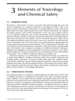
Contemporary industrial plants are inherently com-
plex, large-scale systems requiring complex, mutually
con¯icting automation objectives to be simultaneously
met. Effective control of such systems can only be
made feasible using adequately organized, complex,
large-scale automation systems like the distributed
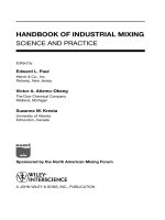
computercontrolsystems[2](Fig.1).Thishasfora
long time been recognized in steel production plants,
where 10 million tons per annum are produced, based
on the operation of numerous work zones and the
associated subsystems like:
Iron zone with coke oven, palletizing and sintering
plant, and blast furnace
Steel zone with basic oxygen and electric arc fur-
nace, direct reduction, and continuous casting
plant, etc.
Mill zone with hot and cold strip mills, plate bore,
and wire and wire rod mill.
To this, the laboratory services and the plant care con-
trol level should be added, where all the required cal-
culations and administrative data processing are
carried out, statistical reviews prepared, and market
prognostics data generated. Typical laboratory services
are the:
Test ®eld
Quality control
Analysis laboratory
Energy management center
Maintenance and repair department
Control and computer center
and typical utilities:
Gas and liquid fuel distribution
Oxygen generation and distribution
Chilled water and compressed air distribution
Water treatment
Steam boiler and steam distribution
Power generation and dispatch.
The dif®culty of control and management of complex
plants is further complicated by permanent necessity of
185
Copyright © 2000 Marcel Dekker, Inc.
steady adaptation to the changing demands, particu-
larly due to the quality variations in the raw materials
and the fact that, although the individual subsystems
are speci®c batch-processing plants, they are ®rmly
incorporated into the downstream and upstream pro-
cesses of the main plant. This implies that the inte-
grated plant automation system has to control,
coordinate, and schedule the total plant production
process.
On the other hand, the complexity of the hierarch-
ical structure of the plant automation is further
expanding because the majority of individual subplants
involved are themselves hierarchically organized, like
the ore yard, coke oven, sintering plant, BOF/LD
(Basic Oxygen Furnace LD-Converter) converter, elec-
tric arc furnace, continuous casting, etc.
Onshore and offshore oil and gas ®elds represent
another typical example of distributed, hierarchically
organized plants requiring similar automation con-
cepts. For instance, a typical onshore oil and gas pro-
duction plant consists of a number of oil and gas
gathering and separation centers, serving a number
of remote degassing stations, where the crude oil and
industrial gas is produced to be distributed via long-
distance pipelines. The gas production includes gas
compression, dehydration, and puri®cation of liquid
components.
The remote degassing stations, usually unmanned
and completely autonomous, have to be equipped
with both multiloop controllers and remote terminal
units that should periodically transfer the data, sta-
tus, and alarm reports to the central computer.
These stations should be able to continue to operate
also when the communication link to the central
computer fails. This is also the case with the gather-
ing and separation centers that have to be equipped
with independent microcomputer-based controllers
[3] that, when the communication link breaks
down, have to automatically start running a prepro-
grammed, failsafe routine. An offshore oil and gas
production installation usually consists of a number
of bridge-linked platforms for drilling and produc-
tion, each platform being able to produce 100,000
or more barrels of crude oil per day and an adequate
quantity of compressed and preprocessed gas.
Attached to the platforms, beside the drilling
modules, are also the water treatment and mud
handling modules, power generation facilities, and
other utilities.
In order to acquire, preprocess, and transfer the
sensing data to the central computer and to obtain
control commands from there, a communication link
is required and at the platform a supervisory control
data acquisition system (SCADA). An additional link
186 Popovic
Figure 1 Distributed computer control system.
Copyright © 2000 Marcel Dekker, Inc.
is requried for interconnection of platforms for
exchange of coordination data.
Finally, a very illustrative example of a distributed,
hierarchically organized system is the power system in
which the power-generating and power-distributing
subsystems are integrated. Here, in the power plant
itself, different subsystems are recognizable, like air,
gas, combustion, water, steam, cooling, turbine, and
generator subsystems. The subsystems are hierarchi-
cally organized and functionally grouped into:
Drive-level subsystem
Subgroup-level subsystem
Group-level subsystem
Unit-level subsystem.
1.2 CLASSICAL APPROACH TO PLANT
AUTOMATION
Industrial plant automation has in the past undergone
three main development phases:
Manual control
Controller-based control
Computer-based control.
The transitions between the individual automation
phases have been so vague that even modern automa-
tion systems still integrate all three types of control.
At the dawn of industrial revolution and for a long
time after, the only kind of automation available was
the mechanization of some operations on the produc-
tion line. Plants were mainly supervised and controlled
manually. Using primitive indicating instruments,
installed in the ®eld, the plant operator was able to
adequately manipulate the likely primitive actuators,
in order to conduct the production process and avoid
critical situations.
The application of real automatic control instru-
mentation was, in fact, not possible until the 1930s
and 40s, with the availability of pneumatic, hydraulic,
and electrical process instrumentation elements such as
sensors for a variety of process variables, actuators,
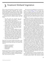
and the basic PID controllers. At this initial stage of
development it was possible to close the control loop
for ¯ow, level, speed, pressure, or temperature control
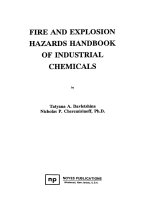
in the ®eld (Fig. 2). In this way, the plants steadily
became more and more equipped with ®eld control
instrumentation, widely distributed through the
plant, able to indicate, record, and/or control indivi-
dual process variables. In such a constellation, the duty
of the plant operator was to monitor periodically the
indicated measured values and to preselect and set the
controlling set-point values.
Yet, the real breakthrough in this role of the plant
operator in industrial automation was achieved in the
1950s by introducing electrical sensors, transducers,
Distributed Control Systems 187
Figure 2 Closed-loop control.
Copyright © 2000 Marcel Dekker, Inc.
actuators, and, above all, by placing the plant instru-
mentation in the central control room of the plant. In
this way, the possibility was given to supervise and
control the plant from one single location using some
monitoring and command facilities. In fact, the intro-
duction of automatic controllers has mainly shifted the
responsibility of the plant operator from manipulating
the actuating values to the adjustment of controllers'
set-point values. In this way the operator became a
supervisory controller.
In the ®eld of plant instrumentation, the particular
evolutionary periods have been marked by the respec-
tive state-of-the art of the available instrumentation
technology, so that here an instrumentation period is
identi®able that is:
Pneumatic and hydraulic
Electrical and electronic
Computer based.
The period of pneumatic and hydraulic plant instru-
mentation was, no doubt, technologically rather primi-
tive because the instrumentation elements used were of
low computational precision. They, nevertheless, have
still been highly reliable andÐabove allÐexplosion
proof, so that they are presently still in use, at least
in the appropriate control zones of the plant.
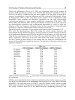
Essential progress in industrial plant control has
been made by introducing electrical and electronic
instrumentation, which has enabled the implementa-
tion of advanced control algorithms (besides PID,
also cascaded, ratio, nonlinear, etc. control), and con-
siderably facilitated automatic tuning of control para-
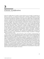
meters. This has been made possible particularly
through the computer-based implementation of indivi-
dual control loops (Fig. 3).
The idea of centralization of plant monitoring and
control facilities was implemented by introducing the
concept of a central control room in the plant, in which
the majority of plant control instrumentation, with the
exception of sensors and actuators, is placed. For con-
necting the ®eld instrumentation elements to the cen-
tral control room pneumatic and electrical data
transmission lines have been installed within the
plant. The operation of the plant from the central con-
trol room is based on indicating, recording, and alarm
elements, situated there, as well asÐfor better local
orientationÐon the use of plant mimic diagrams.
The use of plant mimic diagrams has proven to be so
useful that they are presently still in use.
Microcomputers, usually programmed to solve some
data acquisition and/or control problems in the ®eld,
have been connected, along with other instrumentation
elements, to the facilities of the central control room,
where the plant operators are in charge of centralized
plant monitoring and process control.
Closed-loop control is essential for keeping the
values of process variables, in spite of internal and
external disturbing in¯uences, at prescribed, set-point
values, particularly when the control parameters are
optimally tuned to the process parameters. In indus-
trial practice, the most favored approach for control
parameter tuning is the Ziegler±Nichols method, the
application of which is based on some simpli®ed rela-
tions and some recommended tables as a guide for
determination of the optimal step transition of the
loop while keeping its stability margin within some
given limits. The method is basically applicable to the
stationary, time-invariant processes for which the
values of relevant process parameters are known; the
control parameters of the loop can be tuned of¯ine.
This cannot always hold, so the control parameters
have to be optimally tuned using a kind of trial-and-
error approach, called the Ziegler±Nichols test. It is an
open-loop test through which the pure delay of the
188 Popovic
Figure 3 Computer-based control loop.
Copyright © 2000 Marcel Dekker, Inc.
loop and its ``reaction rate'' can be determined, based
on which the optimal controller tuning can be under-
taken.
1.3 COMPUTER-BASED PLANT
AUTOMATION CONCEPTS
Industrial automation has generally been understood
as an engineering approach to the control of systems
such as power, chemical, petrochemical, cement, steel,
water and wastewater treatment, and manufacturing
plants [4,5].
The initial automation objectives were relatively
simple, reduced to automatic control of a few process
variables or a few plant parameters. Over the years,
there has been an increasing trend toward simulta-
neous control of more and more (or of all) process
variables in larger and more complex industrial plants.
In addition, the automation technology has had to
provide a better view of the plant and process state,
required for better monitoring and operation of the
plant, and for improvement of plant performance
and product quality. The close cooperation between
the plant designer and the control engineer has,
again, directly contributed to the development of bet-
ter instrumentation, and opened perspectives to imple-
ment larger and more complex production units and to
run them at full capacity, by guaranteeing high pro-
duct quality. Moreover, the automation technology is
presently used as a valuable tool for solving crucial
enterprise problems, and interrelating simultaneous
solution of process and production control problems
along with the accompanying ®nancial and organiza-
tional problems.
Generally speaking, the principal objectives of plant
automation are to monitor information ¯ow and to
manipulate the material and energy ¯ow within the
plant in the sense of optimal balance between the pro-
duct quality and the economic factors. This means
meeting a number of contradictory requirements such
as [3]:
Maximal use of production capacity at highest pos-
sible production speed in order to achieve max-
imal production yield of the plant
Maximal reduction of production costs by
Energy and raw material saving
Saving of labor costs by reducing the required
staff and staff quali®cation
Reduction of required storage and inventory
space and of transport facilities
Using low-price raw materials while achieving
the same product quality
Maximal improvement of product quality to meet
the highest international standards while keeping
the quality constant over the production time
Maximal increase of reliability, availability, and
safety of plant operation by extensive plant mon-
itoring, back-up measures, and explosion-proof-
ing provisions
Exact meeting of governmental regulations concern-
ing environmental pollution, the ignorance of
which incurs ®nancial penalties and might pro-
voke social protest
Market-oriented production and customer-oriented
production planning and scheduling in the sense
of just-in-time production and the shortest
response to customer inquiries.
Severe international competition in the marketplace
and steadily rising labor, energy, and raw material
costs force enterprise management to introduce
advanced plant automation, that simultaneously
includes the of®ce automation, required for compu-
ter-aided market monitoring, customer services, pro-
duction supervision and delivery terms checking,
accelerated order processing, extensive ®nancial balan-
cing, etc. This is known as integrated enterprise auto-
mation and represents the highest automation level [1].
The use of dedicated comptuers to solve locally
restricted automation problems was the initial compu-
ter-based approach to plant automation, introduced in
the late 1950s and largely used in the 1960s. At that
time the computer was viewedÐmainly due to its low
reliability and relatively high costsÐnot so much as a
control instrument but rather as a powerful tool to
solve some special, clearly de®ned problems of data
acquisition and data processing, process monitoring,
production recording, material and energy balancing,
production reporting, alarm supervision, etc. This ver-
satile capability of computers has also opened the pos-
sibility of their application to laboratory and test ®eld
automation.
As a rule, dedicated computers have individually
been applied to partial plant automation, i.e., for auto-
mation of particular operational units or subsystems of
the plant. Later on, one single large mainframe com-
puter was placed in the central control room for cen-
tralized, computer-based plant automation. Using
such computers, the majority of indicating, recording,
and alarm-indicating elements, including the plant
mimic diagrams, have been replaced by corresponding
application software.
Distributed Control Systems 189
Copyright © 2000 Marcel Dekker, Inc.
The advent of larger, faster, more reliable, and less
expensive process control computers in the mid 1960s
even encouraged vendors to place the majority of plant
and production automation functions into the single
central computer; this was possible due to the enor-
mous progress in computer hardware and software,
process and man±machine interface, etc.
However, in order to increase the reliability of the
central computer system, some backup provisions have
been necessary, such as backup controllers and logic
circuits for automatic switching from the computer to
the backup controller mode (Fig. 4) so that in the case
of computer failure the controllers take over the last
set-point values available in the computer and freeze
them in the latches available for this purpose. The
values can later on be manipulated by the plant opera-
tor in a similar way to conventional process control.
In addition, computer producers have been working
on some more reliable computer system structures,
usually in form of twin and triple computer systems.
In this way, the required availability of a central con-
trol computer system of at least 99.95% of production
time per year has enormously been increased. To this
comes that the troubleshooting and repair time has
dramatically been reduced through online diagnostic
software, preventive maintenance, and twin-computer
modularity of computer hardware, so that the number
of really needed backup controllers has been reduced
down to a small number of most critical ones.
The situation has suddenly been changed after the
microcomputers have increasingly been exploited to
solve the control problems. The 8-bit microcomputers,
such as Intel's 8080 and Motorola's MC 6800,
designed for bytewise data processing, have proved
to be appropriate candidates for implementation of
programmable controllers [6]. Moreover, the 16- and
32-bit microcomputer generation, to which Intel's
8088 and 8086, Motorola's 68000, Zilog's Z 8000 and
many others belong, has even gained a relatively high
respect within the automation community. They have
worldwide been seen as an ef®cient instrumentation
tool, extremely suitable to solve a variety of automa-
tion problems in a rather simple way. Their high relia-
bility has placed them at the core of digital, single-loop
and multiloop controllers, and has ®nally introduced
the future trend in building automation systems by
transferring more and more programmed control
loops from the central computer into microcomputers,
distributed in the ®eld. Consequently, the duties left to
the central computer have been less and less in the area
of process control, but rather in the areas of higher-
level functions of plant automation such as plant mon-
190 Popovic
Figure 4 Backup controller mode.
Copyright © 2000 Marcel Dekker, Inc.
itoring and supervision. This was the ®rst step towards
splitting up the functional architecture of a computer-
based automation system into at least two hierarchical
levels (Fig. 5):
Direct digital control
Plant monitoring and supervision.
The strong tendency to see the process and produc-
tion control as a unit, typical in the 1970s, soon accel-
erated further architecture extension of computer-
based automation systems by introducing an addi-
tional level on top of the process supervisory level:
the production scheduling and control level. Later on,
the need was identi®ed for building the centralized data
®les of the enterprise, to better exploit the available
production and storage resources within the produc-
tion plant. Finally, it has been identi®ed that direct
access to the production and inventory ®les helps opti-
mal production planning, customer order dispatching,
and inventory control.
In order to integrate all these strongly interrelated
requirements into one computer system, computer
users and producers have come to the agreement that
the structure of a computer system for integrated plant
and production automation should be hierarchical,
comprising at least the following hierarchical levels:
Process control
Plant supervision and control
Production planning and plant management.
This structure has also been professionally implemen-
ted by computer producers, who have launched an
abundant spectrum of distributed computers control
systems, e.g.:
ASEA MASTER (ASEA)
CENTUM (Yokogawa)
CONTRONIC P (Harman and Braun)
DCI 4000 (Fisher and Porter)
HIACS 3000 (Hitachi)
LOGISTAT CP 80 (AEG-Telefunken)
MOD 300 (Taylor Instruments)
PLS (Eckardt)
PMS (Ferranti)
PROCONTROL I (BBC)
PROVOX (Fisher Controls)
SPECTRUM (Foxboro)
TDC 3000 (Honeywell)
TeLEPERM M (Siemens)
TOSDIC (Toshiba).
1.4 AUTOMATION TECHNOLOGY
Development of distributed computer control systems
evidently depends on the development of their essential
parts: hardware, software, and communication links.
Thus, to better conceive the real capabilities of modern
automation systems it is necessary to review the tech-
nological level and the potential application possibili-
ties of the individual parts as constituent subsystems.
Distributed Control Systems 191
Figure 5 Hierarchical systems level diagram.
Copyright © 2000 Marcel Dekker, Inc.
1.4.1 Computer Technology
For more than 10 years, the internal, bus-oriented Intel
80 Â 86 and Motorola 680 Â 0 microcomputer archi-
tectures have been the driving agents for development
of a series of powerful microprocessors. However, the
real computational power of processors came along
with the innovative design of RISC (reduced instruc-
tion set computers) processors. Consequently, the
RISC-based microcomputer concept has soon outper-
formed the mainstream architecture. Today, most fre-
quently used RISC processors are the SPARC (Sun),
Alpha (DEC), R4X00 (MIPS), and PA-RISC (Hewlett
Packard).
Nevertheless, although being powerful, the RISC
processor chips have not found a ®rm domicile within
the mainstream PCs, but rather have become the core
part of workstations and of similar computational
facilities. Their relatively high price has decreased
their market share, compared to microprocessor
chips. Yet, the situation has recently been improved
by introducing emulation possibilities that enable com-
patibility among different processors, so that RISC-
based software can also run on conventional PCs. In
addition, new microprocessor chips with the RISC
architecture for new PCs, such as Power PC 601 and
the like, also promote the use of RISCs in automation
systems. Besides, the appearance of portable operating
systems and the rapid growth the workstation market
contributes to the steady decrease of price-to-perfor-
mance ratio and thus to the acceptance of RISC pro-
cessors for real-time computational systems.
For process control applications, of considerable
importance was the Intel initiative to repeatedly mod-
ify its 80 Â86 architecture, which underwent an evolu-
tion in ®ve successive phases, represented through the
8086 (a 5 MIPS, 29,000-transistor processor), 80286 (a
2 MIPS, 134,000-transistor processor), 80386 (an 8
MIPS, 175,000-transistor processor), 80486 (a 37
MIPS 1.2-million-transistor processor), up to the
Pentium (a 112 and more MIPs, 3.1-million-transistor
processor). Currently, even an over 300 MIPS version
of the Pentium is commercially available.
Breaking the 100 MIPS barrier, up to then mono-
polized by the RISC processors, the Pentium has
secured a threat-free future in the widest ®eld of appli-
cations, relying on existing systems software, such as
Unix, DOS, Windows, etc. This is a considerably lower
requirement than writing new software to ®t the RISC
architecture. Besides, the availability of very advanced
system software, such as operating systems like
Windows NT, and of real-time and object-oriented
languages, has essentially enlarged the application pos-
sibilities of PCs in direct process control, for which
there is a wide choice of various software tools, kits,
and tool boxes, powerfully supporting the computer-
aided control systems design on the PCs. Real-time
application programs developed in this way can also
run on the same PCs, so that the PCs have ®nally
become a constitutional part of modern distributed
computer systems [7].
For distributed, hierarchically organized plant auto-
mation systems, of vital importance are the computer-
based process-monitoring stations, the human±
machine interfaces representing human windows into
the process plant. The interfaces, mainly implemented
as CRT-based color monitors with some connected
keyboard, joystick, mouse, lightpen, and the like, are
associated with individual plant automation levels to
function as:
Plant operator interfaces, required for plant moni-
toring, alarm handling, failure diagnostics, and
control interventions.
Production dispatch and production-monitoring inter-
faces, required for plant production management
Central monitoring interfaces, required for sales,
administrative, and ®nancial management of the
enterprise.
Computer-based human±machine interfaces have
functionally improved the features of the conventional
plant monitoring and command facilities installed in
the central control room of the plant, and completely
replaced them there. The underlying philosophy of new
plant-monitoring interfaces (that only those plant
instrumentation details and only the process variables
selected by the operator are presented on the screen)
releases the operator from the visual saturation present
in the conventional plant-monitoring rooms where a
great number of indicating instruments, recorders,
and mimic diagrams is permanently present and has
to be continuously monitored. In this way the plant
operator can concentrate on monitoring only those
process variables requiring immediate intervention.
There is still another essential aspect of process
monitoring and control that justi®es abandoning the
conventional concept of a central control room, where
the indicating and recording elements are arranged
according to the location of the corresponding sensors
and/or control loops in the plant. This hampers the
operator in a multialarm case in intervening accord-
ingly because in this case the plant operator has to
simultaneously monitor and operationally interrelate
the alarmed, indicated, and required command values
192 Popovic
Copyright © 2000 Marcel Dekker, Inc.
situated at a relative large mutual distance. Using the
screen-oriented displays the plant operator can, upon
request, simultaneously display a large number of pro-
cess and control variables in any constellation. This
kind of presentation can evenÐguided by the situation
in the ®eldÐbe automatically triggered by the
computer.
It should be emphasized that the concept of modern
human interfaces has been shaped, in cooperation
between the vendor designers and the users, for
years. During this time, the interfaces have evolved
into ¯exible, versatile, intelligent, user-friendly work-
places, widely accepted in all industrial sectors
throughout the world. The interfaces provide the user
with a wide spectrum of bene®cial features, such as:
Transparent and easily understandable display of
alarm messages in chronological sequence that
blink, ¯ash, and/or change color to indicate the
current alarm status
Display scrolling by advent of new alarm messages,
while handling the previous ones
Mimic diagram displays showing different details of
different parts of the plant by paging, rolling,
zooming, etc.
Plant control using mimic diagrams
Short-time and long-time trend displays
Real-time and historical trend reports
Vertical multicolor bars, representing values of pro-
cess and control variables, alarm limit values,
operating restriction values, etc.
Menu-oriented operator guidance with multipur-
pose help and support tools.
1.4.2 Control Technology
The ®rst computer control application was implemen-
ted as direct digital control (DDC) in which the com-
puter was used as a multiloop controller to
simultaneously implement tens and hundreds of con-
trol loops. In such a computer system conventional
PID controllers have been replaced by respective PID
control algorithms implemented in programmed digital
form in the following way.
The controller output yt, based on the difference
et between the control input ut and the set-point
value SPV is de®ned as
ytK
p
et
1
T
R
t
0
ed T
D
det
dt
P
R
Q
S
where K
p
is the proportional gain, T
R
the reset time,
and T
D
the rate time of the controller.
In the computer, the digital PID control algorithm
is based on some discrete values of measured process
variables at some equidistant time instants t
0
; t
1
; FFF; t
n
of sampling, so that one has mathematically to deal
with the differences and the sums instead of with deri-
vatives and integrals. Therefore, the discrete version of
the above algorithm has to be developed by ®rst differ-
entiating the above equation, getting
ytK
p
et
1
T
R
etT
D
et
!
where
et and
et are the ®rst and the second deriva-
tive of et, and
yt the ®rst derivative of yt. The
derivatives can be approximated at each sampling
point by
ykykÀyk À 1=Át
ekekÀek À 1=Át
and
ek
ekÀ
ek À 1=Át
to result in
ykÀuk À 1=Át K
p
4
ekÀek À 1
Át
1
T
R
ek
T
D
ekÀ2ek À 1ek À 2
Át
2
5
or in
ykyk À 1K
p
1
Át
T
R
T
D
Át
ek
K
p
À1 À 2T
D
=Átek À 1
K
p
T
D
Át
ek À 2
This is known as the positional PDI algorithm that
delivers the new output value yk, based on its pre-
vious value yk À1 and on some additional calcula-
tions in which the values of et at three successive
samplings are involved. The corresponding velocity
version is
ÁykykÀyk À 1
Better resutls can be achieved using the ``smoothed''
derivative
ek
1
n
nÀ1
i0
e
kÀi
À e
kÀiÀ1
Át
or the ``weighted'' derivative
Distributed Control Systems 193
Copyright © 2000 Marcel Dekker, Inc.
ek
nÀ1
i0
W
i
ek À iÀek À i À 1
Át
nÀ1
i0
W
i
in which the weighting factors are selected, so that
W
i
i
W
0
and
nÀ1
i0
W
i
1
In this case the ®nal digital form of the PID algorithm
is given by
yk yk À 1b
0
ekb
1
ek À 1b
2
ek À 2
b
3
ek À 3b
4
ek À 4
with
b
0
K
p
1
6
Át
T
R
T
D
6Át
b
1
K
p
1
2
T
D
3Át
b
2
K
p
À
1
2
À
T
D
Át
b
3
K
p
À
1
2
T
D
3Át
b
4
K
p
T
D
6Át
Another form of discrete PID algorithm, used in the
®rst DDC implementations, was
ykK
p
ek
1
T
R
k
i0
eiÁt T
D
ekÀek À 1
Át
45
Due to the sampling, the exact values of measured
process variables are known only at sampling
instances. Information about the signal values between
the sampling instances is lost. In addition, the require-
ment to hold the sampled value between two sampling
instants constantly delays the value by half of the sam-
pling period, so that the choice of a large sampling
period is equivalent to the introduction of a relatively
long delay into the process dynamics. Consequently,
the control loop will respond very slowly to the
changes in that set-point value, which makes it dif®cult
to properly manage urgent situations.
The best sampling time Át to be selected for a given
control loop depends on the control algorithm applied
and on the process dynamics. Moreover, the shorter
the sampling time, the better the approximation of
the continuous closed-loop system by its digital equiva-
lent, although this does not generally hold. For
instance, the choice of sampling time has a direct in¯u-
ence on pole displacement of the original (continuous)
system, whose discrete version can in this way become
unstable, unobservable, or uncontrollable.
For systems having only real poles and which are
controlled by a sampled-version algorithm, it is recom-
mended to choose the sampling time between 1/6 and
1/3 of the smallest time constant of the system. Some
practical recommendations plead for sampling times of
1 to 1.5 sec for liquid ¯ow control, 3 to 5 sec of pres-
sure control, and 20 sec for temperature control.
Input signal quantization, which is due to the limited
accuracy of the analog-to-digital converters, is an essen-
tial factor in¯uencing the quality of a digital control
loop. The quantization level can here produce a limit
cycle within the frame of the quantization error made.
The use of analog-to-digital converters with a reso-
lution higher than the accuracy of measuring instru-
ments makes this in¯uence component less relevant.
The same holds for the quantization of the output
signal, where the resolution of the digital-to-analog
converter is far higher than the resolution of position-
ing elements (actuators) used. In addition, due to the
low-pass behavior of the system to be controlled, the
quantization errors of output values of the controller
have no remarkable in¯uence on the control quality.
Also, the problem of in¯uence of the measurement
noise on the accuracy of a digital controllers can be
solved by analog or digital pre®ltering of signals,
before introducing it into the control algorithm.
Although the majority of distributed control sys-
tems is achieving a higher level of sophistication by
placing more emphasis on the strategy in the control
loops, some major vendors of such systems are already
using arti®cial intelligence technology [8] to implement
knowledge-based controllers [9], able to learn online
from control actions and their effects [10,11]. Here,
particularly the rule-based expert controllers and
fuzzy-logic-based controllers have been successfully
used in various industrial branches. The controllers
enable using the knowledge base around the PID algo-
rithm to make the control loop perform better and to
cope with process and system irregularities including
the system faults [12]. For example, Foxboro has
developed the self-tuning controller EXACT based
on a pattern recognition approach [4]. The controller
uses a direct performance feedback by monitoring the
controlled process variable to determine the action
194 Popovic
Copyright © 2000 Marcel Dekker, Inc.
required. It is rule-based expert controller, the rules of
which allow a faster startup of the plant, and adapt the
controller's parameters to the dynamic deviations of
plant's parameters, changing set-point values, varia-
tions of output load, etc.
Allen±Bradley's programmable controller con®g-
uration system (PCCS) provides expert solutions to
the programmable controller application problems in
some speci®c plant installations. Also introduced by
the same vendor is a programmable vision system
(PVS) that performs factory line recognition
inspection.
Accol II, of Bristol Babcock, the language of its
distributed process controller (DPC), is a tool for
building of rule-based control systems. A DPC can
be programmed, using heuristic knowledge, to behave
in the same way as a human plant operator or a con-
trol engineer in the ®eld. The incorporated inference
engine can be viewed as a logical progression in the
enhancement of an advanced, high-level process con-
trol language.
PICON, of LMI, is a real-time expert system for
process control, designed to assist plant operators in
dealing with multiple alarms. The system can manage
up to 20,000 sensing and alarm points and can store
and treat thousands of inference rules for control and
diagnostic purposes. The knowledge acquisition inter-
face of the system allows building of relatively complex
rules and procedures without requiring arti®cial intel-
ligence programming expertise. In cooperation with
LMI, several vendors of distributed computer systems
have incorporated PICON into their systems, such as
Honeywell, Foxboro, Leeds & Northrup, Taylor
Instruments, ASEA±Brown Bovery, etc. For instance,
Leeds & Northrup has incorporated PICON into a
distributed computer system for control of a pulp
and paper mill.
Fuzzy logic controllers [13] are in fact simpli®ed
versions of real-time expert controllers, mainly
based on a collection of IF-THEN rules and on
some declarative fuzzy values of input, output, and
control variables (classi®ed as LOW, VERY LOW,
SMALL, VERY SMALL, HIGH, VERY HIGH,
etc.) are able to deal with the uncertainties and to
use fuzzy reasoning in solving engineering control pro-
blems [14,15]. Thus, they can easily replace any man-
ual operator's control action by compiling the
decision rules and by heuristic reasoning on compiled
database in the ®eld.
Originally, fuzzy controllers were predominantly
used as stand-alone, single-loop controllers, particu-
larly appropriate for solving control problems in the
situations where the dynamic process behavior and
the character of external disturbances is now
known, or where the mathematical process model is
rather complex. With the progress of time, the fuzzy
control software (the fuzzy®er, rule base, rule inter-
preter, and the defuzzi®er) has been incorporated
into the library of control functions, enabling online
con®guration of fuzzy control loops within a distrib-
uted control system.
In the 1990s, efforts have been concentrated on the
use of neurosoftware to solve the process control pro-
blems in the plant by learning from ®eld data [16].
Initially, neural networks have been used to solve cog-
nition problems, such as feature extraction and pattern
recognition. Later on, neurosoftware-based control
schemes have been implemented. Networks have even
been seen as an alternative technology for solving more
complex cognition and control problems based on
their massive parallelism and the connectionist learn-
ing capability. Although the neurocontrollers have
mainly been applied as dedicated controllers in proces-
sing plants, manufacturing, and robotics [17], it is
nevertheless to be expected that with the advent of
low-price neural network hardware the controllers
can in many complex situations replace the current
programmable controllers. This will introduce the pos-
sibility to easily implement intelligent control schemes
[18], such as:
Supervised controllers, in which the neural network
learns the sensor inputs mapping to correspond-
ing actions by learning a set of training examples,
possibly positive and negative
Direct inverse controllers, in which the network
learns the inverse system dynamics, enabling the
system to follow a planned trajectory, particu-
larly in robot control
Neural adaptive control, in which the network learns
the model-reference adaptive behavior on exam-
ples
Back-propagation of utility, in which the network
adapts an adaptive controller based on the results
of related optimality calculations
Adapative critical methods, in which the experiment
is implemented to simulate the human brain cap-
abilities.
Very recently also hybrid, neurofuzzy approaches
have been proposed, that have proven to be very ef®-
cient in the area of state estimation, real-time target
tracking, and vehicle and robot control.
Distributed Control Systems 195
Copyright © 2000 Marcel Dekker, Inc.
1.5 SYSTEMS ARCHITECTURE
In what follows, the overall structure of multicomputer
systems for plant automation will be described, along
with their internal structural details, including data ®le
organization.
1.5.1 Hierarchical Distributed System Structure
The accelerated development of automation technol-
ogy over many decades is a direct consequence of out-
standing industrial progress, innumerable technical
innovations, and a steadily increasing demand for
high-quality products in the marketplace. Process
and production industry, in order to meet the market
requirements, was directly dependent on methods and
tools of plant automation.
On the other hand, the need for higher and higher
automation technology has given a decisive impetus
and a true motivation to instrumentation, control,
computer, and communication engineers to continu-
ally improve methods and tools that help solve the
contemporary ®eld problems. A variety of new meth-
ods has been proposed, classi®ed into new disciplines,
such as signal and system analysis, signal processing,
state-space approach of system theory, model building,
systems identi®cation and parameter estimation, sys-
tems simulation, optimal and adaptive control, intelli-
gent, fuzzy, and neurocontrol, etc. In addition, a large
arsenal of hardware and software tools has been devel-
oped comprising mainframe and microcomputers, per-
sonal computers and workstations, parallel and
massively parallel computers (neural networks), intel-
ligent instrumentation, modular and object-oriented
software experts, fuzzy and neurosoftware, and the
like. All this has contributed to the development of
modern automation systems, usually distributed, hier-
archically organized multicomputer systems, in which
the most advanced hardware, software, and communi-
cation links are operationally integrated.
Modern automation systems require distributed
structure because of the distributed nature of industrial
plants in which the control instrumentation is widely
spread throughout the plant. Collection and preproces-
sing of sensors data requires distributed intelligence
and an appropriate ®eld communication system [19].
On the other hand, the variety of plant automation
functions to be executed and of decisions to be made
at different automation levels require a system archi-
tecture thatÐdue to the hierarchical nature of the
functions involvedÐhas also to be hierarchical.
In the meantime, a layered, multilevel architecture
of plant automation systems has widely been accepted
by the international automation community that
mainlyincludes(Fig.6):
Direct process control level, with process data collec-
tion and preprocessing, plant monitoring and
data logging, open-loop and closed-loop control
of process variables
Plant supervisory control level, at which the plant
performance monitoring, and optimal, adaptive,
and coordinated control is placed
Production scheduling and control level, production
dispatching, supervision, rescheduling and
reporting for inventory control, etc.
Plant management level, that tops all the activities
within the enterprise, such as market and custo-
mer demand analysis, sales statistics, order dis-
patching, monitoring and processing, production
planning and supervision, etc.
Although the manufacturers of distributed compu-
ter control systems design their systems for a wide
application, they still cannot provide the user with all
facilities and all functions required at all hierarchical
levels. As a rule, the user is required to plan the dis-
tribution system to be ordered. In order for the plan-
ning process to be successful, the user has above all to
clearly formulate the premises under with the system
has to be built and the requirements-oriented functions
to be implemented. This should be taken as a selection
guide for system elements to be integrated into the
future plant automation system, so that the planned
system [20]:
Covers all functions of direct control of all process
variables, monitors their values, and enables the
plant engineers optimal interaction with the plant
via sophisticated man±machine interfaces
Offers a transport view into the plant performance
and the state-of-the-art of the production sche-
dule
Provides the plant management with the extensive
up-to-date reports including the statistical and
historical reviews of production and business
data
Improves plant performance by minimizing the
learning cycle and startup and setup trials
Permits faster adaptation to the market demand
tides
Implements the basic objectives of plant automa-
tionÐproduction and quality increase, cost
196 Popovic
Copyright © 2000 Marcel Dekker, Inc.
decrease, productivity and work conditions
improvement, etc.
Based on the above premises, the distributed computer
control system to be selected should include:
A rich library of special software packages for each
control, supervisory, production and manage-
ment level, particularly
At control level: a full set of preprocessing, con-
trol, alarm, and calculation algorithms for
measured process variables that is applicable
to a wide repertoire of sensing and actuating
elements, as well as a versatile display concept
with a large number of operator friendly facil-
ities and screen mimics
At supervisory level: wide alarm survey and tra-
cing possibilities, instantaneous, trend, and
short historical reporting features that include
the process and plant ®les management, along
with special software packages and block-
oriented languages for continuous and batch
process control and for con®guration of plant
mimic diagrams, model building and para-
meter estimation options, etc.
At production level: ef®cient software for online
production scheduling and rescheduling, for
performance monitoring and quality control,
for recipe handling, and for transparent and
exhaustive production data collection and
structured reporting
At management level: abundant stock of profes-
sional software for production planning and
supervision, order dispatch and terms check,
order and sales surveys and ®nancial balancing,
market analysis and customer statistics, etc.
A variety of hardware features
At control level: attachment possibility for most
types of sensors, transducers, and actuators,
reliable and explosion-proof installation,
hard-duty and failsafe version of control
units, online system recon®guration with a
high degree of systems expandability, guaran-
teed further development of control hardware
in the future by the same vendor, extensive
provision of online diagnostic and preventive
maintenance features
At supervisory and production level: wide program
of interactive monitoring options designed to
Distributed Control Systems 197
Figure 6 Bus-oriented hierarchical system.
Copyright © 2000 Marcel Dekker, Inc.
meet the required industrial standards, mult-
iple computer interfaces to integrate different
kinds of servers and workstations using inter-
nationally standardized bus systems and local
area networks, interfacing possibilities for var-
ious external data storage media
At management level: wide integration possibili-
ties of local and remote terminals and work-
stations.
It is extremely dif®cult to completely list all items
important for planning a widespread multicomputer
system that is supposed to enable the implementation
of various operational functions and services.
However, the aspects summarized here represent the
majority of essential guiding aids to the system plan-
ner.
1.5.2 Hierarchical Levels
In order to appropriately lay out a distributed compu-
ter control system, the problems it is supposed to solve
have to be speci®ed [21]. This has to be done after a
detailed plant analysis and by knowledge elicitation
from the plant experts and the experts of different
enterprise departments to be integrated into the auto-
mation system [22]. Should the distributed system
cover automation functions of all hierarchical levels,
a detailed analysis of all functions and services should
be carried out, to result in an implementation report,
from which the hardware and software of the system
are to be planned. In the following, a short review of
the most essential functions to be implemented is given
for all hierarchical levels.
At plant instrumentation level [23], the details should
be listed concerning the
Sensors, actuators, and ®eld controllers to be con-
nected to the system, their type, accuracy, group-
ing, etc.
Alarm occurrences and their locations
Backup concept to be used
Digital displays and binary indicators to be installed
in the ®eld
Completed plant mimic diagrams required
Keyboards and local displays, hand pads, etc. avail-
able
Field bus to be selected.
At this lowest hierarchical level of the system the ®eld-
mounted instrumentation and the related interfaces for
data collections and command distribution for open-
and closed-loop control are situated, as well as the
electronic circuits required for adaptation of terminal
process elements (sensors and actuators) to the com-
puter input/output channels, mainly by signal condi-
tioning using:
Voltage-to-current and current-to-voltage conver-
sion
Voltage-to-frequency and frequency-to-voltage con-
version
Input signal preprocessing (®ltering, smoothing,
etc.)
Signal range switching
Input/output channel selection
Galvanic isolation.
In addition, the signal format and/or digital signal
representation has also to be adapted using:
Analog-to-digital and digital-to-analog conversion
Parallel-to-serial and serial-to-parallel conversion
Timing, synchronization, triggering, etc.
The recent development of FIELDBUS, the interna-
tional process data transfer standard, has directly con-
tributed to the standardization of process interface
because the FIELDBUS concept of data transfer is a
universal approach for interfacing the ®nal ®eld con-
trol elements to the programmable controllers and
similar digital control facilities.
The search for the ``best'' FIELDBUS standard
proposal has taken much time and has created a series
of ``good'' bus implementations that are at least de
facto accepted standards in their application areas,
such as Bitbus, CiA, FAIS, FIP, IEC/ISA, Interbus-
S, mISP, ISU-Bus, LON, Merkur, P-net, PROFIBUS,
SERCOS, Signalbus, TTP, etc. Although an interna-
tionally accepted FIELDBUS standard is still not
available, some proposals have widely been accepted
but still not standardized by the ISO or IEC. One of
such proposals is the PROFIBUS (PROcess FIeld
BUS) for which a user group has been established to
work on implementation, improvement, and industrial
application of the bus.
In Japan, the interest of users has been concentrated
on the FAIS (Factory Automation Interconnection
System) Project, which is expected to solve the problem
of a time-critical communication architecture, particu-
larly important for production engineering. The ®nal
objective of the bus standardization work is to support
the commercial process instrumentation with the built-
in ®eld bus interface. However, also here, ®nding a
unique or a few compatible standard proposals is
extremely dif®cult.
198 Popovic
Copyright © 2000 Marcel Dekker, Inc.
The FIELDBUS concept is certainly the best
answer to the increasing cabling complexity at sensor
and actuator level in production engineering and pro-
cessing industries, which was more dif®cult to manage
using the point-to-point links from all sensors and
actuators to the central control room. Using the
FIELDBUS concept, all sensors and actuators are
interfaced to the distributed computer system in a
unique way, as any external communication facility.
The bene®ts resulting from this are multiple, some of
them being:
Enormous decrease of cabling and installation
costs.
Straightforward adaptation to any future sensor
and actuator technology.
Easy con®guration and recon®guration of plant
instrumentation, automatic detection of trans-
mission errors and cable faults, data transmission
protocol.
Facilitated implementation and use of hot backup
by the communication software.
The problem of common-mode rejection, galvanic
isolation, noise, and crosstalk vanishes due to
digitalization of analog values to be transmitted.
Plant instrumentation includes all ®eld instrumenta-
tion elements required for plant monitoring and con-
trol. Using the process interface, plant instrumentation
is adapted to the input±output philosophy of the com-
puter used for plant automation purposes or to its data
collection bus.
Typical plant instrumentation elements are:
Physical transducers for process parameters
On/off drivers for blowers, power supplies, pumps,
etc.
Controllers, counters, pulse generators, ®lters, and
the like
Display facilities.
Distributed computer control systems have provided a
high motivation for extensive development of plant
instrumentation, above all with regard to incorpora-
tion of some intelligent functions into the sensors
and actuators.
Sensors and actuators [24,25] as terminal control
elements are of primary interest to control engineers,
because the advances of sensor and actuator technol-
ogy open new perspectives in further improvement of
plant automation. In the past, the development of spe-
cial sensors has always enabled solving control pro-
blems that have not been solvable earlier. For
example, development of special sensors for online
measurement of moisture and speci®c weight of run-
ning paper sheet has enabled high-precision control of
the paper-making process. Similar progress in the pro-
cessing industry is expected with the development of
new electromagnetic, semiconductor, ®ber-optic,
nuclear, and biological sensors.
The VLSI technology has de®nitely been a driving
agent in developing new sensors, enabling the extre-
mely small microchips to be integrated with the sensors
or the sensors to be embedded into the microchips. In
this way intelligent sensors [26] or smart transmitters
have been created with the data preprocessing and dig-
tal communication functions implemented in the chip.
This helps increase the measurement accuracy of the
sensor and its direct interfacing to the ®eld bus. The
most preferable preprocessing algorithms implemented
within intelligent sensors are:
Calibration and recalibration in the ®eld
Diagnostic and troubleshooting
Reranging and rescaling
Ambient temperature compensation
Linearization
Filtering and smoothing
Analog-to-digital and parallel-to-serial conversion
Interfacing to the ®eld bus.
Increasing the intelligence of the sensors is simply to be
viewed as a shift of some functions, originally imple-
mented in a microcomputer, to the sensor itself. Much
more technical innovation is contained in the emerging
semiconductor and magnetic sensors, biosensors and
chemical sensors, and particularly in ®ber-optic sen-
sors.
Fiber devices have for a long time been one of the
most promising development ®elds of ®ber-optic tech-
nology [27,28]. For instance, the sensors developed in
this ®eld have such advantages as:
High noise immunity
Insensitivity to electromagnetic interfaces
Intrinsic safety (i.e., they are explosion proof)
Galvanic isolation
Light weight and compactness
Ruggedness
Low costs
High information transfer capacity.
Based on the phenomena they operationally rely on,
the optical sensors can be classi®ed into:
Refractive index sensors
Absorption coef®cient sensors
Fluorescence constant sensors.
Distributed Control Systems 199
Copyright © 2000 Marcel Dekker, Inc.
On the other hand, according to the process used for
sensing of physical variables, the sensors could be:
Intrinsic sensors, in which the ®ber itself carries light
to and from a miniaturized optical sensor head,
i.e., the optical ®ber forms here an intrinsic part
of the sensor.
Extrinsic sensors, in which the ®ber is only used as a
transmission.
It should, nevertheless, be pointed out thatÐin spite
of a wealth of optical phenomena appropriate for sen-
sing of process parametersÐthe elaboration of indus-
trial versions of sensors to be installed in the
instrumentation ®eld of the plant will still be a matter
of hard work over the years to come. The initial enor-
mous enthusiasm, induced by the discovery that ®ber-
optic sensing is viable, has overlooked some consider-
able implementation obstacles of sensors to be
designed for use in industrial environments. As a con-
sequence, there are relatively few commercially avail-
able ®ber-optic sensors applicable to the processing
industries.
At the end of the 1960s, the term integrated optics
was coined, a term analogous to integrated circuits.
The new term was supposed to indicate that in the
future LSI chips, photons should replace electrons.
This, of course, was a rather ambitious idea that was
later amended to become optoelectronics, indicating
the physical merger of photonic and electronic circuits,
known as optical integrated circuits. Implementation of
such circuits is based on thin-®lm waveguides, depos-
ited on the surface of a substrate or buried inside it.
At the process control level, details should be given
(Fig. 7) concerning:
Individual control loops to be con®gured, including
their parameters, sampling and calculation time
intervals, reports and surveys to be prepared,
fault and limit values of measured process vari-
ables, etc.
Structured content of individual logs, trend records,
alarm reports, statistical reviews, and the like
Detailed mimic diagrams to be displayed
Actions to be effected by the operator
Type of interfacing to the next higher priority level
exceptional control algorithms to be implemen-
ted.
At this level the functions required for collection and
processing of sensor data, for process control algo-
rithms, as well as the functions required for calculation
of command values to be transferred to the plant are
stored. Examples of such functions are functions for
data acquisition functions include the operations needed
for sensor data collection. They usually appear as
initial blocks in an open- or closed-loop control
chain, and represent a kind of interface between the
system hardware and software. In the earlier process
control computer systems, the functions were known
as input device drivers and were usually a constituent
part of the operating system. To the functions belong:
Analog data collection
Thermocouple data collection
Digital data collection
Binary/alarm data collection
Counter/register data collection
Pulse data collection.
As parameters, usually the input channel number,
ampli®cation factor, compensation voltage, conversion
200 Popovic
Figure 7 Functional hierarchical levels.
Copyright © 2000 Marcel Dekker, Inc.
factors, and others are to be speci®ed. The functions
can be triggered cyclically (i.e., program controlled)or
event-driven (i.e., interrupt controlled).
Input signal-conditioning algorithms are mainly used
for preparation of acquired plant data, so that the data
canÐafter being checked and testedÐbe directly used
in computational algorithms. Because the measured
data have to be extracted from a noisy environment,
the algorithms of this group must include features like
separation of signal from noise, determination of phy-
sical values of measured process variable, decoding of
digital values, etc.
Typical signal-conditioning algorithms are:
Local linearization
Polynomial approximation
Digital ®ltering
Smoothing
Bounce suppression of binary values
Root extraction for ¯ow sensor values
Engineering unit conversion
Encoding, decoding, and code version.
Test and check functions are compulsory for correct
application of control algorithms that always have to
operate on true values of process variables. Any error
in sensing elements, in data transfer lines, or in input
signal circuits delivers a false measured value whichÐ
when applied to a control algorithmÐcan lead to a
false or even to a catastrophic control action. On the
other hand, all critical process variables have to be
continuously monitored, e.g., checked against their
limit values (or alarm values), whose crossing certainly
indicates the emergency status of the plant.
Usually, the test and check algorithms include:
Plausibility test
Sensor/transmitter test
Tolerance range test
Higher/lower limit test
Higher/lower alarm test
Slope/gradient test
Average value test.
As a rule, most of the anomalies detected by the
described functions are, for control and statistical pur-
poses, automatically stored in the system, along with
the instant of time they have occurred.
Dynamic compensation functions are needed for spe-
ci®ed implementation of control algorithms. Typical
functions of this group are:
Lead/lag
Dead time
Differentiate
Integrator
Moving average
First-order digital ®lter
Sample-and-hold
Velocity limiter.
Basic control algorithms mainly include the PID algo-
rithm and its numerous versions, e.g.:
PID-ratio
PID-cascade
PID-gap
PID-auto-bias
PID-error squared
I, P, PI, PD
As parameters, the values like proportional gain, inte-
gral reset, derivative rate, sampling and control inter-
vals, etc. have to be speci®ed.
Output signal condition algorithms adapt the calcu-
lated output values to the ®nal or actuating elements to
be in¯uenced. The adaptation includes:
Calculation of full, incremental, or percentage
values of output signals
Calculation of pulse width, pulse rate, or number of
pulses for outputting
Book-keeping of calculated signals, lower than the
sensitivity of ®nal elements
Monitoring of end values and speed saturation of
mechanical, pneumatic, and hydraulic actuators.
Output functions corresponds, in the reversed sense, to
the input functions and include the analog, digital, and
pulse output (e.g., pulse width, pulse rate, and/or pulse
number).
Atplantsupervisorylevel(Fig.7)thefunctionsare
concentrated, required for optimal process control,
process performance monitoring, plant alarm manage-
ment, and the like. For optimal process control,
advanced, model-based control strategies are used
such as:
Feed-forward control
Predictive control
Deadbeat control
State-feedback control
Adaptive control
Self-tuning control.
When applying the advanced process control, the:
Mathematical process model has to be built.
Distributed Control Systems 201
Copyright © 2000 Marcel Dekker, Inc.
Optimal performance index has to be de®ned, along
with the restriction on process or control vari-
ables.
Set of control variables to be manipulated for the
automation purposes has to be identi®ed.
Optimization method to be used has to be selected.
In engineering practice, the least-squares error is used
as performance index to be minimized, but a number of
alternative indices are also used in order to attain:
Time optimal control
Fuel optimal control
Cost optimal control
Composition optimal control.
Adaptive control [29] is used for implementation of
optimal control that automatically accommodates the
unpredictable environmental changes or signal and
system uncertainties due to the parameter drifts or
minor component failures. In this kind of control,
the dynamic systems behavior is repeatedly traced
and its parameters estimated whichÐin the case of
their deviation from the given optimal valuesÐhave
to be compensated in order to retain their constant
values.
In modern control theory, the term self-tuning con-
trol [30] has been coined as alternative to adaptive
control. In a self-tuning system control parameters
are, based on measurements of system input and out-
put, automatically tuned to result into a sustained opti-
mal control. The tuning itself can be affected by the use
of measurement results to:
Estimate actual values of system parameters and,
in the sequence, to calculate the corresponding
optimal values of control parameters, or to
Directly calculate the optimal values of control
parameters.
Batch process control is basically a sequential, well-
timed stepwise control that in addition to a prepro-
grammed time interval generally includes some binary
state indicators, the status of which is taken at each
control step as a decision support for the next control
step to be made. The functional modules required for
con®guration of batch control software are:
Timers, to be preset to required time intervals or to
the real-time instants
Time delay modules, time- or event-driven, for deli-
miting the control time intervals
Programmable up-count and down-count timers as
time indicators for triggering the preprogrammed
operational steps
Compactors as decision support in initiation of new
control sequences
Relational blocks as internal message elements of
control status
Decision tables, de®ningÐfor speci®ed input condi-
tionsÐthe corresponding output conditions to be
executed.
In a similar way the recipe handling is carried out. It
is also a batch-process control, based on stored recipes
to be downloaded from a mass storage facility contain-
ing the completed recipes library ®le. The handling
process is under the competence of a recipe manager,
a batch-process control program.
Energy management software takes care that all
available kinds of energy (electrical, fuel, steam,
exothermic heat, etc.) are optimally used, and that
the short-term (daily) and long-term energy demands
are predicted. It continuously monitors the generated
and consumed energy, calculates the ef®ciency index,
and prepares the relevant cost reports. In optimal
energy management the strategies and methods are
used, which are familiar in optimal control of station-
ary processes.
Contemporary distributed computer control sys-
tems are equipped with a large quantity of different
software packages classi®ed as:
System software, i.e., the computer-oriented soft-
ware containing a set of tools for development,
generation, test, run, and maintenance of pro-
grams to be developed by the user
Application software, to which the monitoring, con-
trol loop con®guration, and communication soft-
ware belong.
System software is a large aggregation of different
compilers and utility programs, serving as systems
development tools. They are used for implementation
of functions that could not be implemented by any
combination of program modules stored in the library
of functions. When developed and stored in the library,
the application programs extend its content and allow
more complex control loops to be con®gured.
Although it is, at least in principle, possible to develop
new programmed functional modules in any languages
available in process control systems, high-level lan-
guages like:
Real-time languages
Process-oriented languages
are still preferred for such development.
202 Popovic
Copyright © 2000 Marcel Dekker, Inc.
Real-time programming languages are favored as
support tools for implementation of control software
because they provide the programmer with the neces-
sary features for sensor data collection, actuator data
distribution, interrupt handling, and programmed real-
time and difference-time triggering of actions. Real-
time FORTRAN is an example of this kind of high-
level programming language.
Process-oriented programming languages go one step
further. They also support planning, design, genera-
tion, and execution of application programs (i.e., of
their tasks). They are higher-level languages with multi-
tasking capability, that enables the programs, imple-
mented in such languages, to be simultaneously
executed in an interlocked mode, in which a number
of real-time tasks are executed synchronously, both in
time- or event-driven mode. Two outstanding exam-
ples of process-oriented languages are:
Ada, able to support implementation of complex,
comprehensive system automation software in
which, for instance, the individual software
packages, generated by the members of a pro-
gramming team, are integrated in a cooperative,
harmonious way
PEARL (Process and Experiment Automation
Real-Time Language), particularly designed for
laboratory and industrial plant automation,
where the acquisition and real-time processing
of various sensor data are carried out in a multi-
tasking mode.
In both languages, a large number of different kinds of
data can be processed, and a large-scale plant can be
controlled by decomposing the global plant control
problem into a series of small, well-de®ned control
tasks to run concurrently, whereby the start, suspen-
sion, resumption, repetition, and stop of individual
tasks can be preprogrammed, i.e., planned.
In Europe, and particularly in Germany, PEARL is
a widespread automation language. It runs in a num-
ber of distributed control systems, as well as in diverse
mainframes and personal computers like PDP-11,
VAX 11/750, HP 3000, and Intel 80x86, Motorola
68000, and Z 8000.
Besides the general purpose, real-time and process-
oriented languages discussed here, the majority of
commercially available distributed computer control
systems are well equipped with their own, machine-
speci®c, high-level programming languages, specially
designed for facilitation of development of user-tailored
application programs.
Attheplantmanagementlevel(Fig.7)avastquan-
tity of information should be provided, not familiar to
the control engineer, such as information concerning:
Customer order ®les
Market analysis data
Sales promotion strategies
Files of planned orders along with the delivery
terms
Price calculation guidelines
Order dispatching rules
Productivity and turnover control
Financial surveys
Much of this is to be speci®ed in a structured, alpha-
numeric or graphical form, this becauseÐapart from
the data to be collectedÐeach operational function to
be implemented needs some data entries from the lower
neighboring layer, in order to deliver some output data
to the higher neighboring layer, or vice versa. The data
themselves have, for their better management and
easier access, to be well-structured and organized in
data ®les. This holds for data on all hierarchical levels,
so that in the system at least the following databases
are to be built:
Plant databases, containing the parameter values
related to the plant
Instrumentation databases, where the data are stored
related to the individual ®nal control elements
and the equipment placed in the ®eld
Control databases, mainly comprising the con®gura-
tion and parametrization data, along with the
nominal and limit values of the process variable
to be controlled
Supervisory databases required for plant perfor-
mance monitoring and optimal control, for
plant modeling and parameter estimation, as
well as production monitoring data
Production databases for accumulation of data rele-
vant to raw material supplies, energy and pro-
ducts stock, production capacity and actual
product priorities, for speci®cation of product
quality classes, lot sizes and restrictions, stores
and transport facilities, etc.
Management databases, for keeping trace of custo-
mer orders and their current status, and for stor-
ing the data concerning the sales planning, raw
material and energy resources status and
demands, statistical data and archived long-
term surveys, product price calculation factors,
etc.
Distributed Control Systems 203
Copyright © 2000 Marcel Dekker, Inc.
Before the structure and the required volume of the
distributed computer system can be ®nalized, a large
number of plant, production, and management-rele-
vant data should be collected, a large number of
appropriate algorithms and strategies selected, and a
considerable amount of speci®c knowledge by inter-
viewing various experts elucidated through the system
analysis. In addition, a good system design demands a
good cooperation between the user and the computer
system vendor because at this stage of the project plan-
ning the user is not quite familiar with the vendor's
system, and because the vendor shouldÐon the user's
requestÐimplement some particular application pro-
grams, not available in the standard version of system
software.
After ®nishing the system analysis, it is substantial
to entirely document the results achieved. This is par-
ticularly important because the plants to be auto-
mated are relatively complex and the functions to
be implemented distributed across different hierarch-
ical levels. For this purpose, the detailed instrumenta-
tion and installation plans should be worked out
using standardized symbols and labels. This should
be completed with the list of control and display ¯ow
charts required. The programmed functions to be
used for con®guration and parametrization purposes
should be summarized in a tabular or matrix form,
using the ®ll-in-the-blank or ®ll-in-the-form technique,
ladder diagrams, graphical function charts, or in spe-
cial system description languages. This will certainly
help the system designer to better tailor the hardware
and the system programmer to better style the soft-
ware of the future system.
To the central computer system a number of compu-
ters and computer-based terminals are interconnected,
executing speci®c automation functions distributed
within the plant. Among the distributed facilities
only those directly contributing to the plant automa-
tion are important, such as:
Supervisory stations
Field control stations
Supervisory stations are placed at an intermediate level
between the central computer system and the ®eld con-
trol stations. They are designed to operate as autono-
mous elements of the distributed computer control
system executing the following functions:
State observation of process variables
Calculation of optimal set-point values
Performance evaluation of the plant unit they
belong to
Batch process control
Production control
Synchronization and backup of subordinated ®eld
control stations
Because they belong to some speci®c plant units, the
supervisory stations are provided with special applica-
tion software for material tracking, energy balancing,
model-based control, parameter tuning of control loops,
quality control, batch control, recipe handling, etc.
In some applications, the supervisory stations ®gure
as group stations, being in charge of supervision of a
group of controllers, aggregates, etc. In the small-scale
to middle-scale plants also the functions of the central
computer system are allocated to such stations.
A brief review of commercially available systems
shows that the following functions are commonly
implemented in supervisory stations:
Parameter tuning of controllers: CONTRONIC
(ABB), DCI 5000 (Fisher and Porter), Network
90 (Bailey Controls), SPECTRUM (Foxboro),
etc.
Batch control: MOD 300 (Taylor Instruments),
TDC 3000 (Honeywell), TELEPERM M
(Siemens), etc.
Special, high-level control: PLS 80 (Eckhardt),
SPECTRUM, TDC 3000, CONTRONIC P,
NETWORK 90, etc.
Recipe handling: ASEA-Master (ABB), CENTUM
and YEWPACK II (Yokogawa), LOGISTAT
CP-80 (AEG Telefunken), etc.
The supervisory stations are also provided with the
real-time and process-oriented general or speci®c
high-level programming languages like FORTRAN,
RT-PASCAL, BASIC, CORAL [PMS (Ferranti)],
PEARL, PROSEL [P 4000 (Kent)], PL/M, TML, etc.
Using the languages, higher-level application programs
can be developed.
At the lowest hierarchical level the ®eld control sta-
tions, i.e., the programmable controllers are placed,
along with some process monitors. The stations, as
autonomous subsystems, implement up to 64 control
loops. The software available at this control level
includes the modules for
Process data acquisition
Process control
Control loop con®guration
Process data acquisition software, available within the
contemporary distributed computer control systems, is
modular software, comprising the algorithms [31] for
204 Popovic
Copyright © 2000 Marcel Dekker, Inc.
sensors, data collection, and preprocessing, as well as
for actuator data distribution [31,32]. The software
modules implement functions like:
Input device drivers, to serve the programming of
analog, digital, pulse, and alarm or interrupt
inputs, both in event drivers or in cyclic mode
Input signal conditioning, to preprocess the collected
sensor values by applying the linearization, digi-
tal ®ltering and smoothing, bounce separation,
root extraction, engineering conversion, encod-
ing, etc.
Test and check operations, required for signal plau-
sibility and sensor/transmitter test, high and low
value check, trend check, etc.
Output signal conditioning, needed for adapting the
output values to the actuator driving signals, like
calculation of full and incremental output values,
based on the results of the control algorithm
used, or the calculation of pulse rate, pulse
width, or the total number of pulses for output-
ting
Output device drivers, for execution of calculated
and conditioned output values.
Process control software, also organized in modular
form, is a collection of control algorithms, containing:
Basic control algorithms, i.e., the PID algorithm and
its various modi®cations (PID ratio, cascade,
gap, autobias, adaptive, etc.)
Advanced control algorithms like feed-forward, pre-
dictive, deadbeat, state feedback, self-tuning,
nonlinear, and multivariable control.
Control loop con®guration [33] is a two-step proce-
dure, used for determination of:
Structure of individual control loops in terms of
functional modules used and of their interlink-
age, required for implementation of the desired
overall characteristics of the loop under con®g-
uration, thus called the loop's con®guration step
Parameter values of functional modules involved in
the con®guration, thus called the loop's parame-
trization step.
Once con®gured, the control loops are stored for their
further use. In some situations also the parameters of
the block in the loop are stored.
Generally, the functional blocks available within the
®eld control stationsÐin order not to be destroyedÐ
are stored in ROM or EPROM as a sort of ®rmware
module, whereas the data generated in the process of
con®guration and parametrization are stored in RAM,
i.e., in the memory where the con®gured software runs.
It should be pointed out that every block required
for loop con®gurations is stored only once in ROM, to
be used in any numbers of loops con®gured by simply
addressing it, along with the pertaining parameter
values in the block linkage data. The approach actually
represents a kind of soft wiring, stored in RAM.
For multiple use of functional modules in ROM,
their subroutines should be written in re-entrant
form, so that the start, interruption, and continuation
of such a subroutine with different initial data and
parameter values is possible at any time.
It follows that once having all required functional
blocks as a library of subroutine modules, and the tool
for their mutual patching and parameterization, the
user can program the control loops in the ®eld in a
ready-to-run form. The programming is here a rela-
tively easy task because the loop con®guration means
that, to implement the desired control loop, the
required subroutine modules should be taken from
the library of functions and linked together.
1.5.3 Data File Organization
The functions, implemented within the individual func-
tional layers, need some entry data in order to run and
generate some data relevant to the closely related func-
tions at the ``neighboring'' hierarchical levels. This
means that the automation functions implemented
should directly access some relevant initial data to gen-
erate some data of interest to the neighboring hierarch-
ical levels. Consequently, the system functions and the
relevant data should be allocated according to their
tasks; this represents the basic concept of distributed,
hierarchically organized automation systems: automa-
tion functions should be stored where they are needed,
and the data where they are generated, so that only
some selected data have to be transferred to the adja-
cent hierarchical levels. For instance, data required for
direct control and plant supervision should be allo-
cated in the ®eld, i.e., next to the plant instrumentation
and data, required for higher-level purposes, should be
allocated near to the plant operator.
Of course, the organization of data within a hiera-
chically structured system requires some speci®c con-
siderations concerning the generation, access,
updating, protection, and transfer of data between dif-
ferent ®les and different hierarchical levels.
As common in information processing systems, the
data are basically organized in ®les belonging to the
relevant database and being distributed within the sys-
Distributed Control Systems 205
Copyright © 2000 Marcel Dekker, Inc.
tem, so that the problem of data structure, local and
global data relevance, data generation and access, etc.
is the foreground one. In a distributed computer con-
trol system data are organized in the same way as their
automation functions: they are attached to different
hierarchical levels [4]. At each hierarchical level, only
the selected data are received from other levels,
whereby the intensity of the data ¯ow ``upward''
through the system decreases, and in the opposite
direction increases. Also, the communication fre-
quency between the ``lower'' hierarchical levels is
higher, and the response time shorter than between
the ``higher'' hierarchical levels. This is due to the auto-
mation functions of lower levels servicing the real-time
tasks, whereas those of the higher levels service some
long-term planning and scheduling tasks.
The content of individual database units (DB) (Fig.
8) basically depends on their position within the hier-
archical system. So, the process database (Fig. 9), situ-
ated at process control level, contains the data
necessary for data acquisition, preprocessing, check-
ing, monitoring and alarm, open- and closed-loop con-
trol, positioning, reporting, logging, etc. The database
unit also contains, as long-term data, the speci®cations
concerning the loop con®guration and the parameters
of individual functional blocks used. As short-term
data it contains the measured actual values of process
variables, the set-point values, calculated output
values, and the received plant status messages.
Depending on the nature of the implemented func-
tions, the origin of collected data, and the destination
of generated data, the database unit at process control
level hasÐin order to handle a large number of short-
life data having a very fast accessÐto be ef®cient under
real-time conditions. To the next ``higher'' hierarchical
level only some actual process values and plant status
messages are forwarded, along with short history of
some selected process variables. In the reverse direc-
tion, calculated optimal set-point values for controllers
are respectively to be transferred.
The plant database, situated at supervision control
level, contains data concerning the plant status, based
on which the monitoring, supervision, and operation
ofplantiscarriedout(Fig.10).Aslong-termdata,the
database unit contains the speci®cations concerning
the available standard and user-made displays, as
well as data concerning the mathematical model of
the plant. As short-term data the database contains
the actual status and alarm messages, calculated values
of process variables, process parameters, and optimal
set-point values for controllers. At the hierarchical
206 Popovic
Figure 8 Individual DB units.
Figure 9 Process DB.
Copyright © 2000 Marcel Dekker, Inc.
level, a large number of data are stored whose access
time should be within a few seconds. Here, some cal-
culated data have to be stored for a longer time (his-
torical, statistical, and alarm data), so that for this
purpose hard disks are used as backup storage. To
the ``higher'' hierarchical level, only selected data are
transferred for production scheduling, and directives
are received.
The production database, situated at production
schedulingandcontrollevel(Fig.11),containsdata
concerning the products and raw material stocks, pro-
duction schedules, production goals and priorities, lot
sizes and restrictions, quality control as well as the
store and transport facilities. As long-term data the
archived statistical and plant alarm reports are stored
in bulk memories. The data access time is here in no
way critical. To the ``higher'' hierarchical level, the
status of the production and order processing, as well
as of available facilities necessary for production
replanning is sent, and in the reverse direction the tar-
get production data.
Finally, the management database, stored at corpo-
rateorenterprisemanagementlevel(Fig.12),contains
data concerning the customer orders, sales planning,
product stocks and production status, raw material
and energy resources and demands, status of store
and transport facilities, etc. Data stored here are
long-term, requiring access every few minutes up to
many weeks. For this reason, a part of the database
can be stored on portable magnetic media, where it can
be deposited for many years for statistical or adminis-
trative purposes.
The fact that different databases are built at differ-
ent hierarchical levels and possibly stored in different
computers, administrated by different database man-
agement or operating systems, makes the access of any
hierarchical level dif®cult. Inherent problems here are
the problems of formats, log output procedures, con-
currency control, and other logical differences con-
cerning the data structures, data management
languages, label incompatibilities, etc. In the mean-
time, some appraoches have been suggested for solving
some of the problems, but there is still much creative
work to be done in this ®eld in order to implement
¯exible, level-independent access to any database in a
distributed computer system.
Another problem, typical for all time-related data-
bases, such as the real-time and production manage-
ment databases, is the representation of time-related
data. Such data have to be integrated into the context
of time, a capability that the conventional database
management systems do not have. In the meantime,
numerous proposals have been made along this line
which include the time to be stored as a universal attri-
Distributed Control Systems 207
Figure 10 Database of supervisory control level.
Copyright © 2000 Marcel Dekker, Inc.
bute. The attribute itself can, for instance, be transac-
tion time, valid time, or any user-de®ned time.
Recently, four types of time-related databases have
been de®ned according to their ability to support the
time concepts and to process temporal information:
Snapshot databases, i.e., databases that give an
instance or a state of the data stored concern-
ing the system (plant, enterprise) at a certain
instant of time, but not necessarily correspond-
ing to the current status of the system. By
insertion, deletion, replacement, and similar
data manipulation a new snapshot database
can be prepared, re¯ecting a new instance or
state of the system, whereby the old one is
de®nitely lost.
Rollback databases, e.g., a series of snapshot data-
bases, simultaneously stored and indexed by
transaction time, that corresponds to the instant
of time the data have been stored in the database.
The process of selecting a snapshot out of a roll-
back database is called rollback. Also here, by
insertion of new and deletion of old data (e.g.,
of individual snapshots) the rollback databases
can be updated.
Historical databases, in fact snapshot databases in
valid time, i.e., in the time that was valid for the
systems as the databases were built. The content
of historical databases is steadily updated by
deletion of invalid data, and insertion of actual
data acquired. Thus, the databases always re¯ect
the reality of the system they are related to. No
208 Popovic
Figure 11 Database of production scheduling and control level.
Figure 12 Management database.
Copyright © 2000 Marcel Dekker, Inc.
data belonging to the past are kept within the
database.
Temporal databases are a sort of combination of
rollback and historical databases, related both
to the transition time and the valid time.
1.6 COMMUNICATION LINKS REQUIRED
The point-to-point connection of ®eld instrumentation
elements (sensors and actuators) and the facilities
located in the central control room is highly in¯exible
and costly. This total reduction of wiring and cable-
laying expenses remains the most important objective
when installing new, centralized automation systems.
For this purpose, the placement of a remote process
interface in the ®eld multiplexers and remote terminal
units (RTUs) was the initial step in partial system
decentralization. With the availability of microcompu-
ters the remote interface and remote terminal units
have been provided with the due intelligence so that
gradually some data acquisition and preprocessing
functions have been also transferred to the frontiers
of the plant instrumentation.
Yet, data transfer within the computer-based, dis-
tributed hierarchical system needs an ef®cient, univer-
sal communication approach for interconnecting the
numerous intelligent, spatially distributed subsystems
at all automation levels. The problems to be solved in
this way can be summarized as follows:
At ®eld level: interconnection of individual ®nal ele-
ments (sensors and actuators), enabling their tel-
ediagnostics and remote calibration capability
At process control level: implementation of indivi-
dual programmable control loops and provision
of monitoring, alarms, and reporting of data
At production control level: collection of data
required for production planning, scheduling, mon-
itoring, and control
At management level: integration of the production,
sales, and other commercial data required for
order processing and customer services.
In the last two or more decades much work has been
done on standardization of a data communication
links, particularly appropriate for transfer of process
data from the ®eld to the central computer system. In
this context, Working Group 6 of Subcommittee 65C
of the International Electrotechnical Commission
(IEC), the scope of which concern the Digital Data
Communications for Measurement and Control, has
been working on PROWAY (Process Data
Highway), an international standard for a high-
speed, reliable, noise immune, low-cost data transfer
within the plant automation systems. Designed as a
bus system, PROWAY was supposed to guarantee
the data transfer rate of 1 Mbps over a distance of 3
km, with up 100 participants attached along the bus.
However, due to the IEEE work on project 802 on
local area networks, which at the time of standardiza-
tion of PROWAY had already been accepted by the
communication community, the implementation of
PROWAY was soon abandoned.
The activity of the IEEE in the ®eld of local area
networks was welcomed by both the IEC and the
International Organization for Standardization (ISO)
and has been converted into corresponding interna-
tional standards. In addition, the development of mod-
ern intelligent sensors and actuators, provided by
telediagnostics and remote calibration capabilities,
has stimulated the competent professional organiza-
tions (IEC, ISA, and the IEEE itself) to start work
on the standardization of a special communication
link, appropriate for direct transfer of ®eld data, the
FIELDBUS. The bus standard was supposed to meet
at least the following requirements:
Multiple drop and redundant topology, with a total
length of 1.5 km or more.
For data transmission twisted pair, coax cable, and
optical ®ber should be applicable.
Single-master and multiple-master bus arbitration
must be possible in multicast and broadcast
transmission mode.
Access time of 5±20 sec or a scan rate of 100 samples
per second should be guaranteed.
High-reliability with the error detection features
built in the data transfer protocol.
Galvanic and electrical (>250 V) isolation.
Mutual independence of bus participants.
Electromagnetic compatibility.
The requirements have simultaneously been worked
out by IEC TC 65C, ISA SP 50, and IEEE P 1118.
However, no agreement has been achieved on ®nal
standard document because four standard candidates
have been proposed:
BITBUS (Intel)
FIP (Factory Instrumentation Protocol) (AFNOR)
MIL-STD-1533 (ANSI)
PROFIBUS (Process Field Bus) (DIN).
The standardization work in the area of local area net-
works, however, has in the last more than 15 years
Distributed Control Systems 209
Copyright © 2000 Marcel Dekker, Inc.