Introduction to GPS The Global Positioning System - Part 9 pdf
Bạn đang xem bản rút gọn của tài liệu. Xem và tải ngay bản đầy đủ của tài liệu tại đây (846.64 KB, 11 trang )
9
GPS Integration
GPS has found its way into many applications, mainly as a result of its
accuracy, global availability, and cost-effectiveness. Unfortunately, how-
ever, there exist some situations in which part of the GPS signal may be
obstructed to the extent that the GPS receiver may not see enough satel-
lites for positioning. Examples of those situations are positioning in urban
canyons and deep open-pit mining. This signal-obstruction problem,
however, was successfully overcome by integrating GPS with other posi-
tioning systems. In fact, reported results showed that the performance of
the integrated system is better than either system alone. Augmenting GPS
is not limited to sensor integration. As shown below, GPS can be aug-
mented with computer-based tools, such as GIS, for efficient data collec-
tion and analysis.
9.1 GPS/GIS integration
A geographic information system (GIS) is a computer-based tool capable
of acquiring, storing, manipulating, analyzing, and displaying spatially
referenced data [1]. Spatially referenced data is data that is identified
117
according to its geographic location (e.g., features such as streets, light
poles, and fire hydrants are linked by geography).
Spatial, or geographic, data can be obtained from a variety of sources
such as existing maps, satellite imagery, and GPS. Once the information is
collected, a GIS stores it as a collection of layers in the GIS database (see
Figure 9.1). The GIS can then be used to analyze the information and deci-
sions can be made efficiently. (For example, the decision to build a new
road can be made by studying the effect of one feature, such as traffic
volume.)
GPS is used to collect the GIS field data efficiently and accurately [2].
With GPS, the data is collected in a digital format in either real-time or
postprocessed mode. A number of GPS/GIS systems that provide centime-
ter- to meter-level accuracy are now available on the market. Most of these
systems allow the user to enter user-defined attributes for each feature.
Built-in navigation functions to relocate field assets are also available. Pen
computer-based systems are used by some GPS receiver manufacturers to
allow the data to be edited and displayed as it is collected [2].
Many industries, including utilities management, forestry, agriculture,
public safety, and fleet management, can benefit from integrated GPS/GIS
systems.
9.2 GPS/LRF integration
In areas with heavy tree canopy, GPS receivers will normally lose lock to the
GPS satellites. In addition, real-time differential GPS corrections may not
be received as well. To overcome these problems, integrated GPS/handheld
laser units, or laser range finders (LRFs), were developed [3]. The way the
integrated system operates is to set up the GPS antenna in a nearby open
area, which allows the GPS system to operate normally without losing lock
to the GPS satellites. With the help of a digital compass, a reflectorless
handheld laser, colocated with the GPS receiver, can be used to determine
the distance and azimuth to the inaccessible points (see Figure 9.2). This
operation is commonly known as the offset function. Software residing in
the handheld computer helps in collecting both the offset data and the GPS
data. At a later time, all the available information is processed using PC
software to determine the coordinates of the inaccessible points. Collecting
and processing the data may also be done in real time, while in the field,
118 Introduction to GPS
GPS Integration 119
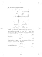
Feature:
Tree§
Attributes:
§
§
§
§
Type
Height
Diameter
Health
Rivers and trees
Contours
FH
Roads
Figure 9.1 GPS/GIS integration.
Figure 9.2 GPS/LRF integration.
provided that the real-time DGPS corrections can be received. Once the
processing is done, the user can export the output to the required GIS or
CAD software. This eliminates the need to place the GPS antenna directly
on the features to be mapped [2].
GPS/laser integration is an attractive tool, especially for the forestry
industry. Tree offsets, heights, and diameters can be measured easily with
the laser unit. From a single location, a stationary user in a relatively open
area can offset any number of points or features. In this case, the user loca-
tion will be determined precisely by averaging all the GPS data collected
while taking the offset measurements. Other applications of the GPS/laser
integration include mapping points under bridges, mapping points on a
busy roadway, mapping highway signs, and mapping shore lines, to name a
few. GPS/laser integration can be used to map point features, line features,
or area features.
9.3 GPS/dead reckoning integration
Another system that has been used to supplement GPS under poor signal
reception is the dead reckoning (DR) system. Dead reckoning is a low-cost
system, commonly comprising an odometer sensor and a vibration gyro-
scope. The integrated GPS/DR system is widely used in automatic vehicle
location (AVL) applications [4].
DR navigation requires that the vehicle travel-distance and direction
(heading) be available on a continuous basis. The travel-distance informa-
tion is obtained from the odometer sensor, while the direction information
is obtained from the gyroscope. If the vehicle starts the trip from a known
location, the distance and direction information can be used to determine
the vehicle location at any time. In other words, assuming that the vehicle is
traveling in a horizontal plane, the travel and direction information can be
integrated over time to compute the vehicle location (position).
Odometer sensors are already installed in all vehicles, mainly to evalu-
ate their age and whether a service is required. An odometer sensor counts
the number of revolutions of the vehicles wheels, which can be converted
to a travel distance through an initial calibration. This conversion is known
as the odometer scale-factor determination. One way of determining the
scale factor is by driving the vehicle over a known distance. Unfortunately,
however, the odometer scale factor changes over time due mainly to wheel
120 Introduction to GPS
slipping and skidding, tire pressure variation, tire wear, and vehicle speed.
If left uncompensated, the scale-factor error will accumulate rapidly, caus-
ing significant positional error [5].
Vibration gyroscopes, however, are low-cost sensors that measure the
angular rate (heading rate) based on the so-called Coriolis acceleration. A
vibration gyro outputs a voltage that is proportional to the angular velocity
of the vehicle. The vehicles heading rate is obtained by multiplying the
output voltage by a scale factor. Similar to the odometer sensors, gyro-
scopes suffer from error accumulation due to gyro bias and scale-factor
instability. A gyro bias is a temperature-sensitive variable error that affects
the gyro measurements at all times. As such, a gyro will read a nonzero
value even if the angular velocity is zero. It is observable when the vehicle is
stationary or when it is moving in a straight line. Gyro scale-factor error,
however, affects the gyro measurements only when the vehicle is taking a
turn. This error could be greatly reduced by taking equal clockwise and
counterclockwise rotations [4].
It can be seen that each of the GPS and DR systems suffers from limita-
tions. While the GPS signal may not be available in obstructed areas, the
DR system drifts over time causing large positional error. This suggests that
an optimal positioning solution may be developed, based on the two posi-
tioning systems. Kalman filtering technique is commonly used for sys-
tem integration [5]. With the integrated system, GPS helps in controlling
the drift of the DR components through frequent calibration, while DR
becomes the main positioning system during the GPS outages. As such, the
performance of the integrated system will be better than either system
alone.
Currently, a promising new inertial navigation technology, microelec-
tro mechanical system (MEMS) technology, is under development. MEMS
technology will be used to provide the heading and the traveled distance of
the vehicle, replacing the traditional DR system. MEMS-based gyroscopes
and accelerometers are expected to overcome the size and the cost of the
current technology [6].
9.4 GPS/INS integration
There exist a number of applications that require high-accuracy position-
ing in obstructed areas and/or under high dynamic conditions. Examples
GPS Integration 121
of these applications are deep open-pit mining and airborne mapping (see
Chapter 10 for details about these applications). As discussed earlier, a
major problem with GPS is its limitation when used in obstructed areas. In
addition, a GPS receiver has limited dynamic capabilities. As mentioned in
Section 2.7, GPS signal obstruction and high receiver dynamics can cause
temporary signal losses, or cycle slips. To overcome these limitations, GPS
can be integrated with a relatively environment-independent system, the
inertial navigation system (INS).
An INS is a system that, once initialized (by acquiring the initial posi-
tion, velocity, and orientation information), becomes an autonomous
navigation system providing 3-D position, velocity, and attitude infor-
mation [7]. An inertial sensor, also known as the inertial measurement
unit (IMU), is a device consisting of accelerometers, gyroscopes, other
electronics components, and a computer. When mounted on a moving
object, the accelerometers measure the objects acceleration plus the
gravitational force, while the gyroscopes provide information on the ori-
entation of the inertial platform. These sets of information are accumu-
lated by the sensors computer to produce the velocity and position
information. In addition to being a relatively environment-independent
system, an inertial system provides accuracy as high as that of GPS
for the short period of time following the initialization [7]. Moreover,
inertial systems provide very high update rates compared with GPS. A
major drawback of the inertial system, however, is that it suffers from
drift if left unaided for a long period of time. In particular, the perform-
ance of the gyroscopes limits the overall performance of the inertial
system.
Integrating GPS and INS overcomes the limitations of both systems
[7]. In fact, GPS and INS complement each other. While GPS provides the
initialization and the calibration to the inertial system, the latter bridges
the GPS gaps when the satellite signal is blocked or temporarily lost.
GPS/INS integration is commonly done in either of two modes, namely,
loose coupling or tight coupling mechanisms. Loosely coupled integration
is carried out in the solution domain, while tightly coupled integration is
carried out in the raw measurements domain. In addition, tightly coupled
integration requires extensive computations as compared with loosely
coupled integration. It results, however, in a nearly optimal integration
solution. Similar to the GPS/DR, the Kalman filtering technique is com-
monly used for GPS/INS integration [5].
122 Introduction to GPS
9.5 GPS/pseudolite integration
One of the fastest growing applications of GPS is open-pit mining. The use
of GPS in open-pit mining can remarkably reduce the cost of various
mining operations. The availability of real-time GPS positioning at cent-
imeter-level accuracy has attracted the attention of the mining industry.
This is mainly because accurate real-time positioning is a key component
that leads to automating the heavy and expensive mining machines. As
such, smart mining systems can be developed that not only increase mining
safety but also reduce costly labor [8].
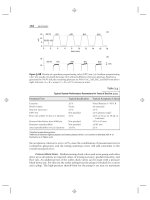
Unfortunately, similar to the earlier cases, the satellite signal will be
partially blocked as the pit deepens (see Figure 9.3). As such, in deep
open-pit mining, GPS alone cannot be used reliably for mining position-
ing. One promising system that can augment GPS to ensure high-accuracy
positioning at all times is the pseudolite (short for pseudosatellite) system.
A pseudolite is a ground-based electronic device that transmits a GPS-like
signal (code, carrier frequency, and data message), which can be acquired
by a GPS receiver. Unlike GPS, which uses atomic clocks onboard the
satellites, pseudolites typically use low-cost crystal clocks to generate the
signal [9].
The addition of pseudolite signals improves both system availability
and geometry. The number and locations of the pseudolites can be
GPS Integration 123
GPS
Pseudolite
GPS
GPS
GPS
Figure 9.3 GPS/pseudolite integration.
TEAMFLY
Team-Fly
®
optimized to ensure the best performance of the system. The vertical dilu-
tion of precision, in particular, can be improved dramatically, which leads
to improved accuracy for the height component. Another advantage of
using the pseudolites is that, being ground-based transmitters, their signals
are not affected by the ionosphere. Pseudolites, however, suffer from a
number of drawbacks that must be overcome to ensure high-accuracy
positioning. The first is known as the near-far problem, which results
from the variation in the received pseudolite signal power as the receiver-
pseudolite distance changes. The closer the receiver to the pseudolite trans-
mitter, the higher the signal power, and vice versa. This problem does not
exist with GPS-only positioning, as the received GPS signal power remains
almost constant, because the satellite-receiver distance does not change
significantly. Consequently, in GPS/pseudolite integration, if the pseudo-
lite signal is much stronger than the other pseudolite and GPS signals, it
may overwhelm the other signals and jam the receiver. This is what is
known as the near problem. However, if the pseudolite signal is much
weaker, the receiver may not be able to track it, which is known as the far
problem. Transmitting the pseudolite signal in short pulses with a low duty
cycle may, however, minimize the effect of the near-far problem [9].
The use of inaccurate clocks to generate the pseudolite signal causes
synchronization error in the sampling time. This error will cause a range
error, even if double differences are formed. A possible solution to this
problem is through the use of a content-free data message of a master pseu-
dolite. Another problem that requires the pseudolite users attention is the
multipath error. Pseudolite multipath error occurs as a result of reflected
signals from objects surrounding the antennas of both the receiver and the
transmitter. Some researchers have suggested the use of patterned anten-
nas as a feasible way of reducing the multipath effect. Unlike GPS-only
positioning where ephemeris errors do not affect the position solution sig-
nificantly, errors in the pseudolite coordinates will be propagated into the
solution, causing large positioning errors. This is caused by the relatively
short receiver-pseudolite separation [10]. Careful calibration of the pseu-
dolite antenna location solves this problem.
It should be pointed out that the application of the integrated GPS/
pseudolite system in not limited to deep open-pit mining. Such an inte-
grated system has been successfully used in precise aircraft landing, defor-
mation monitoring, and other applications. Being similar in principle to
GPS, pseudolite-only positioning has the potential of being the system of
124 Introduction to GPS
the future for indoor applications, such as underground mining (see
Figure 9.3). A challenging problem to overcome, however, is the pseudolite
location problem.
9.6 GPS/cellular integration
Cellular communication technology is becoming widely accepted
throughout the world. Both the number of subscribers and the cellular
coverage areas are increasing continuously. In addition, more advanced
digital cellular coverage is on the rise, allowing voice and data to be mixed
seamlessly. This makes the cellular system very attractive to a number of
markets, including emergency 911, AVL, and RTK GPS.
A major limitation with the current cellular system, however, is its
ability to precisely determine where a call was originated [11]. Although
this limitation is not critical for applications like RTK GPS, it is of utmost
importance for other applications such as emergency 911 and AVL. In the
United States, for example, about one-third of all emergency 911 calls
come from cellular phones. Of these, nearly one-fourth cannot describe
their location precisely, which makes it very difficult for an operator to
effectively send out assistance. As such, the U.S. Federal Communica-
tions Commission (FCC) has made it mandatory that, as of October
2001, wireless emergency 911 callers must be located with an accuracy of
125m (67% probability level) or better [11].
To meet the FCC location requirement, wireless network operators
can either use the network-based location or the handset-based location.
Most network-based caller location systems employ either the time-
difference of arrival (TDOA) approach or the angle of arrival (AOA)
approach to determine the callers location. The former measures the dif-
ferences in the arrival times of an emergency 911 signal at the cell sites or
base stations. The callers location can be determined if the signal is
received at a minimum of three base stations. Obviously, time synchroni-
zation is essential with this technique, which can be ensured by equipping
each cell site with a GPS timing receiver. The second technique, the AOA,
uses phased-array antennas to compute the angles at which the signal
arrives at the base stations. A minimum of two sites is required to compute
the callers location with this method. As both the TDOA and AOA
GPS Integration 125
methods have advantages and drawbacks, some network operators com-
bine the two methods [11].
Handset-based location technology integrates GPS with cellular com-
munication through the installation of a GPS chipset in the handset of the
wireless phone. With selective availability being turned off permanently,
this technology would locate the wireless emergency 911 callers with an
accuracy that exceeds the FCC requirement by a factor of ten. Unlike
network-based technology, handset-based location technology is very sim-
ple to implement and does not require the installation of additional equip-
ment at the base stations (e.g., GPS timing receivers). One of the drawbacks
of the handset-based location technology, however, is that only new cellu-
lar phones can be equipped with GPS. In addition, the GPS signal is very
weak to be received inside buildings. This limitation, however, could be
efficiently overcome in the near future with the development of integrated
GPS/MEMS technology, described in Section 9.3.
In the near future, the development of a new generation of cellular
technology, the 3G wideband digital networks, will be completed. The 3G
cellular technology supports voice, high-speed data, and multimedia appli-
cations. In addition, this technology uses common global standards, which
not only reduces the operational cost but also makes the system useable
worldwide. Moreover, with this new technology, devices can be turned on
all the time for data transmission, as subscribers pay for the packets of data
they receive/transmit.
The advances in the wireless communication and callers location
technologies discussed earlier will greatly impact a number of industries.
The vehicle navigation market, for example, is expected to greatly benefit
from the advances in wireless communication, location, and Internet tech-
nologies (see Section 10.11 for details about vehicle navigation). Currently,
vehicles use complex systems that integrate location technology with in-car
computer navigation systems containing electronic digital road maps and
other related information. Clearly, the in-car system will not be aware of
any real-world changes in the navigation systems database (e.g., a change
in the traffic direction). With the availability of wireless Internet service,
however, an up-to-date database residing at a central location could be
accessed by drivers, eliminating the need for a complex in-car computer
navigation system. Furthermore, with the availability of a precise location
system, drivers could customize the information they need according to
their locations, such as turn-by-turn navigation, traffic information, and
126 Introduction to GPS
local weather conditions. This method is simple, cost-effective, and flexi-
ble, and has the potential of being the way of the future.
References
[1] Elfick, M., et al., Elementary Surveying, 8th ed., New York: HarperCollins,
1994.
[2] Ashtech Inc., Reliance Field Asset Management Tools, Magellan
Corporation, Santa Clara, CA, 2001.
[3] Laser Technology Inc., Survey Laser For Forestry. PowerPoint
Presentation, accessed July 18, 2001, />downloads.html.
[4] Madhukar, B. R., et al., GPS-DR Integration Using Low Cost Sensors,
Proc. ION GPS-99, 12th Intl. Technical Meeting, Satellite Division, Institute
of Navigation, Nashville, TN, September 1417, 1999, pp. 537544.
[5] Kaplan, E., Understanding GPS: Principles and Applications, Norwood, MA:
Artech House, 1996.
[6] Schwarz, K. P., and N. El-Sheimy, Future Positioning and Navigation
(POS/NAV) Technologies Technical Study, Study performed under
Scientific Services Agreement with U.S. Topographic Engineering Center,
Fort Belvoir, VA, March 1999.
[7] May, M. B., Inertial Navigation and GPS, GPS World,Vol.4,No.9,
September 1993, pp. 5666.
[8] El-Rabbany, A., Mining Positioning, Proc. Smart Systems for Mineral
Resources Workshop, Toronto, Ontario, February 14, 2001.
[9] Cobb, S., and M. OConnor, Pseudolites: Enhancing GPS with
Ground-Based Transmitters, GPS World, Vol. 9, No. 3, March 1998,
pp. 5560.
[10] Wang, J., et al., Integrating GPS and Pseudolite Signals for Position and
Attitude Determination: Theoretical Analysis and Experiment Results,
Proc. ION GPS 2000, 13th Intl. Technical Meeting, Satellite Division,
Institute of Navigation, Salt Lake City, UT, September 1922, 2000,
pp. 22522262.
[11] Driscoll, C., Wireless Caller Location Systems, GPS World,Vol.9,No.
10, October 1998, pp. 4449.
GPS Integration 127