Switching Theory: Architecture and Performance in Broadband ATM Networks phần 5 pot
Bạn đang xem bản rút gọn của tài liệu. Xem và tải ngay bản đầy đủ của tài liệu tại đây (492.8 KB, 30 trang )
160
The ATM Switch Model
are unbuffered (
IN queueing
). In this last case input and output queueing, whenever adopted,
take place at IPC and OPC, respectively, whereas shared queueing is accomplished by means
of additional hardware associated with the IN.
In general two types of conflict characterize the switching operation in the interconnection
network in each slot, the
internal conflict
s and the
external conflicts
. The former occur when two
I/O paths compete for the same internal resource, that is the same interstage link in a multi-
stage arrangement, whereas the latter take place when more than
K
packets are switched in the
same slot to the same OPC (we are assuming for simplicity ). An ATM interconnec-
tion network with speed-up
K
is said to be non-blocking (
K
-rearrangeable
according to the definition given in Section 3.2.3) if it guarantees absence of internal conflicts
for any arbitrary switching configuration free from external conflicts for the given network
speed-up value
K
. That is a non-blocking IN is able to transfer to the OPCs up to
N
packets
per slot, in which at most
K
of them address the same switch output. Note that the adoption
of output queues either in an SE or in the IN is strictly related to a full exploitation of the
speed-up: in fact, a structure with does not require output queues, since the output
interface is able to transmit downstream one packet per slot. Whenever queues are placed in
different elements of the ATM switch (e.g., SE queueing, as well as input or shared queueing
coupled with output queueing in IN queueing), two different internal transfer modes can be
adopted:
•
backpressure
(BP), in which by means of a suitable backward signalling the number of pack-
ets actually switched to each downstream queue is limited to the current storage capability
of the queue; in this case all the other head-of-line (HOL) cells remain stored in their
respective upstream queue;
•
queue loss
(QL), in which cell loss takes place in the downstream queue for those HOL
packets that have been transmitted by the upstream queue but cannot be stored in the
addressed downstream queue.
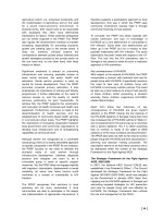
Figure 5.2. Model of ATM switch
0
N-1
0
N-1
K
o
K
o
IPC OPC
IN
K
i
K
i
K
i
1=
NN× KN≤()
K 1=
sw_mod Page 160 Tuesday, November 18, 1997 4:31 pm
The Switch Model
161
The main functions of the port controllers are:
•
rate matching between the input/output channel rate and the switching fabric rate;
•
aligning cells for switching (IPC) and transmission (OPC) purposes (this requires a tempo-
rary buffer of one cell);
•
processing the cell received (IPC) according to the supported protocol functionalities at the
ATM layer; a mandatory task is the
routing
(switching) function, that is the allocation of a
switch output and a new VPI/VCI to each cell, based on the VCI/VPI carried by the
header of the received cell;
•
attaching (IPC) and stripping (OPC) a self-routing label to each cell;
•
with IN queueing, storing (IPC) the packets to be transmitted and probing the availability
of an I/O path through the IN to the addressed output, by also checking the storage capa-
bility at the addressed output queue in the BP mode, if input queueing is adopted; queue-
ing (OPC) the packets at the switch output, if output queueing is adopted.
An example of ATM switching is given in Figure 5.3. Two ATM cells are received by the
ATM node
I
and their VPI/VCI labels,
A
and
C
, are mapped in the input port controller onto
the new VPI/VCI labels
F
and
E
; the cells are also addressed to the output links
c
and
f
, respec-
tively. The former packet enters the downstream switch
J
where its label is mapped onto the
new label
B
and addressed to the output link
c
. The latter packet enters the downstream node
K
where it is mapped onto the new VPI/VCI
A
and is given the switch output address
g
. Even
if not shown in the figure, usage of a self-routing technique for the cell within the intercon-
nection network requires the IPC to attach the address of the output link allocated to the
virtual connection to each single cell. This self-routing label is removed by the OPC before the
cell leaves the switching node.
The traffic performance of ATM switches will be analyzed in the next sections by referring
to an offered
uniform random traffic
in which:
•
packet arrivals at the network inlets are independent and identically distributed Bernoulli
processes with
p
indicating the probability that a network inlet receives a
packet in a generic slot;
•
a network outlet is randomly selected for each packet entering the network with uniform
probability .
Note that this rather simplified pattern of offered traffic completely disregards the application
of connection acceptance procedure of new virtual calls, the adoption of priority among traffic
classes, the provision of different grade of services to different traffic classes, etc. Nevertheless,
the uniform random traffic approach enables us to develop more easily analytical models for an
evaluation of the traffic performance of each solution compared to the others. Typically three
parameters are used to describe the switching fabric performance, all of them referred to
steady-state conditions for the traffic:
•
Switch throughput
ρ
: the normalized amount of traffic carried by the switch
expressed as the utilization factor of its input links; it is defined as the probability that a
packet received on an input link is successfully switched and transmitted by the addressed
switch output; the maximum throughput , also referred to as
switch capacity
, indicates
the load carried by the switch for an offered load .
0 p 1≤<()
1 N⁄
0 ρ 1≤<()
ρ
max
p 1=
sw_mod Page 161 Tuesday, November 18, 1997 4:31 pm
ATM Switch Taxonomy 163
5.2. ATM Switch Taxonomy
As already mentioned, classifying all the different ATM switch architectures that have been
proposed or developed is a very complicated and arduous task, as the key parameters for
grouping together and selecting the different structures are too many. As a proof, we can men-
tion the taxonomies presented in two surveys of ATM switches presented some years ago.
Ahmadi and Denzel [Ahm89] identified six different classes of ATM switches according to
their internal structure: banyan and buffered banyan-based fabrics, sort-banyan-based fabrics,
fabrics with disjoint path topology and output queueing, crossbar-based fabrics, time division
fabrics with common packet memory, fabrics with shared medium. Again the technological
aspects of the ATM switch fabric were used by Tobagi [Tob90] to provide another survey of
ATM switch architectures which identifies only three classes of switching fabrics: shared mem-
ory, shared medium and space-division switching fabrics. A further refinement of this
taxonomy was given by Newman [New92], who further classified the space-division type
switches into single-path and multiple-path switches, thus introducing a non-technological
feature (the number of I/O paths) as a key of the classification.
It is easier to identify a more general taxonomy of ATM switches relying both on the func-
tional relationship set-up between inlets and outlets by the switch and on the technological
features of the switching architecture, and not just on these latter properties as in most of the
previous examples. We look here at switch architectures that can be scaled to any reasonable
size of input/output ports; therefore our interest is focused onto multistage structures which
own the distributed switching capability required to switch the enormous amounts of traffic
typical of an ATM environment.
Multistage INs can be classified as blocking or non-blocking. In the case of blocking intercon-
nection networks, the basic IN is a banyan network, in which only one path is provided
between any inlet and outlet of the switch and different I/O paths within the IN can share
some interstage links. Thus the control of packet loss events requires the use of additional tech-
niques to keep under control the traffic crossing the interconnection network. These
techniques can be either the adoption of a packet storage capability in the SEs in the basic ban-
yan network, which determines the class of minimum-depth INs, or the usage of deflection
routing in a multiple-path IN with unbuffered SEs, which results in the class of arbitrary-depth
INs. In the case of non-blocking interconnection networks different I/O paths are available, so
that the SEs do not need internal buffers and are therefore much simpler to be implemented (a
few tens of gates per SE). Nevertheless, these INs require more stages than blocking INs.
Two distinctive technological features characterizing ATM switches are the buffers config-
uration and the number of switching planes in the interconnection network. Three
configurations of cell buffering are distinguished with reference to each single SE or to the
whole IN, that is input queueing (IQ), output queueing (OQ) and shared queueing (SQ). The buffer
is placed inside the switching element with SE queueing, whereas unbuffered SEs are used
with IN queueing, the buffer being placed at the edges of the interconnection network. It is
important to distinguish also the architectures based on the number of switch planes it
includes, that is single-plane structures and parallel plane structures in which at least two
switching planes are equipped. It is worth noting that adopting parallel planes also means that
sw_mod Page 163 Tuesday, November 18, 1997 4:31 pm
164 The ATM Switch Model
we adopt a queueing strategy that is based on, or anyway includes, output queueing. In fact
the adoption of multiple switching planes is equivalent from the standpoint of the I/O func-
tions of the overall interconnection network to accomplishing a speed-up equal to the number
of planes. As already discussed in Section 5.1, output queueing is mandatory in order to con-
trol the cell loss performance when speed-up is used.
A taxonomy of ATM switch architectures, which tries to classify the main ATM switch
proposals that have appeared in the technical literature can be now proposed. By means of the
four keys just introduced (network blocking, network depth, number of switch planes and
queueing strategy), the taxonomy of ATM interconnection network given in Figure 5.4 is
obtained which only takes into account the meaningful combinations of the parameters, as
witnessed by the switch proposals appearing in the technical literature. Four ATM switch
classes have been identified:
• blocking INs with minimum depth: the interconnection network is blocking and the number
of switching stages is the minimum required to reach a switch outlet from a generic switch
inlet; with a single plane, SE queueing is adopted without speed-up so that only one path
is available per I/O pair; with parallel planes, IN queueing and simpler unbuffered SEs are
used; since a speed-up is accomplished in this latter case, output queueing is adopted either
alone (OQ) or together with input queueing (IOQ);
• blocking INs with arbitrary depth: IN queueing and speed-up are adopted in both cases of sin-
gle and parallel planes; the interconnection network, built of unbuffered SEs, is blocking
but makes available more than one path per I/O pair by exploiting the principle of deflec-
tion routing; output queueing (OQ) is basically adopted;
• non-blocking IN with single queueing: the interconnection network is internally non-blocking
and IN queueing is used with buffer being associated with the switch inputs (IQ), with the
switch outputs (OQ) or shared among all the switch inlets and outlets (SQ);
• non-blocking IN with multiple queueing: the IN is non-blocking and a combined use of two
IN queueing types is adopted (IOQ, SOQ, ISQ) with a single-plane structure; an IN with
parallel planes is adopted only with combined input/output queueing (IOQ).
A chapter is dedicated in the following to each of these four ATM switch classes, each dealing
with both architectural and traffic performance aspects.
Limited surveys of ATM switches using at least some of the above keys to classify the archi-
tectures have already appeared in the technical literature. Non-blocking architectures with
single queueing strategy are reviewed in [Oie90b], with some performance issues better inves-
tigated in [Oie90a]. Non-blocking ATM switches with either single or multiple queueing
strategies are described in terms of architectures and performance in [Pat93]. A review of
blocking ATM switches with arbitrary depth IN is given in [Pat95].
sw_mod Page 164 Tuesday, November 18, 1997 4:31 pm
Chapter 6
ATM Switching with
Minimum-Depth Blocking Networks
Architectures and performance of interconnection networks for ATM switching based on the
adoption of banyan networks are described in this chapter. The interconnection networks pre-
sented now have the common feature of a
minimum depth
routing network, that is the path(s)
from each inlet to every outlet crosses the minimum number of routing stages required to
guarantee full accessibility in the interconnection network and to exploit the self-routing
property. According to our usual notations this number
n
is given by for a net-
work built out of switching elements. Note that a packet can cross more than
n
stages where switching takes place, when distribution stages are adopted between the switch
inlets and the
n
routing stages. Nevertheless, in all these structures the switching result per-
formed in any of these additional stages does not affect in any way the self-routing operation
taking place in the last
n
stages of the interconnection network. These structures are inherently
blocking as each interstage link is shared by several I/O paths. Thus packet loss takes place if
more than one packet requires the same outlet of the switching element (SE), unless a proper
storage capability is provided in the SE itself.
Unbuffered banyan networks are the simplest self-routing structure we can imagine. Nev-
ertheless, they offer a poor traffic performance. Several approaches can be considered to
improve the performance of banyan-based interconnection networks:
1.
Replicating a banyan network into a set of parallel networks in order to divide the offered
load among the networks;
2.
Providing a certain multiplicity of interstage links, so as to allow several packets to share the
interstage connection;
3.
Providing each SE with internal buffers, which can be associated either with the SE inlets
or to the SE outlets or can be shared by all the SE inlets and outlets;
4.
Defining handshake protocols between adjacent SEs in order to avoid packet loss in a buff-
ered SE;
nN
b
log=
NN× bb×
This document was created with FrameMaker 4.0.4
ban_mindep Page 167 Monday, November 10, 1997 8:22 pm
Switching Theory: Architecture and Performance in Broadband ATM Networks
Achille Pattavina
Copyright © 1998 John Wiley & Sons Ltd
ISBNs: 0-471-96338-0 (Hardback); 0-470-84191-5 (Electronic)
168
ATM Switching with Minimum-Depth Blocking Networks
5.
Providing external queueing when replicating unbuffered banyan networks, so that multi-
ple packets addressing the same destination can be concurrently switched with success.
Section 6.1 describes the performance of the unbuffered banyan networks and describes
networks designed according to criteria 1 and 2; therefore networks built of a single banyan
plane or parallel banyan planes are studied. Criteria 3 and 4 are exploited in Section 6.2, which
provides a thorough discussion of banyan architectures suitable to ATM switching in which
each switching element is provided with an internal queueing capability. Section 6.3 discusses
how a set of internally unbuffered networks can be used for ATM switching if queueing is
available at switch outlets with an optional queueing capacity associated with network inlets
according to criterion 5. Some final remarks concerning the switch performance under
offered traffic patterns other than random and other architectures of ATM switches based on
minimum-depth routing networks are finally given in Section 6.4.
6.1. Unbuffered Networks
The class of unbuffered networks is described now so as to provide the background necessary
for a satisfactory understanding of the ATM switching architectures to be investigated in the
next sections. The structure of the basic banyan network and its traffic performance are first
discussed in relation to the behavior of the crossbar network. Then improved structures using
the banyan network as the basic building block are examined: multiple banyan planes and mul-
tiple interstage links are considered.
6.1.1. Crossbar and basic banyan networks
The terminology and basic concepts of crossbar and banyan networks are here recalled and the
corresponding traffic performance parameters are evaluated.
6.1.1.1. Basic structures
In principle, we would like any interconnection network (IN) to provide an optimum perfor-
mance, that is maximum throughput and minimum packet loss probability . Packets are
lost in general for two different reasons in unbuffered networks: conflicts for an internal IN
resource, or
internal conflicts
, and conflicts for the same IN outlet, or
external conflicts
. The loss
due to external conflicts is independent of the particular network structure and is unavoidable
in an unbuffered network. Thus, the “ideal” unbuffered structure is the
crossbar network
(see
Section 2.1) that is free from internal conflicts since each of the crosspoints is dedicated to
each specific I/O couple.
An banyan network built out of SEs includes
n
stages of SEs in which
. An example of a banyan network with Baseline topology and size is
given in Figure 6.1a for and in Figure 6.1b for . As already explained in
Section 2.3.1, internal conflicts can occur in banyan networks due to the link commonality of
different I/O paths. Therefore the crossbar network can provide an upper bound on through-
ρπ
N
2
NN× bb× Nb⁄
nN
b
log= N 16=
b 2=
b 4=
ban_mindep Page 168 Monday, November 10, 1997 8:22 pm
170
ATM Switching with Minimum-Depth Blocking Networks
and dilated banyan networks to be described next. Further extensions of these results are
reported by Szymanski and Hamacker. [Szy87].
The analysis given here, which summarizes the main results provided in these papers, relies
on a simplifying assumption, that is the statistical independence of the events of packet arrivals
at SEs of different stages. Such a hypothesis means overestimating the offered load stage by
stage, especially for high loads [Yoo90].
The throughput and loss performance of the basic unbuffered banyan network,
which thus includes
n
stages of SEs, can be evaluated by recursive analysis of the load on
adjacent stages of the network. Let indicate the probability that a generic
outlet of an SE in stage
i
is “busy”, that is transmits a packet ( denotes the external load
offered to the network). Since the probability that a packet is addressed to a given SE outlet
is , we can easily write
(6.2)
Thus, throughput and loss are given by
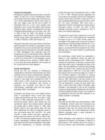
Figure 6.2. Switch capacity of a banyan network
b
n
b
n
×
bb×
p
i
i 1 … n,,=()
p
0
1 b⁄
p
0
p=
p
i
11
p
i 1–
b
–
b
–= i 1 … n,,=()
ρ p
n
=
π 1
p
n
p
0
–=
0.2
0.3
0.4
0.5
0.6
0.7
0.8
1 10 100 1000 10000
p=1.0
Maximum throughput,
ρ
max
Switch size, N
Crossbar
b=8
b=4
b=2
ban_mindep Page 170 Monday, November 10, 1997 8:22 pm
Unbuffered Networks
171
The switch capacity, , of a banyan network (Equation 6.2) with different sizes
b
of the
basic switching element is compared in Figure 6.2 with that provided by a crossbar network
(Equation 6.1) of the same size. The maximum throughput of the banyan network decreases as
the switch size grows, since there are more packet conflicts due to the larger number of net-
work stages. For a given switch size a better performance is given by a banyan network with a
larger SE: apparently as the basic
SE
grows, less stages are needed to build a banyan net-
work with a given size
N
.
An asymptotic estimate of the banyan network throughput is computed in [Kru83]
which provides an upper bound of the real network throughput and whose accuracy is larger
for moderate loads and large networks. Figure 6.3 shows the accuracy of this simple bound for
a banyan network loaded by three different traffic levels. The bound overestimates the real net-
work throughput and the accuracy increases as the offered load
p
is lowered roughly
independently of the switch size.
It is also interesting to express
π
as a function of the loss probability
occurring in the single stages. Since packets can be lost in general at any stage
due to conflicts for the same SE outlet, it follows that
Figure 6.3. Switch capacity of a banyan network
ρ
max
bb×
ρ
2b
b 1–()n
2b
p
+
≅
0.1
0.2
0.3
0.4
0.5
0.6
0.7
0.8
0.9
1 10 100 1000 10000
b=2
Crossbar
Analysis
Bound
Network throughput
Switch size, N
p=0.5
p=0.75
p=1.0
π
i
1 p
i
p
i 1–
⁄–=
i 1 … n,,=()
π 11π
i
–()
i 1=
n
∏
–=
ban_mindep Page 171 Monday, November 10, 1997 8:22 pm
172 ATM Switching with Minimum-Depth Blocking Networks
or equivalently by applying the theorem of total probability
Therefore the loss probability can be expressed as a function of the link load stage by stage as
(6.3)
For the case of the stage load given by Equation 6.2 assumes an expression that is
worth discussion, that is
(6.4)
Equation 6.4 says that the probability of a busy link in stage i is given by the probability of
a busy link in the previous stage decreased by the probability that both the SE inlets are
receiving a packet ( ) and both packets address the same SE outlet . So, the loss
probability with SEs given by Equation 6.3 becomes
(6.5)
6.1.2. Enhanced banyan networks
Interconnection networks based on the use of banyan networks are now introduced and their
traffic performance is evaluated.
6.1.2.1. Structures
Improved structures of banyan interconnection networks were proposed [Kum86] whose basic
idea is to have multiple internal paths per inlet/outlet pair. These structures either adopt multi-
ple banyan networks in parallel or replace the interstage links by multiple parallel links.
An interconnection network can be built using K parallel networks
(planes) interconnected to a set of N splitters and a set of N combiners through
suitable input and output interconnection patterns, respectively, as shown in Figure 6.4. These
structures are referred to as replicated banyan networks (RBN), as the topology in each plane is
banyan or derivable from a banyan structure. The splitters can distribute the incoming traffic in
different modes to the banyan networks; the main techniques are:
• random loading (RL),
• multiple loading (ML),
• selective loading (SL).
ππ
1
π
i
1 π
h
–()
h 1=
i 1–
∏
i 2=
n
∑
+=
ππ
1
π
i
1 π
h
–()
h 1=
i 1–
∏
i 2=
n
∑
+ 1
p
1
p
0
– 1
p
i
p
i 1–
–
p
h
p
h 1–
h 1=
i 1–
∏
i 2=
n
∑
+
p
i 1–
p
i
–
p
0
i 1=
n
∑
== =
b 2=
p
i
11
p
i 1–
2
–
2
– p
i 1–
1
4
p
i 1–
2
–== i 1 … n,,=()
i 1–
p
i 1–
2
14⁄()
22×
π
p
i 1–
p
i
–
p
0
i 1=
n
∑
1
4
p
i 1–
2
p
0
i 1=
n
∑
==
NN× NN×
1 K× K 1×
ban_mindep Page 172 Monday, November 10, 1997 8:22 pm
174 ATM Switching with Minimum-Depth Blocking Networks
the proper plane using the first k digits (in base b) of the routing tag. The example in
Figure 6.6 refers to the case of , and in which the truncated banyan
network has the reverse Baseline topology with the last stage removed. Note that the connec-
tion between each banyan network and its combiners is a perfect shuffle (or EGS) pattern. The
target of this technique is to reduce the number of packet conflicts by jointly reducing the
offered load per plane and the number of conflict opportunities.
Providing multiple paths per I/O port, and hence reducing the packet loss due to conflicts
for interstage links, can also be achieved by adopting a multiplicity of
physical links for each “logical” interstage link of a banyan network (see Figure 4.10 for
, and ). Now up to packets can be concurrently exchanged
between two SEs in adjacent stages. These networks are referred to as dilated banyan networks
(DBN). Such a solution makes the SE, whose physical size is now , much more
complex than the basic SE. In order to drop all but one of the packets received by the
last stage SEs and addressing a specific output, combiners can be used that concentrate
the physical links of a logical outlet at stage n onto one interconnection network output.
However, unlike replicated networks, this concentration function could be also performed
directly by each SE in the last stage.
Figure 6.5. RBN with random or multiple loading
N-1
1
0
1xKNxNKx1
#0
#1
#(K-1)
N-1
1
0
Banyan
networks
N 16= b 2= K
s
2=
KK
d
= K
d
2≥()
N 16= b 2= K
d
2= K
d
2K
d
2K
d
×
22×
K
d
1×
K
d
ban_mindep Page 174 Monday, November 10, 1997 8:22 pm
176 ATM Switching with Minimum-Depth Blocking Networks
planes increases the probability that at least one copy reaches the addressed output, as the
choice for packet discarding is random in each plane. This advantage is compensated by the
drawback of a higher load in each plane, which implies an increased number of collision (and
loss) events.
With selective loading, packet loss events occur only in stages of each plane and the
offered load per plane is still . The packet loss probability is again given by
with the switch throughput provided by
since each combiner can receive up to K packets from the plane it is attached to.
In dilated networks each SE has size , but not all physical links are active, that is
enabled to receive packets. SEs have 1 active inlet and b active outlets per logical port at stage
1, b active inlets and active outlets at stage 2, K active inlets and K active outlets from stage
k onwards . The same recursive load computation as described for the basic ban-
yan network can be adopted here taking into account that each SE has bK physical inlets and b
logical outlets, and that not all the physical SE inlets are active in stages 1 through . The
event of m packets transmitted on a tagged link of an SE in stage i , whose proba-
bility is , occurs when packets are received by the SE from its b upstream SEs and
m of these packets address the tagged logical outlet. If denotes the probability that m
packets are received on a tagged inlet an SE in stage 1, we can write
The packet loss probability is given as usual by with the throughput provided by
The switch capacity, , of different configurations of banyan networks is shown in
Figure 6.7 in comparison with the crossbar network capacity. RBNs with random and selec-
tive loading have been considered with and , respectively. A dilated
banyan network with link dilation factors has also been studied. RBN with ran-
dom and selective loading give a comparable throughput performance, the latter behaving a
little better. A dilated banyan network with dilation factor behaves much better than an
RBN network with replication factor . The dilated banyan network with
nk–
p
0
K⁄π1 ρ p⁄–=
ρ 11p
nk–
–()
K
–=
bK bK×
b
2
kK
b
log=()
k 1–
1 in≤≤()
p
i
m()
j
m≥
p
0
m()
p
0
m()
1 p – m 0=
pm1=
0 m 1>
=
p
i
m()
j
m
1
b
m
1
1
b
–
jm–
p
i 1–
m
1
()…p
i 1–
m
b
()
m
1
… m
b
++ j=
∑
jm=
bK
∑
mK<()
j
h
hm=
j
∑
1
b
h
1
1
b
–
jh–
p
i 1–
m
1
()…p
i 1–
m
b
()
m
1
… m
b
++ j=
∑
jm=
bK
∑
mK=()
=
π 1 ρ p⁄–=
ρ 1 p
n
0()–=
ρ
max
K
r
24,= K
s
24,=
K
d
24,=
K
d
KK
d
= K
d
4=
ban_mindep Page 176 Monday, November 10, 1997 8:22 pm
178 ATM Switching with Minimum-Depth Blocking Networks
put queueing b physical queues are available in the SE, whereas only one is available with
shared queueing. In this latter case the buffer is said to include b logical queues, each holding
the packets addressing a specific SE outlet. In all the buffered SE structure considered here we
assume a FIFO cell scheduling, as suggested by simplicity requirements for hardware
implementation.
Various internal protocols are considered in our study, depending on the absence or pres-
ence of signalling between adjacent stages to enable the downstream transmission of a packet
by an SE. In particular we define the following internal protocols:
• backpressure (BP): signals are exchanged between switching elements in adjacent stages
so that the generic SE can grant a packet transmission to its upstream SEs only within the
current idle buffer capacity. The upstream SEs enabled to transmit are selected according to
the acknowledgment or grant mode, whereas the number of idle buffer positions is deter-
mined based on the type of backpressure used, which can be either global (GBP) or local
(LBP). These operations are defined as follows:
— acknowledgment (ack): the generic SE in stage i issues as many requests as
the number of SE outlets addressed by head-of-line (HOL) packets, each transmitted to
the requested downstream SE. In response, each SE in stage i enables the
transmission by means of acknowledgments to all the requesting upstream SEs, if their
number does not exceed its idle buffer positions, determined according to the GBP or
LBP protocol; otherwise the number of enabled upstream SEs is limited to those
needed to saturate the buffer;
— grant (gr): without receiving any requests, the generic SE in stage i grants
the transmission to all the upstream SEs, if its idle buffer positions, , are at least b;
otherwise only upstream SEs are enabled to transmit; unlike the BP-ack protocol,
the SE can grant an upstream SE whose corresponding physical or logical queue is
empty with the BP-gr operations;
— local backpressure (LBP): the number of buffer places that can be filled in the
generic SE in stage i at slot t by upstream SEs is simply given by the num-
ber of idle positions at the end of the slot ;
— global backpressure (GBP): the number of buffer places that can be filled in the
generic SE in stage i at slot t by upstream SEs is given by the number of
idle positions at the end of the slot increased by the number of packets that are
going to be transmitted by the SE in the slot t;
• queue loss (QL): there is no exchange of signalling information within the network, so
that a packet per non-empty physical or logical queue is always transmitted downstream by
each SE, independent of the current buffer status of the destination SE; packet storage in
the SE takes place as long as there are enough idle buffer positions, whereas packets are lost
when the buffer is full.
From the above description it is worth noting that LBP and GBP, as well as BP-ack and
BP-gr, result in the same number of upstream acknowledgment/grant signals by an SE if at
least b positions are idle in its buffer at the end of the preceding slot. Moreover, packets can be
lost for queue overflow only at the first stage in the BP protocols and at any stage in the QL
protocol. In our model the selection of packets to be backpressured in the upstream SE (BP) or
to be lost (QL) in case of buffer saturation is always random among all the packets competing
1 in<≤()
1 in≤<()
1 in≤<()
n
idle
n
idle
1 in≤<()
t 1–
1 in≤<()
t 1–
ban_mindep Page 178 Monday, November 10, 1997 8:22 pm
Networks with a Single Plane and Internal Queueing 179
for the access to the same buffer. Note that such general description of the internal protocols
applied to the specific type of queueing can make meaningless some cases.
The implementation of the internal backpressure requires additional internal resources to
be deployed compared to the absence of internal protocols (QL). Two different solutions can
be devised for accomplishing interstage backpressure, that is in the space domain or in the time
domain. In the former case additional internal links must connect any couple of SEs interfaced
by interstage links. In the latter case the interstage links can be used on a time division base to
transfer both the signalling information and the ATM cells. Therefore an internal bit rate, ,
higher than the link external rate, C (bit/s), is required. With the acknowledgment BP we
have a two-phase signalling: the arbitration phase where all the SEs concurrently transmit their
requests downstream and the enable phase where each SE can signal upstream the enabling sig-
nal to a suitable number of requesting SEs. The enable phase can be accomplished
concurrently by all SEs with the local backpressure, whereas it has be a sequential operation
with global backpressure. In this last case an SE needs to know how many packets it is going to
transmit in the current slot to determine how many enable signals can be transmitted
upstream, but such information must be first received by the downstream SEs. Thus the enable
phase of the BP-ack protocol is started by SEs in stage n and ends with the receipt of enable
signal by SEs in stage 1. Let and (bit) be the size of each downstream and upstream sig-
nalling packet, respectively, and (bit) the length of an information packet (cell). Then the
internal bit rate is for the QL protocol and for the BP protocol
where η denotes the switching overhead. This factor in the BP protocol with acknowledgment is
given by
(6.8)
In the BP protocol with grant we do not have any request phase and the only signalling is rep-
resented by the enable phase that is performed as in the case of the BP-ack protocol. Thus the
internal rate of the BP-gr protocol is given by Equation 6.8 setting .
The network is assumed to be loaded by purely random and uniform traffic; that is at stage 1:
1. A packet is received with the same probability in each time slot;
2. Each packet is given an outlet address that uniformly loads all the network outlets;
3. Packet arrival events at different inlets in the same time slots are mutually independent;
4. Packet arrival events at an inlet or at different inlets in different time slot are mutually inde-
pendent.
Even if we do not provide any formal proof, assumption 2 is likely to be true at every stage,
because of general considerations about flow conservation across stages. The independence
assumption 3 holds for every network stage in the QL mode, since the paths leading to the dif-
ferent inlets of an SE in stage i cross different SEs in stage (recall that one path through
the network connects each network inlet to each network outlet). Owing to the memory
C
i
l
d
l
u
l
c
C
i
C= C
i
1 η+()C=
η
l
d
n 1–()l
u
+
l
c
GBP
l
d
l
u
+
l
c
LBP
=
C
i
l
d
0=
j
i<
ban_mindep Page 179 Monday, November 10, 1997 8:22 pm
180 ATM Switching with Minimum-Depth Blocking Networks
device in each SE, the assumption 4, as well as the assumption 3 for the BP protocol, no
longer holds in stages other than the first. For simplicity requirements the assumption 3 is sup-
posed to be always true in all the stages in the analytical models to be developed later. In spite
of the correlation in packet arrival events at a generic SE inlet in stages 2 through n, our mod-
els assume independence of the state of SEs in different stages. Such a correlation could be
taken into account by suitably modelling the upstream traffic source loading each SE inlet.
Nevertheless, in order to describe simple models, each upstream source will be represented
here by means of only one parameter, the average load.
We assume independence between the states of SEs in the same stage, so that one SE per
stage is representative of the behavior of all the elements in the same stage ( will denote
such an element for stage i). For this reason the topology of the network, that is the specific
kind of banyan network, does not affect in any way the result that we are going to obtain. As
usual we consider banyan networks with switching elements, thus including
stages.
Buffered banyan networks were initially analyzed by Dias and Jump [Dia81], who only
considered asymptotic loads, and by Jenq [Jen83], who analyzed the case of single-buffered
input-queued banyan networks loaded by a variable traffic level. The analysis of buffered ban-
yan networks was extended by Kumar and Jump [Kum84], so as to include replicated and
dilated buffered structures. A more general analysis of buffered banyan networks was presented
by Szymanski and Shiakh [Szy89], who give both separate and combined evaluation of differ-
ent SE structures, such as SE input queueing, SE output queueing, link dilation. The analysis
given in this section for networks adopting SEs with input queueing or output queueing is
based on this last paper and takes into account the modification and improvements described
in [Pat91], mainly directed to improve the computational precision of network throughput and
cell loss. In particular, the throughput is only computed as a function of the cell loss probabil-
ity and not vice versa.
As far as networks with shared-queued SEs are concerned, some contributions initially
appeared in the technical literature [Hlu88, Sak90, Pet90], basically aiming at the study of a
single-stage network (one switching element). Convolutional approaches are often used that
assume mutual independence of the packet flows addressing different destinations. Analytical
models for multistage structures with shared-buffered SEs have been later developed in [Tur93]
and [Mon92]. Turner [Tur93] proposed a simple model in which the destinations of the pack-
ets in the buffer were assumed mutually independent. Monterosso and Pattavina [Mon92]
developed an exact Markovian model of the switching element, by introducing modelling
approximation only in the interstage traffic. The former model gave very inaccurate results,
whereas the latter showed severe limitation in the dimensions of the networks under study. The
model described here is the simplest of the three models described in [Gia94] in which the SE
state is always represented as a two-state variable. The other two more complex models therein,
not developed here, take into account the correlation of the traffic received at any stage other
than the first.
SE
i
NN×
bb×
nN
b
log=
ban_mindep Page 180 Monday, November 10, 1997 8:22 pm
Networks with a Single Plane and Internal Queueing 181
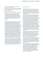
6.2.1. Input queueing
The functional structure of a SE with input queueing, shown in Figure 6.8 in the solu-
tion with additional interstage links for signalling purposes, includes two (local) queues, each
with capacity cells, and a controller. Each of the local queues, which interface directly
the upstream SEs, performs a single read and write operation per slot. The controller receives
signals from the (remote) queues of the downstream SEs and from the local queues when per-
forming the BP protocol. With this kind of queueing there is no need for an arbitration phase
with downstream signalling, since each queue is fed by only one upstream SE. Thus the BP
protocol can only be of the grant type. Nevertheless, arbitration must take place slot by slot by
the SE controller to resolve possible conflicts arising when more than one HOL cell of the
local queues addresses the same SE outlet.
Packet transmissions to downstream SEs (or network outlets) and packet receipt from
upstream SEs (or network inlets) take place concurrently in the SE at each time slot. For the
sake of better understanding the protocols QL and GBP, we can well imagine for an SE that
packet transmissions occur in the first half of the slot, whereas packet receipts take place in the
second half of the slot based on the empty buffer space at the end of the first phase. With the
LBP protocol there is no need for such decomposition as the amount of packets to be received
is independent of the packets to be transmitted in the slot. In such a way we can define a vir-
tual half of each time slot that separates transmissions from receipts.
In order to develop analytical models for the network, it turns out useful to define the fol-
lowing probability distributions to characterize the dynamic of the generic input queue of the
SE, the tagged queue:
• = Pr [the tagged queue at stage i at time t contains m packets];
• = Pr [the tagged queue at stage i at time t contains m packets if we consider to be
removed those packets that are going to be transmitted in the slot t];
• = Pr [an SE at stage i at time t offers a packet to a queue at stage ];
denoted the external offered load;
• = Pr [a packet offered by a queue at stage i at time t is actually transmitted by the
queue];
Figure 6.8. SE with input queueing
22×
BB
i
=
Controller
d
it,
m()
d'
it,
m()
a
it,
i 1+ a
0
p=
b
it,
ban_mindep Page 181 Monday, November 10, 1997 8:22 pm
182 ATM Switching with Minimum-Depth Blocking Networks
• = Pr [a packet offered by a queue at stage i at time t is selected for transmission].
Note that the denotes the probability distribution of the tagged queue at the half-
time slot if transmission and receipt of packets occur sequentially in the slot. The LBP protocol
does not require the definition of the distribution , as the ack/grant signals depend only
on the idle buffer space at the end of the last slot. Moreover, for the sake of simplicity, the fol-
lowing notation is used:
In the following, time-dependent variables without the subscript t indicate the steady-state
value assumed by the variable.
The one-step transition equations for the protocols QL and GBP describing the dynamic
of the tagged queue due first to cell transmissions and then to the cell receipts are easily
obtained:
The analogous equations for the LBP protocol with are
c
it,
d'
it,
m()
d'
it,
β Nip,,()
N
i
p
i
1 p–()
Ni–
=
d'
it,
0() d
it 1–,
1()b
it,
d
it 1–,
0()+=
d'
it,
h() d
it 1–,
h 1+()b
it,
d
it 1–,
h() 1 b
it,
–() 1 hB
i
1–≤≤()+=
d'
it,
B
i
() d
it 1–,
B
i
()1 b
it,
–()=
d
it,
0() d'
it,
0() 1 a
i 1– t,
–()=
d
it,
h() d'
it,
h 1–()a
i 1– t,
d'
it,
h() 1 a
i 1– t,
–() 1 hB
i
1–≤≤()+=
d
it,
B
i
() d'
it,
B
i
() d'
it,
B
i
1–()a
i 1– t,
+=
B
i
3≥
d
it,
0() d
it 1–,
1() 1 a
i 1– t,
–()b
it,
d
it 1–,
0() 1 a
i 1– t,
–()+=
d
it,
1() d
it 1–,
2() 1 a
i 1– t,
–()b
it,
d
it 1–,
1() a
i 1 t,–
b
it,
1 a
i 1– t,
–()1 b
it,
–()+[]
d
it 1–,
0()a
i 1 t,–
+
+
=
d
it,
h() d
it 1–,
h 1+()1 a
i 1– t,
–()b
it,
d
it 1–,
h() a
i 1 t,–
b
it,
1 a
i 1– t,
–()1 b
it,
–()+[]+=
d
it 1–,
h 1–()a
i 1 t,–
1 b
it,
–()
+
1 hB
i
1–<<()
d
it,
B
i
1–()d
it 1–,
B
i
()b
it,
d
it 1–,
B
i
1–()a
i 1 t,–
b
it,
1 a
i 1– t,
–()1 b
it,
–()+[]+=
d
it 1–,
B
i
2–()a
i 1 t,–
1 b
it,
–()+
d
it,
B
i
() d
it 1–,
B
i
()1 b
it,
–()d
it 1–,
B
i
1–()a
i 1 t,–
1 b
it,
–()+=
ban_mindep Page 182 Monday, November 10, 1997 8:22 pm
Networks with a Single Plane and Internal Queueing 183
which for reduce to
and for to
Based on the independence assumption of packet arrivals at each stage, the distribution
probability of is immediately obtained:
(6.9)
with the boundary condition
Since the probability that a HOL packet is selected to be transmitted to the down-
stream SE is
the distribution probability of is given by
An iterative approach is used to solve this set of equations in which we compute all the
state variables from stage 1 to stage n using the values obtained in the preceding iteration for
the unknowns. A steady state is reached when the relative variation in the value assumed by the
variables is small enough. Assuming that a suitable and consistent initial value for these vari-
ables is assigned, we are so able to evaluate the overall network performance.
B
i
2=
d
it,
0() d
it 1–,
1() 1 a
i 1– t,
–()b
it,
d
it 1–,
0() 1 a
i 1– t,
–()+=
d
it,
1()
d
it 1–,
2()b
it,
d
it 1–,
1() a
i 1 t,–
b
it,
1 a
i 1– t,
–()1 b
it,
–()+[]d
it 1–,
0()a
i 1 t,–
++=
d
it,
2() d
it 1–,
2() 1 b
it,
–()d
it 1–,
1()a
i 1 t,–
1 b
it,
–()+=
B
i
1=
d
it,
0() d
it 1–,
1()b
it,
d
it 1–,
0() 1 a
i 1– t,
–()+=
d
it,
1() d
it 1–,
1() 1 b
it,
–()d
it 1–,
0()a
i 1 t,–
+=
a
it,
a
it,
11
1 d
it 1–,
0()–
b
–
b
–= 1 in≤≤()
a
0 t,
p=
c
it,
c
it,
β b 1– j
1 d
it,
0()–
b
,,
1
j 1+
j 0=
b 1–
∑
= 1 in≤≤()
b
it,
b
it,
c
it,
1 in≤≤()QL
c
it,
1 d
i 1 t,+
B
i
()–[]1 in1–≤≤()LBP
c
it,
1 d'
i 1 t,+
B
i
()–[] 1 in1–≤≤() GBP
c
nt,
in=() BP
=
ban_mindep Page 183 Monday, November 10, 1997 8:22 pm
184 ATM Switching with Minimum-Depth Blocking Networks
Packet losses take place only at stage 1 with backpressure, whereas in the QL mode a packet is
lost at stage i only if it is not lost in stages 1 through , that is
Moreover the switch throughput, ρ, is the traffic carried by the last stage
(6.10)
and the average packet delay, T, is straightforwardly obtained through the Little's formula
(6.11)
The accuracy of the analytical model in terms of packet loss probability is assessed in Fig-
ures 6.9-6.11 by comparing data obtained from the model with results given by computer
simulation for a network with and (hence the network includes eight
stages). In these figures the overall buffer capacity per SE has been chosen ranging
from to cells. The best accuracy is attained with the GBP protocol especially
if low offered loads are considered, whereas the model for LBP and QL turns out to be less
accurate.
The loss performance given by the analytical model for three protocols GBP, LBP and QL
for the same buffer size is shown in Figure 6.12. As one might expect, the GBP protocol gives
the best performance and behaves significantly better than the other two protocols especially
for small buffers. Apparently, if the buffer is quite large the performance improvement enabled
by the exploiting of the buffer positions (at most one with IQ) being emptied in the same slot
(GBP over LBP) becomes rather marginal.
6.2.2. Output queueing
With output queueing, the (local) queues of the SE, each with capacity cells, inter-
face the SE outlets, as represented in Figure 6.13 for a SE in the space division solution
for the inter-stage signalling. Now switching precedes rather than following queueing so that
each queue must be able to perform up to b write and 1 read operations per slot. The SE con-
troller exchanges information with the SEs in the adjacent stages and with the local queues
when the BP protocol is operated. In case of possible saturation of any local queues, it is a task
of the SE controller to select the upstream SEs enabled to transmit a packet without overflow-
i 2≥() i 1–
π
d'
1
B
i
() d'
i
B
i
() 1 d'
j
B
i
()–()
j 1=
i 1–
∏
i 2=
n
∑
+ QL
d
1
B
i
() LBP
d'
1
B
i
() GBP
=
ρ a
n
=
T
1
n
1
a
i
i 1=
n
∑
hd
i
h()
h 0=
B
i
∑
QL
1
nρ
hd
i
h()
h 0=
B
i
∑
i 1=
n
∑
BP
=
N 256= b 2=
B
t
bB
i
=
B
t
4= B
t
32=
BB
o
=
22×
ban_mindep Page 184 Monday, November 10, 1997 8:22 pm
188 ATM Switching with Minimum-Depth Blocking Networks
and under the BP-gr protocol by
After defining the function
which represents the probability that a queue holding h packets transmits a packet, the one-
step transition equations in the case of LBP-ack protocol are
The analogous equations for the LBP-gr protocol are obtained by simply replacing b with
when b appears as first parameter in the function and as superior edge in a
sum.
The distributions and for the GBP protocol are given by
d
it,
s()
d'
it,
h()βmin bB
o
h–,()sh–
a
i 1– t,
b
,,
h max 0 sb–,()=
s
∑
0 sB
o
1–≤≤()
d'
it,
h() β
jB
o
h–=
min bB
o
h–,()
∑
min bB
o
h–,()j
a
i 1– t,
b
,,
h max 0 B
o
b–,()=
B
o
∑
sB
o
=()
=
Xh()
b
it,
h 0>()
0 h 0=()
=
d
it,
s() d
it 1–,
h() 1 Xh()–[]βbs h–
a
i 1– t,
b
,,
h max 0 sb–,()=
s
∑
=
d
it 1–,
h()Xh()βbs h– 1+
a
i 1– t,
b
,,
0 sB
o
2–≤≤()
h max 0 sb– 1+,()=
s 1+
∑
+
d
it,
B
o
1–() d
it 1–,
h() 1 Xh()–[]βbs h–
a
i 1– t,
b
,,
h max 0 B
O
b– 1–,()=
B
O
1–
∑
=
d
it 1–,
h()Xh() βbj
a
i 1– t,
b
,,
jB
O
h–=
b
∑
h max 0 B
O
b–,()=
B
O
∑
+
d
it,
B
o
() d
it 1–,
h() 1 Xh()–[]βbj
a
i 1– t,
b
,,
jB
O
h–=
b
∑
h max 0 B
O
b–,()=
B
O
∑
=
min bB
o
h–,() β
a
it,
b
it,
a
it,
1 d
it 1–,
0()–= 1 in≤≤()
ban_mindep Page 188 Monday, November 10, 1997 8:22 pm
Networks with a Single Plane and Internal Queueing 189
Note that denotes the probability that the HOL packet of the tagged queue in
stage i is actually granted the transmission given that x positions are available in the down-
stream buffer and y SEs in stage i compete for them. These y elements are the tagged queue
together with other non-empty queues addressing the same SE outlet in stage
under the acknowledgment protocol, just the b SEs in stage i interfacing the same SE of stage
i+1 as the tagged queue under the grant protocol. This probability value becomes 1 for ,
since all the contending packets, including the HOL packet in the tagged queue, are accepted
downstream.
The analogous equations for the LBP protocol are obtained by simply replacing
with , whereas for the QL mode we obviously have
After applying the iterative computation of these equations already described in the pre-
ceding Section, the steady-state network performance measures are obtained. Throughput and
delay figures are expressed as in the case of input queueing, so that the throughput value is
given by Equation 6.10 and the delay by Equation 6.11. The packet loss probability is now
where is the loss probability at stage i and represents the probability that a packet
offered to a memory with x idle positions in stage i is refused. These variables are obtained as
b
it,
d'
i 1 t,+
h() β b 1– j
1 d
it,
0()–
b
,,
min
B
o
h–
j 1+
1,
j 0=
b 1–
∑
h 0=
B
o
∑
1 in1–≤≤() ack
d'
i 1 t,+
h()min
B
o
h–
b
1,
h 0=
B
o
∑
1 in1–≤≤() gr
1 in=()
=
min x y⁄ 1,()
y 1– i 1+
xy>
d'
i 1 t,+
h() d
i 1 t,+
h()
b
it,
1= 1 in≤≤()
π
ππ
1
π
i
1 π
j
–()
j 1=
i 1–
∏
i 2=
n
∑
+= QL
d
1
h()θ
1
B
o
h–()
h 0=
B
o
∑
LBP
d'
1
h()θ
1
B
o
h–()
h 0=
B
o
∑
GBP
=
π
i
θ
i
x()
π
i
d'
i
h()θ
i
B
o
h–()
h 0=
B
o
∑
=
ban_mindep Page 189 Monday, November 10, 1997 8:22 pm
190 ATM Switching with Minimum-Depth Blocking Networks
As with IQ, we assess now the accuracy of the analytical model by considering a network
with and with a total buffer capacity per SE in the range of cells
4–32 cells. Now the GBP protocol with acknowledgment gives a very good matching with
simulation data as with input queueing (Figure 6.14), whereas the same is no more true when
grant is used (Figure 6.15). The degree of accuracy in evaluating loss probabilities by the GBP-
gr protocols applies also to the LBP protocols, in both acknowledgment and grant versions. In
the case of the QL protocol, the model accuracy with output queueing is comparable with
that shown in Figure 6.11 for input queueing.
The packet loss probability of the five protocols with output queueing given by the analyt-
ical model is plotted in Figure 6.16. As with IQ, the GBP significantly improves the
performance of the LBP only for small buffers. The same reasoning applies to the behavior of
the acknowledgment protocols compared to the grant protocols. In both cases the better usage
of the buffer enabled by GBP and by ack when the idle positions are less than b is appreciable
only when the buffer size is not much larger than b.
Figure 6.14. Loss performance with OQ and GBP-ack
θ
i
x()
β b 1– r
a
i 1– t,
b
,,
r 1 x–+
r 1+
rx=
b 1–
∑
0 xb1–≤≤() QL BP ack–,
0 xb≥() QL BP ack–,
1 min 1
x
b
,
– BP gr–
=
N 256= b 2= B
t
bB
o
=
10
-8
10
-7
10
-6
10
-5
10
-4
10
-3
10
-2
10
-1
10
0
0.1 0.2 0.3 0.4 0.5 0.6 0.7 0.8 0.9 1.0
OQ GBP-ack - N=256, b=2
an Bt=4
an Bt=8
an Bt=16
an Bt=32
sim Bt=4
sim Bt=8
sim Bt=16
sim Bt=32
Packet loss probability,
π
Offered load, p
ban_mindep Page 190 Monday, November 10, 1997 8:22 pm
192 ATM Switching with Minimum-Depth Blocking Networks
6.2.3. Shared queueing
An SE with internal shared queueing is provided with a total buffer capacity of (cells)
that is shared among all the SE inlets and outlets (see Figure 6.17 in which additional interstage
links have been used for signalling purposes). The buffer is said to include b logical queues each
holding the packets addressing a specific SE outlet. On the SE inlet side, the cells offered by
the upstream SEs are stored concurrently in the buffer that holds all the cells independently of
the individual destinations. According to our FIFO assumption, the controller must store
sequentially the received packets in each logical queue, so as to be able to transmit one packet
per non-empty logical queue in each slot. Thus the queue must be able to perform up to b
write and b read operations per slot. As in the case of SEs with output queueing, HOL block-
ing cannot take place since there is no contention among different queues for the same SE
outlets. The SE controller, which exchanges information with the SEs in adjacent stages and
with the local queue, performs the arbitration for the concurrent access to the local queue by
the upstream switching element when buffer overflow is going to occur.
Based on the model assumptions defined at the beginning of Section 6.2 and analogously
to the two previous queueing models only one SE per stage, the tagged SE, is studied as repre-
sentative of the behavior of all the elements in the same stage ( will denote such an
element for stage i). Let us define the following state variables for the tagged SE:
• : state of an SE in stage i ( ) at time t;
• : state that at time t would assume if the packets to be transmitted during slot t are
removed from its buffer (that is the state assumed by the SE at half time slot if transmission
and receipt of packets are considered to occur sequentially in the slot);
whose probability distributions are
• = Pr [the state of at time t is ];
• = Pr [the state of at time t is ];
Note that the LBP protocol does not require the definition of the variable and the corre-
sponding distribution as the ack/grant signals depend only on the idle buffer space at
the end of the last slot. Observe that now the state variable is much more general than the
Figure 6.17. SE with shared queueing
BB
s
=
Controller
SE
i
s
it,
SE
i
s'
it,
SE
i
d
it,
m() SE
i
s
it,
m=
d'
it,
m()
SE
i
s'
it,
m=
s'
it,
d'
it,
m()
s
it,
ban_mindep Page 192 Monday, November 10, 1997 8:22 pm
Networks with a Single Plane and Internal Queueing 193
scalar representing the queue state with the previous queueing types. Now the following addi-
tional variables are needed:
• = Pr [the buffer of at time t holds h packets];
• = Pr [the buffer of at time t holds h packets, if the packets to be transmitted
during slot t are removed from the buffer];
For the sake of convenience we redefine here also the variable describing the interstage traffic,
that is
• = Pr [a link outgoing from offers a packet at time t]; denotes the external
offered load;
• = Pr [a packet offered by at time t is actually transmitted by ].
If S denotes the set of all the SE states, the dynamics can be expressed as
(6.12)
where
• = Pr [a transition occurs from state to state ];
• = Pr [a transition occurs from state to state ].
Different approaches have been proposed in the technical literature. We simply recall here
the main assumptions and characteristics of two basic models by referring to the original
papers in the literature for the analytical derivations of the performance results. In the first pro-
posal by Turner [Tur93], which here will be referred to as a scalar model, the state
simply represents the number of packets in the buffer at time t. With this model the desti-
nations of packets in the buffer are assumed to be mutually independent. In the second
proposal by Monterosso and Pattavina [Mon92], which here will be called a vectorial model, the
independence assumption of the addresses of packets sitting in the same buffer is removed. The
state s is a vector of b components
, in which represents the number of packets addressing one specific SE
output and the different components are sorted in decreasing order. The shortcomings of these
two models are very poor results for the former and a large state space growth with buffer or
SE size in the latter.
Our approach to make the analysis feasible and accurate is to represent the buffer content
by means of only two variables, one being the content of a specific logical queue (the tagged
queue) and the other being the cumulative content of the other logical queues [Gia94].
Thus, if S denotes the set of the SE states, the buffer content in the generic SE state
will be represented by the two state variables
• : number of packets in the tagged logical queue when the SE state is m;
• : cumulative number of packets in the other logical queues when the SE
state is m;
g
it,
h() SE
i
g'
it,
h() SE
i
a
it,
SE
i
a
0
p=
b
it,
SE
i
SE
i
SE
i
d'
it,
m() d
it,
j()u
it,
jm,()
j 0=
S 1–
∑
=
d
it 1+,
m() d'
it,
j()e
it,
jm,()
j 0=
S 1–
∑
=
0 mS1–≤≤()
u
it,
jm,() s
it,
j= s'
it,
m=
e
it,
jm,() s'
it,
j= s
it 1+,
m=
s
it,
j=
SE
i
sm() s
c1
m()s
c2
m()…s
cb
m(),,,()=
s
ci
m() B
s
≤() s
ci
b 1–
mS∈
s
q
m()
s
Q
m() b 1–
ban_mindep Page 193 Monday, November 10, 1997 8:22 pm
194 ATM Switching with Minimum-Depth Blocking Networks
with the total buffer content indicated by and the obvious boundary conditions
This model is called here a bidimensional model, since only two variables characterize the SE.
Two other more complex (and accurate) models are also described in [Gia94] which use one
(tridimensional model) or two (four-dimensional model) additional state variables to take into
account the correlation in the interstage traffic. A different kind of bidimensional model is
described in [Bia93]. In our bidimensional model this traffic is assumed to be strictly random
and thus characterized by only one parameter. The two distributions and , as
well as and , can now be related by
(6.13)
(note that m is a state index, while h is an integer).
In order to solve Equation 6.12 it is useful to split into two factors:
(6.14)
where
• = Pr [ at time t receives the number of packets necessary to reach state m
from state j];
• = Pr [the transition from state j to state m takes place, given that the SE has
received the number of packets required by this transition].
The two factors of are given by
(6.15)
where the average interstage load is
(6.16)
with the usual boundary condition .
s
0
m()
s
q
m() B
s
≤
s
Q
m() B
s
≤
s
0
m() s
q
m() s
Q
m() B
s
≤+=
g
it,
h() d
it,
m()
g'
it,
h() d'
it,
m()
g
it,
h() d
it,
m()
s
0
m() h=
∑
=
g'
it,
h() d'
it,
m()
s
0
m() h=
∑
=
e
it,
e
it,
v
it,
jm,()fjm,()=
v
it,
jm,()
SE
i
f
jm,()
e
it,
v
it,
jm,()
β bs
0
m() s
0
j()– a
i 1– t,
,,() s
0
m() B
s
≠()
β bxa
i 1– t,
,,()
xs
0
m() s
0
j()–=
b
∑
s
0
m() B
s
=()
=
f
jm,()
s
0
m() s
0
j()–
s
q
m() s
q
j()–
1
b
s
q
m() s
q
j()–
1
1
b
–
s
Q
m() s
Q
j()–
=
a
it,
1 d
it,
m()
s
q
m() 0=
∑
–= 1 in≤≤()
a
0
p=
ban_mindep Page 194 Monday, November 10, 1997 8:22 pm
Networks with a Single Plane and Internal Queueing 195
The function describing the packet transmission process by is given by
(6.17)
in which represents the probability that v non-tagged logical queues of at time
t hold a packet ready to be transmitted, given that the buffer holds l packets addressed to
the non-tagged outlets. We can compute this function as follows:
with
where indicates the number of packets in the j-th (non-tagged) logical queue of
at time t.
In order to calculate the joint distribution
some approximations are introduced. We assume all the logical queues to be mutually indepen-
dent and their distribution to be equal to that of the tagged logical queue .
Therefore we have
where is given by
with
u
it,
jm,()
SE
i
u
it,
jm,()βmin 1 s
q
j(),()s
q
j() s
q
m()– b
it,
,,()
P
it,
vs
Q
j()()βvs
Q
j() s
Q
m()– b
it,
,,()
vs
Q
j() s
Q
m()–=
b 1–
∑
=
P
it,
vl() SE
i
SE
i
b 1–
P
it,
vl()
Pr s
Q 1()it,,
k
1
= … s
Qb 1–()it,,
k
b 1–
=,,[]
k
j
I
vl,
=
∑
Pr s
Q 1()it,,
k
1
= … s
Qb 1–()it,,
k
b 1–
=,,[]
k
j
I
l
=
∑
=
I
vl,
k
j
min 1 k
j
,()v k
j
l=
j 1=
b 1–
∑
;=
j 1=
b 1–
∑
:
=
I
l
k
j
k
j
l=
j 1=
b 1–
∑
:
=
s
Qj() it,,
SE
i
Pr s
Q 1()it,,
k
1
= … s
Qb 1–()it,,
k
b 1–
=,,[]
Pr s
qit,,
k=[]
Pr s
Q 1()it,,
k
1
= … s
Qb 1–()it,,
k
b 1–
=,,[]Pr s
qit,,
k
1
=[]…Pr s
qit,,
k
b 1–
=[]≅
Pr s
qit,,
k=[]
Pr s
qit,,
k=[] d
it,
m()
mI
k
∈
∑
= 0 kB
s
≤≤()
I
k
ms
q
m() k=() : {}=
ban_mindep Page 195 Monday, November 10, 1997 8:22 pm