TCP/IP Analysis and Troubleshooting Toolkit phần 6 ppsx
Bạn đang xem bản rút gọn của tài liệu. Xem và tải ngay bản đầy đủ của tài liệu tại đây (1.83 MB, 44 trang )
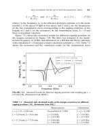
Figure 6-13 TCP sequencing and acknowledgment.
There is another simple way of determining how much data TCP is carrying
in a segment. Simply look at the packet summary. In Frame 12, the analyzer
shows the amount of TCP data with the L=1460 notation. The two 1,460-byte
segments of data sent in Frames 12 and 13 equal 2,920 bytes. In Frame 14, you
see host BRUCE sending an acknowledgment. You know by the value of the
acknowledgment field that BRUCE has acknowledged all bytes sent to it by
host ROLLINS. If you take the original sequence number sent by ROLLINS in
Frame 12 and add 2,920 bytes to it, you get an acknowledgment number of
1147164. TCP acknowledgments indicate to the host receiving the acknowl-
edgment that the host has received all bytes up to but not including the
sequence number contained in the acknowledgment field. Another way to put
this is that the acknowledging host expects the sending host to use that
sequence number next in its transmissions.
Look at Frame 15. What sequence number does host ROLLINS use? If you
guessed 1147164, you were right. Look at the next two segments sent by
ROLLINS in Frames 15 and 16. They also are 1460 bytes each for a total of
2,920 bytes of data over two packets. Their acknowledgment by host BRUCE
indicates that BRUCE received both segments and expects the next TCP seg-
ment to have a sequence number of 1150084. Next, two more segments of
2920 bytes sent
2920 bytes acknowledged
Transmission Control Protocol 201
09 429759 Ch06.qxd 6/26/03 8:58 AM Page 201
1460 bytes are each acknowledged by BRUCE with an acknowledgment num-
ber of 1153004. Next, another 2,920 bytes sent by ROLLINS in Frames 21 and
22 are acknowledged by BRUCE with an acknowledgment number of
1155924. I think you get the picture now.
TCP Retransmissions
The previous example shows what happens when a TCP data transfer is occur-
ring normally. Many times though a data transfer does not occur normally.
Being a reliable transport protocol, TCP has the ability to handle situations in
which data does not flow over the network in a neat and orderly fashion, as
was the case in the previous example. Sometimes data gets lost. When this
occurs TCP will retransmit the data. I want to take a look at an example of how
TCP does this. In Figure 6-14, you see what happens when a host with an exist-
ing TCP session is unable to deliver data to another host.
Frame 1 is a data transmission during an active TCP session. You know that
the session is active because the ACK bit is set. The sequence number of the cur-
rently transmitted byte is 2195533. You would expect DORIA to acknowl-
edge this data with an ACK number of 2195548 because ANDREA is sending
15 bytes of data. Instead, in Frame 2 you see ANDREA sending another TCP
segment with the same sequence number. In fact, this occurs four more times,
in Frames 3, 4, 5, and 6. These are what are known as TCP retransmissions.
Retransmission Time-Out
When TCP sends a segment of data to a host, it will wait a set period of time
called the retransmission time-out (RTO). If it does not receive an acknowl-
edgment from the host during that time, it will retransmit the data segment.
Implementations vary as to how long they will wait before retransmitting a
data segment. Most implementations determine the RTO by something called
the smooth round-trip time (SRTT). The speed at which acknowledgments are
returned by a host determines the SRTT upon which the RTO is based. The
faster acknowledgments are returned, the lower the RTO, and vice versa. If a
TCP acknowledgment is not received in roughly double the SRTT, TCP will
retransmit the segment. In Figure 6-14, you can see that TCP makes five
attempts to retransmit the data. With each retransmission, TCP will double the
time it waits before sending the next retransmission. Look at the delta time;
notice that the retransmissions occur at 373ms, 871ms, 1.72sec, 3.53sec, and
7.12ms. The retransmission intervals are not exact, but they are roughly dou-
bled each time. This rough interval is due to how the TCP/IP stack uses a com-
puter clock interval to tell time. After five unsuccessful attempts to retransmit
a data segment, TCP informs the application that it was unable to deliver the
data. Depending on the application, it may decide to keep trying or disconnect
the session.
202 Chapter 6
09 429759 Ch06.qxd 6/26/03 8:58 AM Page 202
Figure 6-14 TCP retransmissions.
Case Study: Bad RTO
Figure 6-15 shows what happens when a host calculates the retransmission time-
out incorrectly. In Frame 6, you see the expert system complaining about a Fast
Retransmission by host Printer. Using Wildpacket’s Set Relative Packet fea-
ture, I was able to, at Frame 4, reset the relative time to zero and let it count
upward. Why Frame 4? Because that is the original TCP segment that was
retransmitted in Frame 6. The TCP sequence number in Frame 4 is 2589; you can
see that this sequence number is also contained in Frame 6. Furthermore, both
packets are transmitting the same amount of data, 1 byte. The analyzer flags this
as a fast retransmission because it is within the threshold set by the analyzer.
How do you know that the analyzer is correct? Previously I discussed how
the RTO is based on how fast acknowledgments are returned by a host (the
SRTT). Look at the delta time in Frame 3. This tells you that the Server
acknowledged the Printer’s SYN segment in 44 milliseconds (0.044288).
This is the first and only SRTT calculation performed by the printer. The Rel-
ative Time in Frame 6 is the RTO being used by the server. The server
waited only 3 milliseconds (0.003362) before retransmitting the segment it
sent in Frame 4. Considering its first SRTT measurement of 44 milliseconds, a
3 millisecond RTO is much too fast.
Transmission Control Protocol 203
09 429759 Ch06.qxd 6/26/03 8:58 AM Page 203
Figure 6-15 Fast retransmission.
Fast retransmissions are not particularly harmful, but they do waste band-
width, especially on low-speed WAN links. Usually, it is best to let a host cal-
culate its own RTO because most hosts actually do it correctly. In this case,
however, it might be valuable to hard-set the RTO timer to a higher value. Of
course, contacting the vendor for a resolution is always on option also.
NOTE Fast Retransmit is actually an algorithm specified in RFC 2001. When a
host has not received an acknowledgment for a lost segment and receives three
acknowledgments in a row with the same acknowledgment number, it will
retransmit the lost segment before the the retransmit timer expires.
Delayed Acknowledgments
TCP does not always acknowledge data immediately upon receiving it.
Because TCP is a full-duplex protocol, you almost always have data traveling
both ways, even on a largely one-way transaction. During a file read operation,
most of the data will be coming from a server towards a client. But there is
almost always some upper protocol control information that needs to be sent
back to the client every so often. It is to TCP’s advantage to send this data at
the same time it is acknowledging data it has received from a host. This is
called the piggyback ACK.
For example, assume that Host A has sent Host B a file open request. Host B
is going to have to send a reply back to Host A indicating that the file is open.
Host B is also going to have to acknowledge Host A’s TCP segment containing
the file open request. By combining the upper-layer reply with the TCP
acknowledgment, TCP can do in one packet what would otherwise take two.
Figure 6-16 illustrates how this works. Instead of immediately sending an
acknowledgment, TCP waits to see if there might be any data from the appli-
cation that could be sent in the direction of the acknowledgment. If TCP sends
Printer retransmits TCP segment 2589 (frame 4) at 3.3ms in Frame 6
SRTT calculation based on 44ms RTT
204 Chapter 6
09 429759 Ch06.qxd 6/26/03 8:58 AM Page 204
Figure 6-16 Delayed acknowledgment.
192.168.1.100
192.168.1.100
192.168.1.15
192.168.1.15
SEQ=100 ACK=501 Length=100 WIN=8760 (File Open Request)
SEQ=802 ACK=200 ACK Length=0 WIN=8760 (TCP Acknowledgment)
SEQ=802 ACK=602 Length=54 WIN=8760 (File Open Response)
SEQ=802 ACK=200 ACK Length=54 WIN=8760 (File Open Response)
SEQ=100 ACK=501 ACK Length=100 WIN=8760 (File Open Request)
No Delayed ACK
Delayed ACK
Transmission Control Protocol 205
09 429759 Ch06.qxd 6/26/03 8:58 AM Page 205
an immediate acknowledgment, it will end up having to send another packet
containing the host’s data. Delayed acknowledgment saves bandwidth by
reducing the amount of packets it takes to acknowledge a segment of data.
Case Study: Slow Surfing
Delay in a transaction can take on many forms. The key to pinpointing where
the delay is coming from is to understand the transactions involved in the delay.
Take Web surfing, for instance. All transactions are initiated by the client. A
server does not initiate any traffic; it simply waits for the client to request Web
pages, graphics, and other documents, which it serves up using HTTP. In this
case study analysis, a group of users were experiencing very slow Web
response times on the Internet and even to some sites internally. There were
multiple routers and switches between their segment and the Internet seg-
ment, and their browsers were configured with auto-proxy configuration files
to provide redundancy.
I took an analyzer to their segment and captured several sessions of users
surfing during the normal workday. When you are analyzing delays, it is
important to view traffic as a series of transactions. The process of viewing a
Web page is really just a series of small transactions. I discuss HTTP more in
the next chapter, but for now it’s important for understanding this case study
to know that Web pages are just a series of objects or elements. Your browser
downloads each object such as a graphic file in a separate TCP session. When
analyzing one particular user’s Web session, we kept seeing these delays
between object downloads. When a TCP session ended and the next one
began, I was seeing long delays, anywhere between 2 to 8 seconds. Figure 6-17
illustrates what I saw on the analyzer.
Figure 6-17 Browser latency.
206 Chapter 6
09 429759 Ch06.qxd 6/26/03 8:58 AM Page 206
NOTE Newer Web browsers support a technique called pipelining whereby
the browser can request multiple objects using a single TCP connection.
Between Frames 43 and 48, you can see the browser finishing the down-
loading of a Web object and disconnecting that TCP session. After 2.5 seconds,
the browser opens another TCP connection to start the downloading of the
next Web object. From the receipt of Frame 48 until the browser initiates the
next TCP connection, the host waits 2.5 seconds. If a Web page contains 20
graphics files as well as links, pictures, and other elements, a 2.5 second delay
between each object’s downloading could cause the entire process to take min-
utes to complete.
Besides the 2.5-second wait between the close of the old session and the
establishment of the new one, I noticed that the browser was also using a new
proxy server. Why? What I discovered was that every time the host would
open a new element, it would consult an auto-proxy.pac file to find out what
proxy server it should use. Auto-proxy.pac files are configuration files that
contain a small bit of code to randomize which proxy server is used during
each connection. This is the reason that the browser was choosing a new proxy
server on the next connection. Unfortunately, this small process was adding
seconds to each TCP connection. Once again, a call to the vendor and a soft-
ware upgrade on the client’s browser software fixed the problem.
When analyzing delays such as this one, it is important to always confirm
that the client is not waiting for any more data from a server. If you look at the
sequence number in Frame 47 where the Browser client sends the Proxy Server
a FIN for the current session, it is 47669. In Frame 48, Proxy Server A acknowl-
edges the FIN with an ACK number of 47670. This information told me that
the browser was finished with the current session and would not be receiving
any more data from it. In client/server applications, the client is always
responsible for the requesting of data from the server, not the other way
around. When the server has no more data to send the client, any delays at that
point are always due to the client.
The Push Flag
When an application using UDP passes data down to the transport layer, UDP
will immediately pass the data down to the network layer for transmission
onto the network. When a host receives UDP data, it will immediately pass the
data up to the application. There is no wait, no reassembly of data, and no
bundling of acknowledgments with outgoing data as there is in TCP. When
TCP receives data from a peer TCP stack, it does not always pass the data up
to the application. TCP will sometimes wait to see if more data is sent to it so
that it may acknowledge more data with a single ACK. This process converses
bandwidth.
Transmission Control Protocol 207
09 429759 Ch06.qxd 6/26/03 8:58 AM Page 207
However, sometimes this delay can affect an application, for example, a Tel-
net session where quick screen updates are critical to the functioning of the
application. If an application needs a receiving host’s TCP stack to immedi-
ately pass data up to the application without delay, it sets the Push (PSH) flag
(also known as the Push bit). When TCP receives data segments with the PSH
flag set, it will not wait to see if other data is on the way. It will immediately
pass the data to the upper-layer application or protocol. You may also see the
Push flag set on the last segment of a large data transfer.
In Figure 6-18, you can see a host whose browser has aborted an HTTP ses-
sion by sending TCP Reset segments to the Web Server. Starting in Frame 314,
the browser aborts the connection and sends a Reset every time the Web server
attempts to deliver it more data. This example really shows the robustness
of the TCP protocol. The Web server continues to send the data in its buffers to
the client. On the last TCP segment it sends, it sets the PSH bit to notify the
receiving application that it should pass any data waiting in its buffers to
the application. Setting the PSH bit is very common when a server is sending
the last segment of data to a client, even more so when it hasn’t received an
acknowledgment from the client for any of its sent data. Setting the PSH bit is
almost like a last-ditch effort to tell the client to please process the previous
data it has sent. Unfortunately, in this case, the receiving application hung and
most likely never saw any of that data.
Figure 6-18 Push bit.
208 Chapter 6
09 429759 Ch06.qxd 6/26/03 8:58 AM Page 208
TCP Sliding Windows
TCP has another method of buffer control called the TCP window. If you’ve
been wondering what all of those W=8760 statements in the summary panes of
the examples were, you’re going to find out now. TCP allocates a finite num-
ber of buffers for receiving data from a peer TCP host. The TCP Window field
lets TCP inform the peer TCP host how much buffer space it has to receive
data. The W=8760s are the decodings of the value in the Window field.
At the beginning of a TCP connection, both hosts will announce their
window size in the SYN segments they send to each other. As data flow pro-
gresses, the hosts will inform each other of how much buffer space they have
left to accept data. Hence, the TCP window slides back and forth as it adjusts
itself to how much buffer space is left.
NOTE A complete understanding of the TCP window is unnecessary in most
troubleshooting situations. For those interested in the semantics, I would refer
you to W. Richard Stevens’ TCP/IP Illustrated, Volume 1, which I’ve mentioned
before, or J. Scott Haugdahl’s Network Analysis and Troubleshooting (Addison-
Wesley, January 2000). Both offer excellent descriptions of the TCP sliding
window operation.
The TCP Window’s main purpose is flow control between sender and
receiver. The best way to think of the TCP Window is to think of it as a physi-
cal window. When a window is open, it lets more air in; when it’s closed, it
allows less air in. Thinking of data as air is a great way to view how the TCP
window operates. Bigger window, more data; smaller window, less data. The
amount of data that will pass through the window is called the window size.
Three things affect the TCP Window size:
■■ One is the rate at which TCP is receiving data. A fast sender can easily
overwhelm the TCP buffers of a slower receiver. In that case, the receiv-
ing station’s TCP stack should reduce the window size, informing the
sender it cannot accept more data.
■■ Second is the speed at which an application processes the data inside
of TCP’s buffers. Just because TCP has received data does not mean that
the application has processed it. A slow application could easily cause
TCP’s buffers to fill up quickly.
■■ The third thing that can affect the TCP window is the amount of TCP
buffers available on the receiver. The lower the amount of buffers, the
lower the window size. Often very small PDA-type network devices do
not have the memory that a larger desktop-based system would have.
To conserve memory then, they may have a lower amount of TCP
buffers available to them.
Transmission Control Protocol 209
09 429759 Ch06.qxd 6/26/03 8:58 AM Page 209
Figure 6-19 TCP window operation.
Now, take a look at an example of how the TCP Window operates. In Fig-
ure 6-19, you can see an FTP session start up in Frame 4. Both the FTP client and
server advertise their TCP windows, 17520 and 57344 bytes, respectively.
Frame 8 starts the data transfer from the server to the client. In the next 34
frames, the server continues to send FTP data to the client. The acknowledg-
ments in Frames 10, 13, 17, and 22 all contain the same original window size
advertisement of 17520.
However, the situation changes in Frame 28. In Frame 28, the client is telling
the FTP server that now it can accept only 10220 bytes of data. Also, notice
that in the same packet the client has acknowledged, so far, all data that the
server has sent to it. Once again, you can tell by the acknowledgment number
in the frame. The ACK number of 510933901 indicates that all bytes up to, but
not including, 510933901 have been received and that the client expects the
next TCP sequence number to be 510933901. In Frames 29 to 34, the FTP server
sends the client 8760 more bytes of data. (The six packets of 1,460 bytes each
equal 8,760 total bytes of data sent.) Then in Frame 35 you can see something
very interesting. The client has drastically reduced its window size, now
advertising only 1460 bytes of data. This means that the FTP server is permit-
ted to send only one more full-sized TCP segment of 1,460 bytes before the
receiver’s buffers become filled. Why the sudden drop in window size?
Consider the three reasons for the adjustment in window size I just outlined.
It’s doubtful that the receiving station has a minimal amount of buffer space
because it started out with 17,520 bytes of buffer. With that eliminated, the
210 Chapter 6
09 429759 Ch06.qxd 6/26/03 8:58 AM Page 210
problem could be one of two things, that the sender is sending data too rapidly or
that the application is not processing the data in the TCP buffers quickly enough.
Let’s go on to the next sequence of frames to find out. In Frame 36 of Figure
6-20, you can see that the FTP server did, in fact, send only one more full-sized
segment of 1460 bytes to the client.
In Frame 37, the client acknowledges that segment and updates its window
size back to 17520 bytes. The reduction in window size was due to the time it
took the FTP client to process the data in its buffers. Sudden changes in a host’s
window size advertisements are indicative of this behavior. The server is now
allowed to send the client 17,520 bytes of data. In Frames 38 to 45, the server
sends 11680 bytes of data to the client. Now, look closely and you can really see
how TCP operates. In Frame 46, the client acknowledges the TCP data sent to it.
But this time it does not acknowledge all of the data. The acknowledgment num-
ber it sends back to the server is 510949961, indicating to the server that the
client has received 5,840 more bytes of data. Its acknowledgment number
acknowledges only bytes 510944121 through 510949960 as having been received.
Doing some math will help you here. If the original window advertisement was
17,520 bytes and the server sent 11,680 bytes of data, the server can send only 5,840
more bytes of data before exceeding the window size advertised by the client.
However, in Frame 46 the client acknowledges 5,840 of those 11,680 bytes. So, now
the window slides open 5,840 more bytes for an advertisement of 11680 bytes.
Figure 6-20 TCP window operation continued.
Transmission Control Protocol 211
09 429759 Ch06.qxd 6/26/03 8:58 AM Page 211
TCP’s sliding window mechanism is not easy to understand, but with prac-
tice you can master it. It is critical to understand it when troubleshooting
performance problems between hosts. Watching how fast a host acknowledges
data it receives gives you a good idea of its processing power and, further, how
efficient an application is at processing received data. You will not always see
the same types of results every time you analyze a TCP data transfer. I recom-
mend analyzing data transfers between different kinds of hosts over different
networks, with different applications. All three or any combination of the three
will usually yield different results. The important thing to do is to establish a
baseline as to how a host processes data during normal operation. This base-
line gives you a reference to use in the future if problems arise.
Slow Start and Congestion Avoidance
There is actually another type of window that exists in TCP that you don’t see
explicitly advertised in the packets. It is called the congestion window. The
congestion window exists because of something called TCP Slow Start.
In Figure 6-19, the FTP client immediately advertises 17520 bytes of data in
its window size. You’ll notice in that example, though, that the FTP server does
not immediately send 17,520 bytes of data; it sends only 1,460 bytes of data.
The reason it does this is because of something called Slow Start. Slow Start is
a congestion avoidance algorithm implemented in TCP stacks to avoid unnec-
essary packet loss. Instead of sending out the exact amount of data advertised
in the receiver’s window, the sender starts out sending one segment at a time
and then doubles the amount of data it sends each time. It uses something
called the congestion window to determine how much data to send out each
time. Initially, the congestion window equals 1 for one segment; it then dou-
bles each time until the receiving host stops sending timely acknowledgments
to its data. Figure 6-21 illustrates Slow Start.
Figure 6-21 Slow Start in action.
Congestion Window = 1
Congestion Window = 2
Congestion Window = 3
Congestion Window = 4
Congestion Window = 5
Congestion Window = 6
212 Chapter 6
09 429759 Ch06.qxd 6/26/03 8:58 AM Page 212
Figure 6-22 Reduced congestion window.
Even though the receiving window is 17520, the sender’s congestion
window is initialized at one segment. You can see how upon successful trans-
mission and acknowledgments, the sender slowly increases its congestion
window and sends out more segments. The congestion window is adjusted
based on how fast acknowledgments are returned by the receiving host. In Fig-
ure 6-22, you can see that the congestion window has increased even more, up
to 8, but when only half of the data sent in the last congestion window is
acknowledged (Frame 46), the host quickly reduces the congestion window to
half of its original value.
You can also see in Figure 6-22 that in Frame 56 the FTP server has retrans-
mitted segment 510949961, which was originally sent in Frame 42. Whenever
a sender experiences a segment loss (or one that has not been ACK’d quickly
enough) it will reduce the congestion window by half, so in this example the
congestion window is cut from 4 to 2. After all data has been successful
received, you can see it starting to increase the congestion window again to 3.
The TCP window and the congestion window constantly change during the
lifetime of a connection, which allows a host to send the optimal amount of data
based on network conditions and the ability of the host to receive that data.
Nagle Algorithm
Some applications, by their nature, transmit very small amounts of data. Some-
times these data segments are considerably smaller than a receiving hosts MSS.
The Nagle Algorithm states that a host may have one only TCP segment less
than the MSS that is unacknowledged. This algorithm prevents a host from
flooding the network with very small packets. Hosts implementing the Nagle
Algorithm will buffer all small data writes from an application and send them
as one large segment. Figure 6-23 shows how the Nagle Algorithm works.
Congestion Window = 8
Congestion Window = 4
Congestion Window = 2
Congestion Window = 3
Transmission Control Protocol 213
09 429759 Ch06.qxd 6/26/03 8:58 AM Page 213
Figure 6-23 Nagle Algorithm in action.
From my host STEVEO, I Telnetted to a Unix server FQC Server. While cap-
turing a Telnet session, I held the n key down for several seconds to force our
host to send out multiple n characters. Instead of sending one character per
packet, you can see that in Frames 215, 223, 231, and 239 the TCP stack is
bundling the data and sending it as a single larger packet. This saves band-
width because you don’t have one packet per character being sent across the
network.
NOTE Some applications need to disable the Nagle Algorithm because it is
critical that destination hosts receive the data without any delay. XWindows is one
of those applications. Another is an application called Virtual Network Computing,
which functions similar to XWindows, and applications like PCAnywhere that
allow a user to control the mouse and keyboard of another computer.
In Figure 6-24, I established a VNC session between two computers. Both
computers negotiated their MSS to be 1460 bytes. Once the VNC session was
established, I moved the mouse around constantly for about 20 seconds. This
forced the VNC host to have to update my local VNC application constantly
with mouse movement and position data. You can see in the trace that the host
machine has disabled the Nagle Algorithm for the connection. You can see it
sending out more than one small segment of data that is not acknowledged.
Although you may never run into a situation where understanding the
Nagle Algorithm is necessary, it is important to understand its existence and
why it is enabled or disabled. Unless an application disables the Nagle Algo-
rithm, it is active by default on almost all TCP/IP stacks.
214 Chapter 6
09 429759 Ch06.qxd 6/26/03 8:58 AM Page 214
Figure 6-24 Nagle Algorithm disabled.
Data Protection
The TCP protocol guarantees data integrity by the implementation of a check-
sum. The checksum is calculated over the entire contents on the TCP data. Just
as with UDP’s checksum, if the checksum value the receiving host calculates is
different from the value in the checksum field, the data segment is discarded.
A valid checksum guarantees that the receiving host’s application is getting
exactly the same data the source host sent it. If for some reason a packet is
received with a correct data link layer CRC and an incorrect TCP checksum,
the chances are that the packet’s data was corrupted somewhere between
Layers 2 and 4, either that or (in one case I have seen) the sending host was
actually miscalculating the TCP checksum.
Case Study: TCP Checksum Errors
While analyzing a connection time-out issue between two groups of
geographically dispersed users on a LAN, I employed the use of RMON
probes to perform data captures.
TIP RMON probes are generally not good analyzers, but in this case the
problem was so difficult to capture that I used the RMON probes to capture
and store large volumes of traffic data until I could, at a later time, download
the traffic into capture files for analysis.
The RMON probe used a proprietary trace file format that the analyzers
were unable to read. Fortunately, the probe management software had a con-
versation utility so that I was able to convert the traces into Sniffer enc format,
4 small segments
less than the MSS
All data acknowledged
Transmission Control Protocol 215
09 429759 Ch06.qxd 6/26/03 8:58 AM Page 215
which my analyzer could read. Upon analyzing the capture, I noticed numer-
ous TCP checksum errors. Figure 6-25 illustrates the tracefile.
To an untrained analyst, it may appear as though the resolution I was seek-
ing to this problem had to do with the TCP checksum errors. After all, the
expert mode was telling me that there was a problem. After careful examina-
tion of the packets, I realized that the checksum errors were not errors at all
and that the packets were good.
How did I know this? It comes from having an understanding of the proto-
cols. When TCP receives a segment with an incorrect TCP checksum, it
discards the segment. Take Frame 201, for instance, being sent by host CHRIS.
If this frame actually contained an invalid checksum, the host’s receiving TCP
stack would never have acknowledged the data. In Frame 205, host CHRISSY
acknowledges the 1078 bytes of data sent by host CHRIS in Frame 201. The
data is being acknowledged and passed on to upper layers, which means that
the packets are good.
But why the TCP checksum symptoms then? Was the analyzer wrong? No,
in fact, the analyzer was right; the checksum values in the fields are incorrect.
What was happening was that the conversation program I was using to con-
vert the trace files into Sniffer format was periodically corrupting the values in
the TCP Checksum field. The receiving host was not receiving incorrect check-
sum values, but in the traces they were incorrect.
Figure 6-25 TCP checksum errors.
216 Chapter 6
09 429759 Ch06.qxd 6/26/03 8:58 AM Page 216
This is a fine example of how an analyzer’s expert mode can lead you
astray as to the true source of the problem. When you see TCP checksum
errors, data should not be passing. In this example, when I matched up the
sequence and acknowledgment numbers, I could see that the host was
acknowledging frames that the analyzer said were corrupt. However, if they
were truly corrupt, the host would have discarded them, not sent an acknowl-
edgment. Never blindly trust your tools; always base your analysis on your
knowledge of the protocol’s operation.
TCP Expert Symptoms
The TCP protocol is probably responsible for more misdiagnosis of protocol ana-
lyzer symptoms than any other protocol. The reason is that it is so dynamic. The
functions built into TCP have made it a fantastic protocol capable of tuning itself
to meet the needs of almost any network or network condition. It is also the rea-
son that analyzers’ expert modes seem to constantly notify you of every small
symptom relating to a TCP data transfer. There are two categories of TCP expert
symptoms.
■■ One category you should pay attention to. I call these symptoms to
watch for:
■■ TCP Transport Retransmissions
■■ TCP Reset Connection
■■ TCP Repeated Connection Attempt
■■ TCP Low Starting MSS
■■ TCP Invalid Checksum
■■ TCP Connection Refused
■■ TCP Lost Connection
This first group of symptoms deals primarily with whether something
is working or not working. Lost Connection, Reset Connection, Repeated
Connection Attempt, and Connection Refused all indicate something
wrong with the TCP connection. Invalid Checksum and Retransmission
symptoms affect a session because they indicate that packets are going to
be dropped or are already being dropped. Repeated connection attempts
are a type of retransmission that occurs during the establishment phase
of the connection. The Low Starting MSS symptom is important in that
you may be able to increase performance by simply changing a variable
on a host.
■■ The other category of symptoms you should take note of but not let
concern you greatly. I call this category symptoms to take note of:
■■ TCP Zero Window
■■ TCP Stuck Window
Transmission Control Protocol 217
09 429759 Ch06.qxd 6/26/03 8:58 AM Page 217
■■ TCP Low Window
■■ TCP Idle Too Long
■■ TCP Long ACK
The second group of symptoms deals with how TCP is transferring
data. These are the most confusing symptoms to an untrained analyst.
None of the symptoms in and of themselves indicates that anything is
horribly wrong. These symptoms could be showing up because of how
a TCP stack does (or does not) implement certain TCP functions such as
window sizing or delayed acknowledgments.
WARNING Expert symptoms are fantastic flags to let you know that
something might be wrong. However, they should never be taken at face value
as indicating that there is a problem on the network. A general rule about
analyzer expert symptoms is that if you see a symptom, you should be able to
understand why the analyzer is giving you the symptom. No matter how good
an expert symptom is, never blindly trust it without first verifying the reasons
behind the symptom.
TCP Application Analysis
There are numerous applications that utilize the TCP protocol. It is imperative
to have an understanding of how TCP performs its functions independently
from the responsibility of the application. In this section, I take a look at some
examples of analyzing application-specific attributes of TCP data transfers. In
this section, I review what I have discussed in the previous sections on the TCP
protocol and its operations with respect to how applications and TCP integrate
to maximize performance and overcome latency.
TCP and Throughput
There are three things that determine the throughput of an application:
■■ Segment size
■■ Latency
■■ Window size
Segment Size
Having each host use a maximum segment size that is as large as possible helps
eliminate inefficiency due to sending multiple small segments over the wire.
218 Chapter 6
09 429759 Ch06.qxd 6/26/03 8:58 AM Page 218
Since each small segment incurs the same amount of overhead from the data
link, network, and transport protocol headers, it is much more efficient to trans-
fer those multiple small segments as one large segment across the network.
For example, take a host that uses the default TCP segment size of 536 bytes.
The overhead of the lower-layer protocols is going to be 58 bytes, bringing the
total packet size to 594 bytes. At 536 bytes of data, the overhead contributes 9.7
percent of data to the entire frame. However, if you increase the segment size
to 1,460 bytes (on Ethernet), the percentage of overhead drops to 3.9 percent of
the total frame size. While a 5.8 percent reduction of data might not seem like
a lot, remember that each 536 bytes of data is going to need a separate packet
in order to be transmitted. A maximum segment size of 1,460 bytes can be sent
in one packet. The same 1,460 bytes would need three packets in order to be
transmitted across the network and incur an extra added overhead of 12 per-
cent. During a large file transfer, that 12 percent can add up quite quickly and
inhibit performance over lower-bandwidth WAN links.
CROSS-REFERENCE Overhead and packet efficiencies are discussed in
more detail in Chapter 5.
Latency
Latency is the total amount of delay between a sender sending data and a
receiver receiving it. TCP helps overcome latency. A good analogy is grocery
shopping. Say you live 3 miles away from the local grocery store. Between you
and the store is a highway with a speed limit of 60 mph. Traffic is normally
light, so you are able to travel at the maximum speed limit to reach the store in
3 minutes. While you are there you buy a single item, for example, milk. You
then get in your car and travel 60 mph home again in 3 minutes. You drop off
the milk, get in the car, drive 60 mph to the store in 3 minutes. While you are
there, you buy eggs. After purchasing the eggs, you get in the car and drive
home, arriving there in 3 minutes. Assume that you have 10 items to buy.
Using this technique, it would take you at least 60 minutes to get home with all
10 items (10 items × 6-minute round trip per item = 60 minutes). Wouldn’t it be
to your advantage to buy all 10 items at once and make one single round trip
to the store? If you did so, you would dramatically reduce the time it would
take you to shop. Although this seems to be a ridiculous example in real life, it
is a very realistic example of how some applications operate over TCP. Instead
of handing TCP multiple blocks of data to transmit all at once, they send small
amounts of data back and forth across the network. The Nagle Algorithm (dis-
cussed earlier in the chapter) was specifically designed to prevent applications
from doing this by forbidding them to have more than one outstanding small-
sized segment on the network at a time.
Latency can also occur on other places besides the network. In Network Analy-
sis and Troubleshooting, Haugdahl refers to the kinds of latency transactions you
Transmission Control Protocol 219
09 429759 Ch06.qxd 6/26/03 8:58 AM Page 219
may face in what he calls the “latency wedge.” He views the three basic parts
of a transaction—request, processing, and reply—as making up a triangular
wedge-shaped object.
■■ Request. Latency can occur on a client when it doesn’t request data
quickly enough.
■■ Processing. Processing delay takes place once a packet reaches a host. It
must be processed by all layers of the OSI model before being handed off
to the application. (Later in this section, I present an example that shows
you how to determine the status of a TCP segment once it is inside a host.)
■■ Reply. A server application may not respond to a request in a timely
fashion.
Window Size
TCP window sizes allow hosts to give each other feedback concerning the
amount of buffers they posses to accept TCP data. The TCP sliding window
keeps data flowing at the fastest possible rate by constantly informing the
sender of how much data it can accept. The congestion window makes sure
that the network or the destination host is not overwhelmed by data too
quickly. Along with data acknowledgments, both windows work in harmony
to provide the best possible performance.
Figure 6-26 HTTP delay.
220 Chapter 6
09 429759 Ch06.qxd 6/26/03 8:58 AM Page 220
As I present the following case studies, keep in mind the three factors that
affect throughput. Their understanding is critical when diagnosing the reasons
behind poor throughput.
Case Study: Slow Web Server
This first example illustrates how to discern delay inside of a host.
In this case, user complaints as to how long it took to load a Web page led my
team to analyze the transactions during the HTML page loading process. After
watching the client browser (JAY) download the entire page, we concentrated on
each individual TCP session to determine which session was causing the delay.
Figure 6-26 shows a filtered-down trace with the session causing the problem.
You can see the TCP session start normally with SYNs and ACKs being
exchanged. In Frame 4, you can see the client send a request to open an Active
Server Page. In Frame 6, you can see it takes exactly 7.331 seconds for the
server to send back the first of several HTTP data segments. So, how do you
know if the problem is with the network or the application? After all, if the net-
work connection had gone down in the time between Frames 5 and 6, the
HTTP reply in Frame 6 could have been the last retransmission attempt by the
server that just happened to make it through. The TCP acknowledgment
segment in Frame 5 gives you a clue. Figure 6-27 shows a decode for Frame 4.
In Frame 4, the client (JAY) is making an HTTP request to server BOB to
open an Active Server Page (asp) file. The TCP sequence number sent along
with this request is 2490181104. The HTTP request data is 440 bytes in length
(IP Length of 480 – 40 for IP, TCP headers = 440). In Frame 5 you see that 126
milliseconds later the server sends a TCP acknowledgment for that data. You
know that the server is acknowledging the 440 bytes of client data because it
sends an acknowledgment number of 2490181544. This tells you two things:
■■ The network round-trip time is 126 milliseconds or less. If server BOB’s
TCP stack can return an acknowledgment in 126 milliseconds, you
know that the network is capable of delivering the data in that time.
■■ The TCP stack on the server has received the request and has notified
the application that it has data waiting to be processed.
The rest of the 7.331 seconds it took to turn around the HTTP request is the
result of application delay. TCP has done its job, acknowledging the data in
126 milliseconds; the only other job left is for the application to process it.
Figure 6-28 shows a more simplistic view of this process.
NOTE The 126 millisecond time for TCP to acknowledge the data segment
includes the TCP Delayed Ack time for TCP to wait and see if it can piggyback
its acknowledgment onto some data being sent back to the client.
Transmission Control Protocol 221
09 429759 Ch06.qxd 6/26/03 8:58 AM Page 221
Figure 6-27 Fast ACK, slow application.
Case Study: Bad Windowing
When TCP transfers and acknowledges data it should do so in a fashion that
enables a smooth constant flow of data. A good TCP stack will exhibit very few
windowing symptoms such as Stuck Windows or Zero Windows messages in
an analyzer. A good stack will use its window advertisements effectively to
avoid the need for a receiving host to stop the data transfer all together until it
catches up. Figure 6-29 shows one such TCP stack that didn’t use any window
advertisements.
The receiving host began with an advertised window of 17520 bytes and
left it at the same value during the life of the data transfer. By not using win-
dow advertisements, a receiving host has no other choice but to not acknowl-
edge data in a timely fashion. Normally, a host will inform a sender that its
window has been reduced. This causes the sender to adjust the number of data
bytes it is currently sending out. Without this feedback, a sending host will
keep sending the full window size of data every single time. Notice in Frame
14 that the receiving host starts acknowledging, frame by frame, all the pre-
ceding data sent to it. It would have been much more efficient to wait and
acknowledge all of the data with a single TCP acknowledgment rather than
waste network bandwidth on individual ACKs.
222 Chapter 6
09 429759 Ch06.qxd 6/26/03 8:58 AM Page 222
Figure 6-28 TCP and application processing.
JAY
Request (Frame 4)
HTTP
TCP
IP
Ethernet
Browser
BOB
HTTP
TCP
IP
Ethernet
Web Server
Application Response (Frame 6)
TCP Acknowledges Request (Frame 5)
7 sec
126ms
Transmission Control Protocol 223
09 429759 Ch06.qxd 6/26/03 8:58 AM Page 223
Figure 6-29 Bad window adjustment.
Case Study: Inefficient Applications
A lot of applications are written by people who have no concept of how TCP
works. These network “unaware” applications tend to transfer very small
amounts of data back and forth across the network. When analyzing an applica-
tion that runs over TCP, it is important to take into account the maximum seg-
ment size being used and also the window advertisements sent by each client.
This information will give you a very good idea of what hosts on each end of the
connection are capable of. If you see packets that are smaller than the MSS being
sent back and forth, you can bet that the application is not using TCP effectively.
In the early days of SQL applications, almost all of them exhibited this same
behavior, which led to countless problems when these databases were trans-
ferred from terminal-based mainframe platforms to client/server-based archi-
tectures over wide area networks. Instead of just receiving screen updates,
the client applications were receiving the actual data over the network. All of
those small segments making their way back and forth across low-speed WAN
circuits caused innumerable delays and increased application latency, some-
times to the point of the application simply not functioning. It is critical to
understand how an application works with respect to the data sizes and send-
to-receive ratios it uses between clients and servers.
224 Chapter 6
09 429759 Ch06.qxd 6/26/03 8:58 AM Page 224
High-Performance Extensions to TCP
From its inception, TCP has not changed very much. Besides some modifica-
tions to behind-the-scenes algorithms, the basic format and function of the
protocol has been the same for the last 10 years. The designers of the protocol
left room for improvements and changes. The TCP Options field is one aspect
that has enabled newer TCP functions to be implemented, while still provid-
ing for backward compatibility with older TCP stacks. In this section, I want to
take a look at these new options.
Selective Acknowledgments
TCP is a byte-acknowledged transport protocol. As you have seen in previous
sections, a receiving host acknowledges each byte of TCP data it has received.
It does so with an acknowledgment number. TCP acknowledgments may
acknowledge a single segment of data or multiple segments of data. The abil-
ity to acknowledge multiple segments of data with a single packet allows TCP
to conserve bandwidth and avoid ping-pong type protocol actions. However,
the acknowledgment scheme used by TCP also has limitations in certain situ-
ations that could actually cause more data to be sent than necessary when a
packet is lost on the network. Figure 6-30 illustrates why.
Host JAY is in the process of transmitting 2500 bytes of application data.
JAY has just sent five TCP segments of 500 bytes each to host BOB. Due to a
network anomaly, the packet containing bytes 8,000–8,499 has been lost. Because
TCP is able to acknowledge data only from a byte perspective, it has no choice
but to send an acknowledgment for bytes up to and including 7999. Even
though it has received the last two packets, containing bytes 8,500–9,999 it has
no way of informing host JAY of this. Host JAY, upon receiving the acknowl-
edgment, believes that BOB has received only the first two segments. Based on
the acknowledgment number from BOB, host JAY will retransmit all bytes
starting with 8000. As you can see in the figure, this process wastes band-
width due to the sending of two extra segments that have already been
received by the destination.
Enter the Selective Acknowledgment, or SACK, option. SACK allows TCP
to inform a host that it has received a range of bytes and that the host should
retransmit only the lost segment. Figure 6-31 illustrates how this works. Host
BOB, upon receiving all data segments except 8,000–8,500, sends an acknowl-
edgment packet with the TCP SACK option. The SACK option contains two
extra fields called the Left Edge Block and the Right Edge Block. The acknowl-
edgment field will contain the value of the last sequential segment of data
received. The SACK block fields will contain a range of bytes that the host has
also already received. In Figure 6-31 the acknowledgment number is 7999,
indicating that it has received up to and including bytes 7,000 to 7,999. The left
block field contains the value of the next byte of data that TCP has received, in
Transmission Control Protocol 225
09 429759 Ch06.qxd 6/26/03 8:58 AM Page 225