TCP/IP Analysis and Troubleshooting Toolkit phần 8 doc
Bạn đang xem bản rút gọn của tài liệu. Xem và tải ngay bản đầy đủ của tài liệu tại đây (1.42 MB, 44 trang )
HTTP Proxies
Proxy servers allow an organization to save bandwidth by funneling all Inter-
net traffic through a single (or multiple) Internet-connected host. A proxy
server gets its name by the operation it performs. Instead of an HTTP client
making requests to a Web site directly, the client sends the requests to a proxy
server that handles retrieving the Web objects on the site and returning them
to the client. Proxy servers are typically dual-homed servers containing two
NIC cards. They may or may not be running firewall software to protect an
internal network. If they are not, then the outside Internet connection is typi-
cally configured with a firewall that contains rulesets allowed access only to
and from the proxy server and the Internet. In a proxy server configuration,
inside clients have no knowledge of the outside network. All requests are sent
to the IP address of the proxy server. Proxy servers do not allow end-to-end IP
communication. On a single Web session through a proxy server, there are
actually two TCP connections:
■■ One from the client to the proxy server
■■ One from the proxy server to the Web site on the Internet
Figure 7-32 illustrates the functionality of a proxy server.
Notice how the source and destination addresses on the inside portion of
the network change as the request is sent to the proxy server. On the outside
Internet portion, the proxy server makes a TCP connection of its own to the
real Internet IP address of the Web site from its own outside IP interface.
Figure 7-32 Proxy server functionality.
ProxyServer
Internet
(Outside Network)
Inside Network
Web site
151.197.13.154
proxy (outside)
207.106.54.18
proxy (inside)
172.16.10.1
Client
172.16.10.18
TCP Session
151.197.13.154 207.106.54.18 GET / HTTP 1.1
TCP Session
172.16.10.1 172.16.10.18 GET / HTTP 1.1
Upper-Layer Protocols 289
11 429759 Ch07.qxd 6/26/03 8:58 AM Page 289
Proxy servers are actually very simple. They intercept TCP sessions and
make the request for you (proxy) on the other side of the connection. However,
they can be very difficult to troubleshoot when it comes to performance. Since
the packet’s IP addresses and MAC addresses are different on either side of the
proxy server, it is difficult to match up request and response pairs of packets
in order to measure the connection latency. Using a dual-port time synched
analyzer (Shomiti Explorer in this case), the next section shows how latency
can easily be measured.
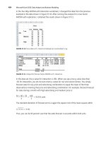
Measuring Proxy Latency
If you happen to own a dual-port analyzer that has the ability to time-sync
both interfaces to a single clock source and interweave the packets from both
interfaces, you will be able to easily measure latency on a dual-home proxy
server. You simply need to connect either side of your analyzer to both seg-
ments of the proxy server.
This connection can be made with either port mirroring or shared minihubs
on either end. Once both connections are tapped into, you can take a packet
capture while you connect to a Web site. The end result will be a mixed cap-
ture of traffic from both sides of the proxy server perfectly interweaved so that
the latency is easily seen. Figure 7-33 shows the setup and packet capture.
Figure 7-33 Measuring proxy server latency.
Proxy Server
Internet
(Outside Network)
Inside Network
Web site
proxy (outside) proxy (inside)
Dual Port Time Synched Analzyer Client
Time
start
174 ms
175 ms
2 ms
Direction
Proxy < Client
Website < Proxy
Website > Proxy
Proxy > Client
Frame
1
2
3
4
5
6
7
8
9
10
11
12
13
14
15
Delta Time
0.000.000
0.000.285
0.001.605
0.001.425
0.014.745
0.079.080
0.079.455
0.000.030
0.000.735
0.171.855
0.003.195
0.002.025
0.000.210
0.000.090
0.111.705
Rel. Time
-0:00:00.003
-0:00:00.003
-0:00:00.001
0:00:00.000
0:00:00.014
0:00:00.093
0:00:00.173
0:00:00.173
0:00:00.174
0:00:00.345
0:00:00.349
0:00:00.351
0:00:00.351
0:00:00.351
0:00:00.463
Dest. Address
Proxy (Inside)
Client (Inside)
Proxy (Inside)
Proxy (Inside)
Website (outside)
Client (Inside)
Proxy (outside)
Website (outside)
Website (outside)
Proxy (outside)
Proxy (outside)
Proxy (outside)
Website (outside)
Client (Inside)
Proxy (Inside)
Source Address
Client (Inside)
Proxy (Inside)
Client (Inside)
Client (Inside)
Proxy (outside)
Proxy (Inside)
Website (outside)
Proxy (outside)
Proxy (outside)
Website (outside)
Website (outside)
Website (outside)
Proxy (outside)
Proxy (Inside)
Client (Inside)
Summary
TCP: D=80 S=1427 SYN SEQ=52330 LEN=0 WIN=8192
TCP: D=1427 S=80 SYN ACK=52331 SEQ=351808000 LEN=0 WIN=32768
TCP: D=80 S=1427 ACK=351808001 WIN=8760
HTTP: C Port=0 GET
TCP: D=80 S=1762 SYN SEQ=351872000 LEN=0 WIN=32768
TCP: D=1427 S=80 ACK=52658 WIN=32768
TCP: D=1762 S=80 SYN ACK=351872001 SEQ=1061532264 LEN=0 WIN=32120
TCP: D=80 S=1762 ACK=1061532265 WIN=32768
HTTP: C Port=0 GET www.cnn.com
TCP: D=1762 S=80 ACK=351872266 WIN=31855
HTTP: R Port=1762 HTML Data
HTTP: R Port=1762 HTML Data
TCP: D=80 S=1762 ACK=1061535185 WIN=32768
HTTP: R Port=1427 HTML Data
TCP: D=80 S=1427 ACK=351808125 WIN=8636
290 Chapter 7
11 429759 Ch07.qxd 6/26/03 8:58 AM Page 290
In order to match up the same packets on both sides of the connection, you
have to use the application layer to identify the packets. The application layer,
HTTP in this case, gives you a clearly visible identifier to use—the GET
request.
1. In Frame 4, you can see the initial GET request from the client to the
proxy server.
2. Then in Frame 9, you see the same GET request being forwarded out of
the proxy server onto the outside connection to the Internet.
3. Next, in Frame 11, you see the first HTTP response frame coming back
from the Web site (www.cnn.com in this instance) to the proxy server.
4. Last, in Frame 14, you see the HTTP response being sent back to the
client on the inside network.
Using the relative time feature in your analyzer, you can see that after the
proxy server received the HTTP GET request that it took 174 milliseconds until
it made its own request out to the Internet. Is 174 milliseconds unreasonable?
Continue looking at the trace, and you can decide. In Frame 11, you see the
response from the Web site to the proxy server’s request, sent in Frame 9. It
took 175 milliseconds to receive a response. This includes the amount of time
it took the request to travel to and from the Web site. Strangely enough, the ini-
tial client request sat inside of the proxy server for a total of 174 milliseconds.
Considering the speed of the internal PCI bus architecture and the high-speed
processing power of a large Unix host (which the proxy server was), 174 milli-
seconds is an abysmal amount of time for the processing of a single HTTP
request.
Notice, however, that from Frame 11 to Frame 14 it took the proxy server
only 2 milliseconds to relay the Web site response back to the client. If the
proxy server could relay responses from the outside to inside interfaces in 2
milliseconds, what was happening to cause the extra 172 milliseconds of delay
going the other direction? What I found out was that the proxy server was con-
figured to track and log all outbound connection requests. Once I disabled this
feature, the delays disappeared.
Analyzing Advanced Web Architectures
Web sites have become very complex. Take, for example, the National Football
League’s Web site (www.nfl.com), which contains thousands of statistics, up
to the minute score updates, and even live streaming audio of games in action.
Today, complex Web sites do not exist as single servers but as multiple multi-
tiered systems comprised of back-end databases, application servers, and
application-aware load-balancing switches. These complex systems require
special analysis needs and techniques in order to troubleshoot and analyze.
Upper-Layer Protocols 291
11 429759 Ch07.qxd 6/26/03 8:58 AM Page 291
My first example is an architecture that utilizes the Secure Sockets Layer or
SSL. SSL is a protocol that allows application traffic between a user and a Web
server to be encrypted. Most financial sites, such as banks or e-commerce sites,
usually provide some sort of encryption in order to protect their customer’s
credit card information as it travels over the public Internet. Unfortunately,
encryption is not something Web servers do very well. When a Web server
starts performing encryption and deencryption for several hundred users, it
tends to start slowing down. The solution to this problem is to offload the
encryption process to a separate device that specializes in fast encryption at
the hardware level. Figure 7-34 illustrates architecture of this type.
The challenges in troubleshooting an architecture of this type are the multi-
ple points of analysis. In architecture such as this, it is almost better to dedicate
a multiple NIC analyzer specifically for its support.
Figure 7-35 shows another complex architecture that may exist in combina-
tion with the one shown in Figure 7-34. The architecture in Figure 7-35 is
what’s known as a three-tier application architecture. The three tiers are com-
posed of the three servers that make up the entire client/server process. It’s
easy to see how an architecture of this type poses the same problems as the
previous one. Analyzing performance problems is very challenging because,
once again, there are multiple analysis points that must be taken into consid-
eration to view the entire client/server process.
Figure 7-34 Hardware load-balancing Web architecture.
Web Server Web Server Web ServerWeb ServerWeb Server
Internet
Load Balancer
SSL Content
Accelerator
Multiple Analysis Points
292 Chapter 7
11 429759 Ch07.qxd 6/26/03 8:58 AM Page 292
Figure 7-35 Three-tier application architecture.
Unless you own an analyzer that allows you to time-sync two or more ports
to the same clock source, you are going to need to use three separate analyzers
on three separate segments to analyze performance problems in a three-tiered
architecture. Try to start capturing on each analyzer at roughly the same time.
If all servers are on the same back-end segment, use a packet such as PING to
set the relative time on each analyzer after you are done capturing. This tech-
nique will let you time-sync each analyzer within microseconds of each other
because they all will have seen the PING packet at roughly the same time.
Case Study: Web Site Failure
When analyzing a failure in an application protocol or program, I cannot stress
enough the need to analyze and troubleshoot all layers. Many times, an appar-
ent application failure is actually being caused by a problem residing in
another layer. Take Figure 7-36, for instance.
A problem with one of my favorite news sites (www.msnbc.com) actually
had nothing to do with the Web server or the site itself. The problem was with
DNS resolution. Here a DNS name server problem was inhibiting access to the
site because the IP address was not able to be resolved. In Frames 2, 4, 6, and 8,
you can see my DNS server responding with Query Status=Server
Failure messages, indicating a failure of the DNS lookup.
Application Server Database ServerWeb ServerClient
Three points of latency analysis
1
2
3
Client makes HTTP request of Web Server.
Web Server forwards data to Application Server.
Application Server makes database calls to fufill client request.
1
2
3
Upper-Layer Protocols 293
11 429759 Ch07.qxd 6/26/03 8:58 AM Page 293
Figure 7-36 Web site failure.
NOTE If you have noticed that I have sometimes mixed case studies involving
different protocols under different sections (such as this discussion of a DNS
problem in the section of the chapter on HTTP), I have. This mixture of case
studies is to stress that not all problems exist in one layer. As an analyst, you
must always take into consideration the dependent layers of an application. A
user analyzing just the HTTP protocol in this case would never have seen that
the real problem is with the session layer or DNS.
Simple Mail Transport Protocol
The second protocol most responsible for Internet growth has to be the Simple
Mail Transport Protocol (SMTP). Email has allowed millions of people around
the world to communicate. It has broken down geographical boundaries over
countries, distance, and sometimes even language. For all it does, it is actually
a very simple protocol not much different from FTP. It operates with the same
NVT ASCII character set, using simple commands and responses to transfer
email messages back and forth. SMTP specifies the use of the commands listed
in Table 7-9.
294 Chapter 7
11 429759 Ch07.qxd 6/26/03 8:58 AM Page 294
Table 7-9 SMTP Commands
COMMAND DESCRIPTION
HELO Used to identify the sender-SMTP to the receiver-SMTP.
Actually short for HELLO but all the commands are shortened
to a four-character standard
MAIL Used to initiate a mail transaction in which the mail data is
delivered to one or more mailboxes
RCPT Used to identify an individual recipient of the mail data
DATA Causes the mail data from this command to be appended to
the mail data buffer
SEND Used to initiate a mail transaction in which the mail data is
delivered to one or more terminals
SOML Used to initiate a mail transaction in which the mail data is
delivered to one or more terminals or mailboxes
SAML Used to initiate a mail transaction in which the mail data is
delivered to one or more terminals and mailboxes
RSET Specifies that the current mail transaction is to be aborted
VRFY Asks the receiver to confirm that the argument identifies a user
EXPN Asks the receiver to confirm that the argument identifies a
mailing list, and if so, to return the membership of that list
HELP Causes the receiver to send helpful information to the sender
of the HELP command
NOOP Specifies no action other than that the receiver send an OK reply
QUIT Specifies that the receiver must send an OK reply, and then
close the transmission channel
TURN Specifies that the receiver must either send an OK reply and
then take on the role of the sender-SMTP or send a refusal
reply and retain the role of the receiver-SMTP
To send an email using SMTP, only five of the commands in the table are
used. I illustrate these five commands in the trace file in Figure 7-37.
Upper-Layer Protocols 295
11 429759 Ch07.qxd 6/26/03 8:58 AM Page 295
Figure 7-37 SMTP decode of email transmission.
1. In Frame 5, instead of the HELO command, the client sends an EHLO
command. The EHLO command lets the remote mailer know that the
client supports SMTP mail extensions. EHLO messages can be treated
as HELO messages.
2. The remote mail server responds in Frame 7 with a status 250 OK
message.
3. In Frame 8, my email address is sent with the MAIL command, which is
responded by the mail server with a status 250 OK message.
4. The RCPT command in Frame 11 tells the remote mailer who the email
destination is (in this case, tony@thetechfirm). The mail server
replies with a 250 OK message.
5. In Frame 14, I send the DATA message, which tells the remote mail
server that the next message I send will contain the mail message itself.
6. The mail server responds in Frame 16 with a 354 OK send message,
telling us that it’s okay to start sending.
7. Frames 17 and 19 contain the actual email data.
296 Chapter 7
11 429759 Ch07.qxd 6/26/03 8:58 AM Page 296
8. In Frame 21, you can see that the server responds with a message
indicating that the email has been queued for transfer.
9. Upon receiving this message, I send the QUIT command (Frame 23),
whereby the remote mail server replies with the GOODBYE message.
As you can see, the process of sending an email message is very simple. If all
packets are being transferred back and forth properly, then most likely any
problems with the mail transfer will be indicated in an SMTP status message
sent by the mail server. A list of SMTP response codes is listed in Table 7-10.
Table 7-10 SMTP Status Codes
CATEGORY CODE DESCRIPTION
2xx Command accepted and processed
211 System status, or system help reply
214 Help message
220 <domain> Service ready
221 <domain> Service closing
transmission channel
251 User not local; will forward to
<forward-path>
3xx General flow control
354 Start mail input; end with
<CRLF>.<CRLF>
4xx Critical system or transfer failure
421 <domain> Service not available,closing
transmission channel
450 Requested mail action not taken:
mailbox unavailable
451 Requested action aborted: local error
in processing
452 Requested action not taken:
insufficient system storage
5xx Errors with the SMTP command
500 Syntax error, command unrecognized
501 Syntax error in parameters or
arguments
(continued)
Upper-Layer Protocols 297
11 429759 Ch07.qxd 6/26/03 8:58 AM Page 297
Table 7-10 (continued)
CATEGORY CODE DESCRIPTION
502 Command not implemented
503 Bad sequence of commands
504 Command parameter not
implemented
550 Requested action not taken: mailbox
unavailable
551 User not local; please try <forward-
path>
552 Requested mail action aborted:
exceeded storage allocation
553 Requested action not taken: mailbox
name not allowed
554 Transaction failed
Summary
Upper-layer protocols, although more complex than some of the lower-layer
protocols, offer rich command and reply codes that enable you to easily deter-
mine problems that are occurring at the application layer. When you analyze
an upper-layer protocol, it is critical to understand the sequence of events that
makes the protocol work. For example, FTP opens up a control channel, then a
data channel; DNS looks up an MX record. When DNS receives a canonical
name, it then looks up the address record for that name. All upper-layer
protocols have a specific dependent sequence of events that must take place.
Once you understand those events, it is easy to determine where the process
breaks down.
And as always, never assume that a problem exists only in one layer. Trou-
bleshoot all layers from the bottom up.
298 Chapter 7
11 429759 Ch07.qxd 6/26/03 8:58 AM Page 298
299
The proliferation of networked Microsoft operating systems has created the
need for the understanding of an entirely new set of protocols. Although these
protocols are not necessarily specific to Microsoft, their use at such a deep level
warrants their inclusion here as relating to Microsoft and its systems. I have
included the protocols DHCP, NetBIOS, and SMB in this chapter because they
make up the core upper-layer protocols used in Microsoft environments. A
good understanding of their operation gives analysts another level of depth
in their ability to troubleshoot Microsoft-specific problems.
Dynamic Host Configuration Protocol
The Dynamic Host Configuration Protocol (DHCP) provides dynamic config-
uration information to hosts running the Internet Protocol. DHCP is based on
a client/server model whereby a client requests and receives configuration
information from a server, which allows it to operate properly over the IP
network. DHCP is specified in RFC 2131, as well as several other RFCs that
detail certain options and extensions for the DHCP protocol. By providing
dynamic configuration of IP addresses and other parameters, DHCP reduces
the time it would normally take an administrator to manually configure a host
with this information. With DHCP, workstations can be simply kickstarted on
Microsoft-Related Protocols
CHAPTER
8
12 429759 Ch08.qxd 6/26/03 8:59 AM Page 299
an IP network by selecting the DHCP option in a workstation’s IP configura-
tion. DHCP also has the ability to provide optional configuration parameters
such as DNS servers or NetBIOS name servers. I discuss these options later in
this chapter.
DHCP is the successor to the BOOTP protocol, but the two are still basically
the same protocol with several minor exceptions. BOOTP was originally
designed for diskless workstations that needed to run the IP protocol. They
would boot up, obtain an IP address, and then often download a boot file to
specify their startup configuration. DHCP, on the other hand, came about to
reduce the management headache of manually assigning an IP address, subnet
mask, gateway, and other parameters to each individual workstation.
Although DHCP is not exclusively a Microsoft protocol, it was Microsoft,
through its development and expansion of the desktop operating system, that
popularized the use and furthered the development of standards for DHCP.
DHCP Header
Figure 8-1 shows the DHCP header.
Figure 8-1 The DHCP header.
32 bits
Transaction ID (xid)
Client Internet Address (ciaddr)
Your Internet Address (yiaddr)
Server Internet Address (siaddr)
Gateway Internet Address (giaddr)
Client Hardware Address (chaddr)
Server Host Name
Boot File (optional)
Options (optional)
FlagsSeconds
Operation
Hardware Type Hardware Length Hops
8888
300 Chapter 8
12 429759 Ch08.qxd 6/26/03 8:59 AM Page 300
The fields in the header are as follows:
■■ Operation. Message operation code (1 = BootRequest, 2 = BootReply).
■■ Hardware Type. Hardware address type (Ethernet, Token-Ring, and
so on).
■■ Hardware Length. Hardware address length (for example, 6 bytes for
Ethernet).
■■ Hops. Client sets this to zero. This is used optionally by relay agents.
■■ Transaction ID (XID). Random number chosen by the client to associ-
ate messages and responses sent between a client and server.
■■ Seconds. Seconds elapsed since client began address acquisition or
renewal process.
■■ Flags. Set to indicate if a client can receive unicast frames (0 = Can
accept unicast, 1 = Can accept only broadcasts).
■■ Client Internet Address. Filled in if client is in the BOUND, RENEW,
or REBINDING state.
■■ Your Client Internet Address. IP address of client.
■■ Server Internet Address. IP address of DHCP server.
■■ Gateway Internet Address. Relay Agent IP Address (usually a router).
■■ Client Hardware Address. Hardware (MAC) address of client.
■■ Server Host Name. Optional hostname of DHCP server.
■■ Boot File. Optional name of boot file (if requested by client).
■■ Options. Optional parameters field.
Figure 8-1 shows the basic format of the DHCP header. Most of the fields are
exactly the same as the BOOTP protocol, which, as I previously said, was the
precursor to the current DHCP protocol. Both protocols actually use the same
UDP port numbers. DHCP clients use UDP port 68, while DHCP servers use
UDP port 67.
The basic format of the header is actually of little use without the many
optional parameter fields that DHCP provides. The DHCP option fields
always begin with the magic cookie field. The magic cookie field contains a
default fixed hexadecimal byte value of 63 82 53 63 unless a special vendor
magic cookie value is being used. The magic cookie field helps the DHCP
server determine the type of vendor options that are being used. The option
fields detail the types of options that a DHCP client is requesting from a DHCP
server. The following shows a packet decode of the options field:
Magic cookie: (OK)
Option 53: DHCP Message Type = DHCP Discover
Unknown Option Code: 251 (1 bytes)
Option 61: Client identifier
Microsoft-Related Protocols 301
12 429759 Ch08.qxd 6/26/03 8:59 AM Page 301
Hardware type: Ethernet
Client hardware address: 00:04:5a:76:f3:29
Option 50: Requested IP Address = 192.168.1.100
Option 12: Host Name = “KEVIN”
Option 60: Vendor class identifier = “MSFT 5.0”
Option 55: Parameter Request List
1 = Subnet Mask
15 = Domain Name
3 = Router
6 = Domain Name Server
44 = NetBIOS over TCP/IP Name Server
46 = NetBIOS over TCP/IP Node Type
47 = NetBIOS over TCP/IP Scope
31 = Perform Router Discover
33 = Static Route
43 = Vendor-Specific Information
End Option
In this example, you can see that the client is requesting options 53, 61, 50,
12, 60, and 55. I will further discuss the option fields later in this section.
DHCP Process
The DHCP process contains four packets, each detailing four separate states of
the DHCP process. The four states are DISCOVER, OFFER, REQUEST, and ACK.
1. The DISCOVER packet is the first packet a DHCP client sends out. DIS-
COVER packets are sent to the data link layer broadcast address of FF-FF-
FF-FF-FF-FF and contain the source hardware address of the DHCP client.
The DISCOVER packet is sent to the IP broadcast address of 255.255.255.
255 and uses a source IP address of 0.0.0.0. The 0.0.0.0 address is used
because the host has not yet obtained an IP address from the DHCP server.
2. Next, the DHCP server responds with an OFFER packet containing an
offer of an IP address and several optional parameter values that either
the client requested or were configured to be given out from the DHCP
server.
3. If the DHCP client is in agreement with the IP address and associated
parameters, it sends back a REQUEST packet indicating that it would
like to reserve that IP address and offered options. The DHCP client
also sends along other options for which it would like the DHCP
server to process.
4. Finally, the DHCP server responds with an ACK packet. This tells the
DHCP client that all requested options have been fulfilled and it may
start using the IP address and other values immediately.
In Figure 8-2, I show the four packet DHCP processes with the associated
option fields for each packet.
302 Chapter 8
12 429759 Ch08.qxd 6/26/03 8:59 AM Page 302
Figure 8-2 DHCP address lease process.
No. Destination Source Protocol Info
1 255.255.255.255 0.0.0.0 DHCP DHCP Discover - Transaction ID 0x36041a31
2 255.255.255.255 192.168.1.15 DHCP DHCP Offer - Transaction ID 0x36041a31
3 255.255.255.255 0.0.0.0 DHCP DHCP Request- Transaction ID 0x36041a31
4 255.255.255.255 192.168.1.15 DHCP DHCP ACK- Transaction ID 0x36041a31
Frame 2
Option 53: DHCP Message Type = DHCP Offer
Option 1: Subnet Mask = 255.255.255.0
Option 3: Router = 192.168.1.1
Option 6: Domain Name Server
IP Address: 151.197.0.39
IP Address: 151.197.0.38
Option 51: IP Address Lease Time = 1 day
Option 54: Server Identifier = 192.168.1.15
End Option
Frame 4
Option 53: DHCP Message Type = DHCP ACK
Option 54: Server Identifier = 192.168.1.15
Option 51: IP Address Lease Time = 2 hours
Option 1: Subnet Mask = 255.255.255.0
Option 15: Domain Name = "test.tracemasters.com"
Option 3: Router = 167.26.7.129
Option 6: Domain Name Server
IP Address: 167.26.5.15
IP Address: 167.26.24.28
Option 44: NetBIOS over TCP/IP Name Server
IP Address: 192.168.1.50
IP Address: 192.168.1.55
Option 46: NetBIOS over TCP/IP Node Type = H-node
Option 31: Perform Router Discover = Enabled
Option 81: Client Fully Qualified Domain Name
(37 bytes)
End Option
Frame 1
Option 53: DHCP Message Type =
DHCP Discover
Unknown Option Code: 251 (1 byte)
Option 61: Client identifier
Hardware type: Ethernet
Client hardware address: 00:04:5a:76:f3:29
Option 12: Host Name = "KEVIN"
Option 60: Vendor class identifier =
"MSFT 5.0"
Option 55: Parameter Request List
1 = Subnet Mask
15 = Domain Name
3 = Router
6 = Domain Name Server
44 = NetBIOS over TCP/IP Name Server
46 = NetBIOS over TCP/IP Node Type
47 = NetBIOS over TCP/IP Scope
31 = Perform Router Discover
33 = Static Route
43 = Vendor-Specific Information
End Option
Frame 3
Option 53: DHCP Message Type = DHCP Request
Option 61: Client identifier
Hardware type: Ethernet
Client hardware address: 00:04:5a:76:f3:29
Option 50: Requested IP Address = 192.168.1.15
Option 54: Server Identifier = 192.168.1.1
Option 12: Host Name = "KEVIN"
Option 81: Client Fully Qualified Domain Name
(9 bytes)
Option 60: Vendor class identifier = "MSFT 5.0"
Option 55: Parameter Request List
1 = Subnet Mask
15 = Domain Name
3 = Router
6 = Domain Name Server
44 = NetBIOS over TCP/IP Name Server
46 = NetBIOS over TCP/IP Node Type
47 = NetBIOS over TCP/IP Scope
31 = Perform Router Discover
33 = Static Route
43 = Vendor-Specific Information
Microsoft-Related Protocols 303
12 429759 Ch08.qxd 6/26/03 8:59 AM Page 303
DHCP relies on data link layer broadcasts in order to obtain IP parameters
from DHCP servers. During the entire DHCP four-packet process, all frames
are sent to the data link broadcast address of FF-FF-FF-FF-FF-FF. Assuming
that there are other clients on the same local LAN using DHCP, how is each
host able to distinguish which DHCP messages are for it? In Chapter 3, I dis-
cuss how every host must process all frames sent to the data link broadcast
address. When hosts receive DHCP packets, they look at the value in the
Transaction ID field. The value of the Transaction ID field is chosen by the
DHCP client and remains the same throughout the entire DHCP process.
When the client sees the same value, it knows the DHCP packets are destined
for its own local DHCP process.
The fact that DHCP uses data link layer broadcasting as its addressing
method presents an interesting problem. You know that routers will not for-
ward Layer 2 broadcast traffic, so how then will DHCP servers on other sub-
nets receive DHCP DISCOVER frames? Do you need to have a DHCP server
on every subnet? Actually, no. There is a very simple method of handling
DHCP broadcasts in a routed environment. This is done through what is called
a DHCP relay agent. DHCP relay agents listen for DHCP broadcasts and for-
ward them as unicasts to the correct DHCP servers. Relay agents are typically
configured on routers, allowing them to handle DHCP broadcasts. When a
router receives a DHCP broadcast, it forwards the broadcast to a DHCP server
as a unicast IP address. Figure 8-3 illustrates the process. In Frame 1, the DHCP
client transmits a DHCP Discover packet to both the MAC and IP network
layer broadcast address. The DHCP relay agent (enabled on the router) sees
the broadcasted Discover packet and forwards it as a unicast IP packet to the
DHCP server. When the DHCP server receives the Discover packet, it leases an
address to the client and responds with that address in the Offer packet (Frame
2). The Offer packet is also sent as a MAC and IP network-layer broadcast on
the client’s network. Frame 3 is the Request packet sent by the client to request
the offered address from the server. It is also sent as a Layer 2 and 3 broadcast
because the client does not yet have an IP address. Frame 4 is the acknowledg-
ment from the server that tells the client it’s allowed to use the address it has
requested. From this point on, the client is able to “speak” using its own leased
IP address. What I haven’t yet discussed though about this process is how the
DHCP server determines what subnet it should allocate the address from.
DHCP servers have the ability to service multiple subnets, so there must be a
way for the server to determine on what subnets the clients are located. This
requirement is met by functionality in the DHCP relay agent.
304 Chapter 8
12 429759 Ch08.qxd 6/26/03 8:59 AM Page 304
Figure 8-3 DHCP relay in action.
Router
w/ DHCP
Relay
00-10-A4-84-7A-08
0.0.0.0 255.255.255.255
FF-FF-FF-FF-FF-FF
Source IP Addr
Dest IP Addr Source MAC Addr
Dest MAC Addr
Frame 1 (Discover)
0.0.0.0 255.255.255.255
FF-FF-FF-FF-FF-FF
Source IP Addr
Dest IP Addr Source MAC Addr
Dest MAC Addr
Frame 2 (Offer)
00-10-A4-84-7A-08
0.0.0.0
255.255.255.255
FF-FF-FF-FF-FF-FF
Source IP Addr
Dest IP Addr Source MAC Addr
Dest MAC Addr
Frame 3 (Request)
0.0.0.0 255.255.255.255
FF-FF-FF-FF-FF-FF
Source IP Addr
Dest IP Addr Source MAC Addr
Dest MAC Addr
Frame 4 (ACK)
192.168.1.1
00-00-C4-54-1A-FA
10.10.1.1
00-00-C4-BA-E8-2A
00-00-C4-54-1A-FA
00-00-C4-54-1A-FA
00-00-C4-BA-E8-2A
10.10.1.1
10.10.1.115
00-04-5A-76-F3-29
Source IP Addr
Dest IP Addr Source MAC Addr
Dest MAC Addr
Frame 1 (Discover)
10.10.1.115
10.10.1.1
00-00-C4-BA-E8-2A
Source IP Addr
Dest IP Addr Source MAC Addr
Dest MAC Addr
Frame 2 (Offer)
00-00-C4-BA-E8-2A
10.10.1.1
10.10.1.115
00-04-5A-76-F3-29
Source IP Addr
Dest IP Addr Source MAC Addr
Dest MAC Addr
Frame 3 (Request)
10.10.1.115
10.10.1.1
00-00-C4-BA-E8-2A
Source IP Addr
Dest IP Addr Source MAC Addr
Dest MAC Addr
Frame 4 (ACK)
00-04-5A-76-F3-29
00-04-5A-76-F3-29
192.168.1.100
00-10-A4-84-7A-08
10.10.1.115
00-04-5A-76-F3-29
Microsoft-Related Protocols 305
12 429759 Ch08.qxd 6/26/03 8:59 AM Page 305
Figure 8-4 Decode of GIADDR field.
DHCP relay agents also serve a purpose besides just turning broadcasts into
unicasts. They also add a specific piece of information to the DHCP packet that
allows the DHCP server to tell what local subnet the client is on. Because DHCP
servers normally service many clients on different IP subnets, they need to be
able to figure out from what address scope to hand out addresses. Without this
piece of information, the DHCP server would have no idea what address to give
the client. In the Gateway IP address field, also called the giaddr field for short,
routers will place the IP address of the interface from which they received the
DHCP DISCOVER and REQUEST packets. When the DHCP server receives the
DISCOVER packets, it looks at the giaddr field to figure out what scope of
addresses to lease the client an IP address from. Figure 8-4 shows a DISCOVER
packet decode with the giaddr filled in by the router.
TIP DHCP relay agents can be configured on Cisco routers using the IP
Helper Address command.
DHCP Messages
RFC 2131 specifies the following DHCP message types. They are included in
Option 53 (which is discussed in the next section):
■■ DHCPDISCOVER. Client broadcast to locate available servers
■■ DHCPOFFER. Server to client in response to DHCPDISCOVER with
offer of configuration parameters
306 Chapter 8
12 429759 Ch08.qxd 6/26/03 8:59 AM Page 306
■■ DHCPREQUEST. Client message to servers, doing one of the following:
■■ Requesting offered parameters from one server and implicitly
declining offers from all others
■■ Confirming correctness of previously allocated address after, for
example, a system reboot
■■ Extending the lease on a particular network address
■■ DHCPACK. Server to client with configuration parameters, including
a committed network address
■■ DHCPNAK. Server to client indicating client’s notion of network
address is incorrect (for example, client has moved to new subnet) or
client’s lease has expired
■■ DHCPDECLINE. Client to server, indicating that a network address
is already in use
■■ DHCPRELEASE. Client to server, relinquishing network address and
canceling the remaining lease
■■ DHCPINFORM. Client to server, asking only for local configuration
parameters; client already has externally configured network address
The first four messages make up the standard DHCP four-packet process, as
discussed in the previous section. A server uses DHCP negative acknowledg-
ment messages (NACK) to inform a client that the IP address it is requesting is
incorrect. Figure 8-5 shows how the NACK message functions.
Figure 8-5 DHCP negative acknowledgment (NACK).
Microsoft-Related Protocols 307
12 429759 Ch08.qxd 6/26/03 8:59 AM Page 307
In the example, a laptop previously on subnet 10.20.130.0 has been moved to
a new subnet of 192.168.1.0. When the laptop boots up, it doesn’t know yet that
it is on a new subnet and attempts to reacquire its old IP address using the
Requested IP Address option. You can see in Frame 1 that the host attempts to
request IP address 10.20.130.15. In Frame 2, the DHCP server sends the
host a NACK message telling it that this requested address is unacceptable. In
Frame 3, the host restarts the DHCP DISCOVER process without requesting an
IP address. The process then continues, and the host is handed a proper
address of 192.168.1.100 from the server.
DHCP Options
DHCP servers provide information to DHCP clients by the use of the DHCP
option fields. At current count the number of DHCP options available totals
nearly 100. Luckily, there are only a few that are commonly used. I have
included explanations of these options in Table 8-1. All DHCP options are dis-
cussed in detail in RFC 2132.
TIP All RFCs can be found at www.ietf.org/rfc.html. Another excellent site,
www.zvon.org, provides all RFCs in an easy-to-read format created using XML.
Table 8-1 DHCP Options
OPTION
OPTION NAME NUMBER EXPLANATION
Subnet Mask 1 The subnet mask option specifies the client’s
subnet mask.
Default Router 3 The router option specifies a list of IP addresses
for routers on the client’s subnet. Routers
should be listed in order of preference.
DNS Server 6 The domain name server option specifies a list
of DNS servers available to the client. Servers
should be listed in order of preference.
Host Name 12 This option specifies the name of the client.
Domain Name 15 This option specifies the domain name that the
client should use when resolving hostnames via
the domain name system.
308 Chapter 8
12 429759 Ch08.qxd 6/26/03 8:59 AM Page 308
Table 8-1 (continued)
OPTION
OPTION NAME NUMBER EXPLANATION
Perform Router 31 This option specifies whether or not
Discovery the client should solicit routers using the Router
Discovery mechanism defined in RFC 1256.
NetBIOS over 44 The NetBIOS name server (NBNS) option
TCP/IP Name specifies a list of RFC 1001/1002 [19] [20] NBNS
Server Option name servers listed in order of preference.
NetBIOS over 46 The NetBIOS node type option enables NetBIOS
TCP/IP Node Type over TCP/IP clients that are configurable to be
configured as described in RFC 1001/1002. The
value is specified as a single octet that identifies
the client type as follows:
Value Node Type
—— ———————
0x1 B-node
0x2 P-node
0x4 M-node
0x8 H-node
Requested IP 50 This option is used in a client request
Address (DHCPDISCOVER) to enable the client to
request that a particular IP address be assigned.
IP Address 51 This option is used in a client request
Lease Time (DHCPDISCOVER or DHCPREQUEST) to enable
the client to request a lease time for the IP
address. In a server reply (DHCPOFFER), a
DHCP server uses this option to specify the
lease time it is willing to offer.
DHCP Message 53 This option is used to convey the type of the
Type DHCP message. The code for this option is 53,
and its length is 1. Legal values for this option
are as follows:
Value Message Type
—— ———————
1 DHCPDISCOVER
2 DHCPOFFER
3 DHCPREQUEST
4 DHCPDECLINE
5 DHCPACK
6 DHCPNAK
7 DHCPRELEASE
(continued)
Microsoft-Related Protocols 309
12 429759 Ch08.qxd 6/26/03 8:59 AM Page 309
Table 8-1 (continued)
OPTION
OPTION NAME NUMBER EXPLANATION
Server Identifier 54 This option is used in DHCPOFFER and
DHCPREQUEST messages and might optionally
be included in the DHCPACK and DHCPNAK
messages. DHCP servers include this option in
the DHCPOFFER to allow the client to
distinguish between lease offers. DHCP clients
indicate which of several lease offers is being
accepted by including this option in a
DHCPREQUEST message.
Parameter 55 This option is used by a DHCP client to request
Request List values for specified configuration parameters.
The list of requested parameters is specified as
n octets, where each octet is a valid DHCP
option code as defined in this document.
Vendor Class 60 This option is used by DHCP clients to
Identifier optionally identify the type and configuration of
a DHCP client. The information is a string of n
octets, interpreted by servers. Vendors and sites
might choose to define specific class identifiers
to convey particular configuration or other
identification information about a client.
Client Identifier 61 This option is used by DHCP clients to specify
their unique identifier. DHCP servers use this
value to index their database of address
bindings.
Client Fully 81 This option is used to enable the client to
Qualified convey its FQDN to the server so that the DHCP
Domain Name knows the FQDN for the lease mapping of the
clients address.
NOTE During the writing of this section, I noticed another option consistently
showing up in my DHCP traces. It was option 251, which strangely enough
appears in the private range of DHCP options. RFC 2132 states that the range
from 128–254 is reserved for site-specific use. Microsoft apparently is using a
DHCP option value out of the private range. Vendors wishing to use a new
public DHCP option should refer to RFC 2939, Procedures and IANA Guidelines
for Definition of New DHCP Options and Message Types. Microsoft apparently
chose to implement a new DHCP option type without publishing it.
310 Chapter 8
12 429759 Ch08.qxd 6/26/03 8:59 AM Page 310
DHCP Leases
When a DHCP server hands out an IP address to a client, it performs what is
called a lease reservation. IP addresses contained centrally in the scope defini-
tions of a DHCP are leased out for temporary use by clients. Depending on the
size of your network or specific configuration needs, you may use very long or
very short DHCP lease times. It is always good to configure your lease times at
least for several days in the event that your DHCP server becomes unavailable
due to hardware or other failures on the network. Clients will continue to use
their addresses until their DHCP leases are up.
Determining how long you have been leased an IP address is easy on a
Windows-based computer. Typing ipconfig /all shows you your DHCP infor-
mation as seen in the following example:
C:\>ipconfig /all
Windows 2000 IP Configuration
Host Name . . . . . . . . . . . . : KEVIN
Primary DNS Suffix . . . . . . . :
Node Type . . . . . . . . . . . . : Broadcast
IP Routing Enabled. . . . . . . . : Yes
WINS Proxy Enabled. . . . . . . . : No
Ethernet adapter Local Area Connection:
Connection-specific DNS Suffix . :
Description . . . . . . . . . . . : Linksys LNE100TX(v5) Fast
Ethernet Adapter
Physical Address. . . . . . . . . : 00-04-5A-76-F3-29
DHCP Enabled. . . . . . . . . . . : Yes
Autoconfiguration Enabled . . . . : Yes
IP Address. . . . . . . . . . . . : 192.168.1.103
Subnet Mask . . . . . . . . . . . : 255.255.255.0
Default Gateway . . . . . . . . . : 192.168.1.1
DHCP Server . . . . . . . . . . . : 192.168.1.1
DNS Servers . . . . . . . . . . . : 151.197.0.39 151.197.0.38
Lease Obtained. . . . . . . . . . : Saturday, January 11, 2003
8:18:13 PM
Lease Expires . . . . . . . . . . : Sunday, January 12, 2003
8:18:13 PM
In this example it’s easy to see that the DHCP server has been configured to
lease addresses for one day. Microsoft Windows clients will attempt to renew
their DHCP addresses when 50 percent of the lease time has expired. If 87.5
percent of the lease time has expired and the client is unable to renew its
address from the original DHCP server, it will attempt to contact any DHCP
server to obtain a new address.
NOTE DHCP lease information for Windows 2000 is contained in the registry at
\\HKEY_LOCAL_MACHINE\SYSTEM\CurrentControlSet\Services\Tcpip\
Parameters\Interfaces\<adapter guid>.
Microsoft-Related Protocols 311
12 429759 Ch08.qxd 6/26/03 8:59 AM Page 311
Because without an IP address no other protocols can even function, it is
critical to ensure that DHCP is working properly. By understanding the
processes that occur between DHCP clients, DHCP relay agents, and DHCP
servers, you are able to quickly diagnose any issues that arise.
NetBIOS over TCP/IP
I briefly introduced the NetBEUI form of NetBIOS in Chapter 3. NetBEUI ran
directly over the data link layer using the services of Logical Link Control type
2. As I discussed in Chapter 3, NetBIOS does not scale very well in large
networks due to its flat namespace and problems with excessive broadcasting
for name services. NetBIOS over TCP/IP is the next generation of NetBIOS
services, allowing NetBIOS to scale on very large networks. NetBIOS uses the
transport-layer services of UDP and TCP to provide clients and servers with
various session-layer services such as name resolution, name registration, and
resource location.
NOTE NetBIOS over TCP/IP concepts and methods are discussed in RFC 1001,
while its implementation specifications are discussed in RFC 1002.
The NetBIOS over TCP/IP standards are designed to preserve the function-
ality of NetBIOS services over a TCP/IP network. NetBIOS over TCP/IP pro-
vides three types of services: a session service, a datagram service, and a name
service. These three services operate essentially the same over TCP/IP as they
do in NetBEUI. It is the flexibility of using a Layer 3 transport protocol to
encapsulate NetBIOS frames that allows it to scale to thousands of nodes.
NetBIOS Names
In Microsoft networks using NetBIOS, each host is assigned a specific NetBIOS
name called the Computer Name. Whereas a host can have multiple IP
addresses on multiple NIC cards, the Computer Name is a unique identifier of
the host. NetBIOS names are 16 bytes long.
Microsoft’s implementation of NetBIOS, naming reserves the 16th byte of
the NetBIOS name for something called the NetBIOS suffix. The NetBIOS suf-
fix is used by Microsoft networking clients and servers to identify specific
functionality available on a host. For example, the Windows Workstation ser-
vice running on host KEVIN would have a NetBIOS name of KEVIN<00>. The
following is a list of common NetBIOS suffixes on Microsoft networks.
Name Suffix(h) Type Usage
<computername> 00 U Workstation Service
<computername> 01 U Messenger Service
312 Chapter 8
12 429759 Ch08.qxd 6/26/03 8:59 AM Page 312
<\\ __MSBROWSE__> 01 G Master Browser
<computername> 03 U Messenger Service
<computername> 06 U RAS Server Service
<computername> 1F U NetDDE Service
<computername> 20 U File Server Service
<computername> 21 U RAS Client Service
<computername> 22 U Microsoft Exchange
Interchange(MSMailConnector)
<computername> 23 U Microsoft Exchange Store
<computername> 24 U Microsoft Exchange Directory
<computername> 30 U Modem Sharing Server Service
<computername> 31 U Modem Sharing Client Service
<computername> 43 U SMS Clients Remote Control
<computername> 44 U SMS Administrators Remote Control
Tool
<computername> 45 U SMS Clients Remote Chat
<computername> 46 U SMS Clients Remote Transfer
<computername> 4C U DEC Pathworks TCPIP service on
Windows NT
<computername> 42 U mccaffee anti-virus
<computername> 52 U DEC Pathworks TCPIP service on
Windows NT
<computername> 87 U Microsoft Exchange MTA
<computername> 6A U Microsoft Exchange IMC
<computername> BE U Network Monitor Agent
<computername> BF U Network Monitor Application
<username> 03 U Messenger Service
<domain> 00 G Domain Name
<domain> 1B U Domain Master Browser
<domain> 1C G Domain Controllers
<domain> 1D U Master Browser
<domain> 1E G Browser Service Elections
<INet~Services> 1C G IIS
<IS~computer name> 00 U IIS
<computername> [2B] U Lotus Notes Server Service
IRISMULTICAST [2F] G Lotus Notes
IRISNAMESERVER [33] G Lotus Notes
Forte_$ND800ZA [20] U DCA IrmaLan Gateway Server Service
There are five types of NetBIOS names.
■■ Unique (U). The name may have only one IP address assigned to it. On
a network device, multiple occurrences of a single name may appear to
be registered. The suffix may be the only unique character in the name.
■■ Group (G). A normal group; the single name may exist with many
IP addresses. WINS (Windows Internet Naming Service) responds to a
name query on a group name with the limited broadcast address
(255.255.255.255). Because routers block the transmission of these
addresses, the Internet Group NetBIOS name was designed to service
communications between subnets.
Microsoft-Related Protocols 313
12 429759 Ch08.qxd 6/26/03 8:59 AM Page 313