Wireless Communications over MIMO Channels phần 10 doc
Bạn đang xem bản rút gọn của tài liệu. Xem và tải ngay bản đầy đủ của tài liệu tại đây (584.61 KB, 47 trang )
MULTIPLE ANTENNA SYSTEMS 317
0 5 10 15 20
10
−5
10
−4
10
−3
10
−2
10
−1
10
0
0 5 10 15 20
10
−5
10
−4
10
−3
10
−2
10
−1
10
0
E
b
/N
0
in dB →E
b
/N
0
in dB →
BER →
BER →
a) ZF
b) MMSE
SQLD-SICSQLD-SIC
LRLR
LR-SQLD-SICLR-SQLD-SIC
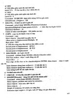
Figure 6.32 Performance of lattice reduction aided detection for QPSK system with N
T
=
N
R
= 4 (solid bold line: MLD performance, bold dashed line: linear detectors)
Simulation Results
Now, we want to compare the performance of the introduced LR approach to the detection
techniques already described in Chapter 5. We consider multiple antenna systems with an
identical number of receive and transmit antennas. Moreover, uncorrelated flat Rayleigh
fading channels between different pairs of transmit and receive antennas are assumed.
Note that no iterations according to the turbo principle are carried out so that we regard a
one-stage detector. If the loss compared to the maximum likelihood detector is large, the
performance can be improved by iterative schemes as shown in Chapter 5.
Figure 6.32 compares the BER performance of an uncoded 4-QAM system with N
T
=
N
R
= 4 antennas at the transmitter and receiver. Figure 6.32a summarizes the zero-forcing
results. The simple decorrelator (bold dashed curve) based on the original channel matrix H
shows the worst performance. It severely amplifies the background noise and cannot exploit
diversity and so the slope of the curve corresponds to a diversity degree of D = N
R
− N
T
+
1 = 1. The ZF-SQLD-SIC detection gains about 7 dB at 10
−2
compared to the decorrelator
but is still far away from the maximum likelihood performance. It can only partly exploit
the diversity as will be shown in Figure 6.33. The decorrelator based on the reduced channel
matrix H
red
labeled LR performs slightly worse than the ZF-SQLD-SIC at low SNRs and
much better at high SNRs.
5
At an error rate of 2 ·10
−3
, the gain already amounts to 4 dB.
On the one hand, the LR-aided decorrelator does not enhance the background noise very
much owing to the nearly orthogonal structure. On the other hand, it fully exploits the
diversity in all layers as indicated by the higher slope of the error rate curve.
Since the reduced channel matrix H
red
is not perfectly orthogonal, multilayer inter-
ference still disturbs the decision. Hence, a subsequent nonlinear successive interference
5
As already mentioned, the system representation by a reduced channel matrix requires a decision in the
transformed domain and a subsequent inverse transformation. Therefore, the whole detector is nonlinear although
a linear device was employed in the transformed domain.
318 MULTIPLE ANTENNA SYSTEMS
cancellation applying hard decisions (ZF-SQLD-SIC) can improve the performance by 1 dB.
The gain is not as high as for the conventional SQLD-SIC owing to the good condition
of H
red
.
Looking at the MMSE solutions in Figure 6.32b, we recognize that all curves move
closer to the MLD performance. The linear MMSE filter based on H performs worst, the
LR-based counterpart outperforms the MMSE-SQLD-SIC at high SNR. The LR-SQLD-
SIC improves the performance such that the MLD curve is reached. Thus, we can conclude
that the LR technique improves the performance significantly and that it is well suited for
enhancing the signal detection in environments with severe multiple access interference.
For the considered scenario, near-maximum likelihood performance is achieved with much
lower computational costs.
Next, we analyze how the different detectors exploit diversity. From Figure 6.27, we
know already that each layer experiences a different diversity degree for QLD-SIC-based
approaches. This is again illustrated in Figure 6.33 for the ZF and MMSE criteria. The
curves have been obtained by employing a genie-aided detector that perfectly avoids error
propagation. Hence, the error rates truly represent the different diversity degrees and do
not suffer from errors made in the previous detection steps.
The results for the LR-based detection are depicted with only one curve because the
error rates of all the layers are nearly identical. Hence, all layers experience the same
diversity degree of D = 4 (compare slope with SQLD-4) so that even the first layer can be
detected with high reliability. Since this layer dominates the average error rate especially
in the absence of a genie, this represents a major benefit compared to QLD-SIC schemes.
Wih reference to the MMSE solution, the differences are not as large but still observable.
At very low SNRs, the genie-aided MMSE-SQLD-SIC even outperforms the maximum
likelihood detector because no layer suffers from interference and decisions are made layer
by layer while the MLD has to cope with all layers simultaneously.
0 5 10 15 20
10
−5
10
−4
10
−3
10
−2
10
−1
10
0
0 5 10 15 20
10
−5
10
−4
10
−3
10
−2
10
−1
10
0
E
b
/N
0
in dB →E
b
/N
0
in dB →
BER →
BER →
a) ZF
b) MMSE
SQLD-SIC-1SQLD-SIC-1
SQLD-SIC-2SQLD-SIC-2
SQLD-SIC-3SQLD-SIC-3
SQLD-SIC-4SQLD-SIC-4
LR-SQLD-SICLR-SQLD-SIC
Figure 6.33 Illustration of diversity degree per layer for SQLD and lattice reduction aided
detection for QPSK system with N
T
= N
R
= 4 (solid bold line: MLD performance)
MULTIPLE ANTENNA SYSTEMS 319
0 5 10 15 20 25 30
10
−5
10
−4
10
−3
10
−2
10
−1
10
0
0 5 10 15 20 25 30
10
−5
10
−4
10
−3
10
−2
10
−1
10
0
E
b
/N
0
in dB →E
b
/N
0
in dB →
BER →
BER →
a) ZF
b) MMSE
SQLD-SICSQLD-SIC
LRLR
LR-SQLD-SICLR-SQLD-SIC
Figure 6.34 Performance of lattice reduction aided detection for 16-QAM system with
N
T
= N
R
= 4 (solid bold line: MLD performance, bold dashed line: linear detector)
Figure 6.34 shows the performance of the same system for 16-QAM. First, it has
to be mentioned that the computational complexity of LR itself is totally independent
of the size of the modulation alphabet. This is a major advantage compared to the ML
detector because its complexity grows exponentially with the alphabet size. Compared to
QPSK, larger SNRs are needed to achieve the same error rates. However, the relations
between the curves are qualitatively still the same. The LR-based SQLD-SIC gains 1 dB
compared to the LR-based decorrelator of 2 dB for the MMSE solution. The SQLD-SIC
approach based on the original channel matrix is clearly outperformed but the MLD perfor-
mance is not obtained anymore and a gap of approximately 1 dB remains for the MMSE
approach.
Finally, a larger system with N
T
= N
R
= 6 and 16-QAM is considered. Figure 6.35
shows that the LR-based SQLD-SIC still outperforms the detector based on H but the
gap to the maximum likelihood detector becomes larger. The reason is the efficient but
suboptimum LLL algorithm (see Appendix C.3) used for the LR. It loses in performance
for large matrices because the inherent sorting gets worse. This is also the reason why
the LR-aided detector was not introduced in the context of multiuser detection in CDMA
systems in Chapter 5. The considered CDMA systems have much more inputs and outputs
(larger system matrices S) than the multiple antenna systems analyzed here so that no
advantage could have been observed when compared with the conventional SQLD-SIC.
6.4 Linear Dispersion Codes
A unified description for space–time coding and spatial multilayer transmission can be
obtained by LD codes that were first introduced by Hassibi and Hochwald (2000, 2001,
2002). Moreover, this approach offers the possibility of finding a trade-off between diversity
and multiplexing gain (Heath and Paulraj 2002). Generally, the matrix X describing the
320 MULTIPLE ANTENNA SYSTEMS
0 5 10 15 20 25 30
10
−5
10
−4
10
−3
10
−2
10
−1
10
0
0 5 10 15 20 25 30
10
−5
10
−4
10
−3
10
−2
10
−1
10
0
E
b
/N
0
in dB →E
b
/N
0
in dB →
BER →
BER →
a) ZF
b) MMSE
SQLD-SICSQLD-SIC
LR-SQLD-SICLR-SQLD-SIC
Figure 6.35 Performance of lattice reduction aided detection for 16-QAM system with
N
T
= N
R
= 6 (solid bold line: MLD performance)
space–time codeword or the BLAST transmit matrix is set up of K symbols a
µ
.Aswe
know from STTCs, a linear description requires the symbols a
µ
and their conjugate complex
counterparts or, alternatively, the real-valued representation by a
µ
and a
µ
with a
µ
= a
µ
+
ja
µ
. The codeword can be constructed by
X =
K
µ=1
B
c
1,µ
· a
µ
+ B
c
2,µ
· a
∗
µ
=
K
µ=1
B
r
1,µ
· a
µ
+ B
r
2,µ
· a
µ
=
2K
µ=1
B
r
µ
· a
r
µ
. (6.85)
The dispersion matrices B
c
i,µ
with i = 1, 2 are used for the complex description, where the
index i = 1 is associated with the original symbols and i = 2 with their complex conjugate
versions. The real-valued alternative in (6.85) also uses 2K matrices B
r
i,µ
and distinguishes
between real and imaginary parts by using indices i = 1, 2, respectively. A generalization
is obtained with the right-hand side in (6.85) assuming a set of 2K real-valued symbols
a
r
µ
with 1 ≤ µ ≤ 2K.ThefirstK elements may represent the real parts a
µ
and the second
K elements the imaginary parts a
µ
. It depends on the choice of the matrices whether a
space–time code, a multilayer transmission, or a combination of both is implemented. In
the following part, a few examples, in order to illustrate the manner in which LD codes
work, are presented.
6.4.1 LD Description of Alamouti’s Scheme
First, we look at the Alamouti’s STBC. As we know, the codeword X
2
comprises K = 2
symbols that are arranged over two antennas and two time slots. The matrix has the form
X
2
=
a
1
−a
∗
2
a
2
a
∗
1
=
a
1
0
0 a
1
+
0 −a
2
a
2
0
+
ja
1
0
0 −ja
1
+
0 ja
2
ja
2
0
MULTIPLE ANTENNA SYSTEMS 321
For the complex-valued description, we obtain the matrices
B
c
1,1
=
10
00
, B
c
1,2
=
00
10
, B
c
2,1
=
0 −1
00
, B
c
2,2
=
00
01
.
Consequently, the real-valued case uses the matrices
B
r
1
=
10
01
, B
r
2
=
0 −1
10
, B
r
3
=
j 0
0 −j
, B
r
4
=
0 j
j 0
where B
r
1
is associated with a
1
, B
r
2
with a
2
, B
r
3
with a
1
,andB
r
4
with a
2
.Inthesame
way, dispersion matrices can be developed for any linear STBC. However, codes without
orthogonal designs may require high computational decoding costs because simple matched
filtering is not optimum anymore.
6.4.2 LD Description of Multilayer Transmissions
Next, we take a look at the multilayer transmission, for example, the BLAST architecture.
Following the description of the previous section, N
T
independent symbols are simulta-
neously transmitted at each time instant. Hence, each codeword matrix has exactly L = 1
columns so that the dispersion matrices reduce to column vectors. For the complex-valued
variant, the vector B
c
1,µ
consists only of zeros with a single one at the µth position while
B
c
2,µ
= 0
N
T
×1
holds. For the special case of N
T
= 2, we obtain
B
c
1,1
=
1
0
, B
c
1,2
=
0
1
, B
c
2,1
=
0
0
, B
c
2,2
=
0
0
.
On the contrary,
B
r
1
=
1
0
, B
r
2
=
0
1
, B
r
3
=
j
0
, B
r
4
=
0
j
holds for the real-valued case.
6.4.3 LD Description of Beamforming
Even beamforming in multiple-input multiple-output (MINO) systems can be described
by linear dispersion codes. While the matrices B
c,r
µ
used so far have been independent of
the instantaneous channel matrix, the transmitter certainly requires channel state informa-
tion (CSI) when beamforming shall be applied. Considering a MISO system, the channel
matrix reduces to a row vector h
that directly represents the singular vector to be used for
beamforming (see page 306). Using the complex notation, the LD description becomes
x = B
c
1
· a
1
⇒ y = h · B
c
1
· a
1
+ n
where the matrix B
c
1
= h
H
reduces to a column vector. Since a
1
= a
1
+ ja
1
holds, the
real-valued notation has the form
x =
2
µ=1
B
r
µ
· a
r
µ
= B
r
1
· a
1
+ B
r
2
· a
1
with B
r
1
= h
H
and B
r
2
= jh
H
. For MIMO systems with more than one receive antenna, the
right singular vector corresponding to the largest singular vector has to be chosen.
322 MULTIPLE ANTENNA SYSTEMS
6.4.4 Optimizing Linear Dispersion Codes
Using the real-valued description, the received data block can generally be expressed with
Y = H · X + N = H ·
2K
µ=1
B
r
µ
· a
r
µ
+ N. (6.86)
It consists of N
R
rows according to the number of receive antennas and L columns denoting
the duration of a space–time codeword. Stacking the columns of the matrices B
r
µ
in (6.86)
into long vectors with the operator
vec{X}=vec
x
1
··· x
n
=
x
1
.
.
.
x
n
delivers
2K
µ=1
vec
B
r
µ
· a
r
µ
= B
r
· a
r
(6.87)
where the vector a
r
comprises all data symbols a
r
µ
and the matrix B
r
contains in column
µ the vector vec{B
r
µ
}. Since the time instants are not arranged in columns anymore but
stacked one below the other, the channel matrix H has to be enlarged by repeating it L
times. This can be accomplished by the Kronecker product that is generally defined as
A ⊗ B =
A
1,1
· B ··· A
1,N
· B
.
.
.
.
.
.
A
M,1
· B ··· A
M,N
· B
.
Applying the vec-operator to the matrices Y and N leads to the expression
y = vec
{
Y
}
=
(
I
L
⊗ H
)
· B
r
· a
r
+ vec
{
N
}
=
˜
H · B
r
· a
r
+ vec
{
N
}
. (6.88)
The optimization of LD codes can be performed with respect to different measures. Looking
at the ergodic capacity already known from Section 2.3 on page 73, we have to choose the
matrix B
r
according to
B
r
= argmax
B
log
2
det
I +
σ
2
N
σ
2
A
·
˜
HBB
H
˜
H
H
(6.89a)
subject to a power constraint, for example,
tr
2K
µ=1
B
r
µ
(B
r
µ
)
H
= K. (6.89b)
Results for this optimization can be found in Hassibi and Hochwald (2000, 2001, 2002).
A different approach considering the error rate performance as well is presented in Heath
and Paulraj (2002). Generally, the obtained LD codes do not solely pursue diversity or
multiplexing gains but can achieve a trade-off between both aspects.
MULTIPLE ANTENNA SYSTEMS 323
6.4.5 Detection of Linear Dispersion Codes
For the special case when LD codes are used to implement orthogonal STBCs, simple
matched filters as explained in Section 6.2 represent the optimal choice. For multilayer
transmissions as well as the general case, we can combine all matrices before the data
vector a
r
in (6.88) into an LD channel matrix H
LD
and obtain
y = H
ld
· s + n. (6.90)
With (6.90), we can directly apply multilayer detection techniques from Sections 5.4 and
6.3.
6.5 Information Theoretic Analysis
In this section, the theoretical results of Section 2.3 for multiple antenna systems are
illustrated. We consider uncorrelated as well as correlated frequency-nonselective MIMO
channels and determine the channel capacities for Gaussian distributed input signals for
different levels of channel knowledge at the transmitter. Perfect channel knowledge at the
receiver is always assumed.
6.5.1 Uncorrelated MIMO Channels
First, the uncorrelated SIMO channel is addressed, that is, we obtain the simple receive
diversity. The capacity can be directly obtained from (2.78) in Section 2.3. An easier
way is to consider the optimal receive filter derived in Section 1.5 performing maximum
ratio combining of all N
R
signals. This results in an equivalent SISO fading channel whose
instantaneous SNR depends on the squared norm h[k]
2
. Hence, the instantaneous channel
capacity has the form
C[k] = log
2
1 +h[k]
2
E
s
N
0
. (6.91)
Ergodic capacities and outage probabilities can be determined from (6.91) by using the
statistics of h[k]
2
. For independent Rayleigh fading channels, the random variable is
chi-squared distributed with 2N
R
degrees of freedom.
Figure 6.36a shows the ergodic capacity for an uncorrelated SIMO channel with up to
four outputs versus the SNR per receive antenna. We observe that the capacity increases
with growing number of receive antennas owing to the higher diversity degree and the
array gain. The latter one shifts the curves by 10 log
10
(N
R
) to the left, that is, doubling
the number of receive antennas leads to an array gain of 3 dB. Concentrating only on the
diversity gain, we have to depict the curves versus the SNR after maximum ratio combining
as shown in Figure 6.36b. We recognize that the capacity gains due to diversity are rather
small and the slope of the curves is independent of N
R
. Hence, the capacity enhancement
depends mainly logarithmically on the SNR because the channel vector h obviously has
rank r = 1owingtoN
T
= 1, that is, only one nonzero eigenvalue exists so that only one
data stream can be transmitted at a time. In this scenario, multiple receive antennas can only
increase the link reliability, leading to moderate capacity enhancements. Nevertheless, the
outage probability can be significantly decreased by diversity techniques (cf. Section 1.5).
324 MULTIPLE ANTENNA SYSTEMS
0 10 20 30
0
2
4
6
8
10
12
0 10 20 30
0
2
4
6
8
10
12
E
s
/N
0
in dB →
C →
C →
N
R
= 1N
R
= 1
N
R
= 2N
R
= 2
N
R
= 3N
R
= 3
N
R
= 4N
R
= 4
E
s
/N
0
in dB per receive antenna
a) SNR per receive antenna
b) SNR after combining
Figure 6.36 Channel capacity versus SNR for i.i.d. Rayleigh fading channels, N
T
= 1
transmit antenna, and N
R
receive antennas
On the contrary, Figure 6.37a shows the capacity for a system with N
T
= 4 transmit
antennas and different number of receive antennas with i.i.d. channels where the total
transmit power is fixed at E
s
/T
s
. First, we take a look at the case of a single receive and
N
T
= 4 transmit antennas. The instantaneous capacity of this scheme is
C[k] = log
2
1 +
h[k]
2
N
T
·
E
s
N
0
(6.92)
because the transmit power is fixed independent of N
T
. The comparison with Figure 6.36b
that normalizes the SNR to the number of receive antennas shows that the combinations
N
R
= 4,N
T
= 1andN
R
= 1,N
T
= 4 provide identical results, that is, the system is
symmetric. However, Figure 6.36a illustrates differences of 10 log
10
(N
R
) dB between the
curves. This discrepancy can be explained by the fact that perfect channel knowledge at the
receiver was assumed, allowing receive beamforming and delivering an array gain while
no CSI was assumed at the transmitter. Obviously, transmit diversity schemes provide no
array gain.
The capacity of the general case with multiple receive and transmit antennas can be
directly calculated with (2.78) on page 74. From Figure 6.37, we observe that the slope
of the curve grows with increasing N
T
according to the parameter m = min[N
R
,N
T
]. This
indicates that m parallel virtual channels exist over which parallel data streams can be
transmitted. Hence, the data rate is multiplied by m so that multiple antenna systems may
increase the capacity linearly with m, while the SNR may increase it only logarithmically.
This emphasizes the high potential of multiple antennas at the transmitter and receiver.
Figure 6.37b demonstrates the influence of perfect channel knowledge at the transmitter,
allowing the application of the waterfilling principle introduced in Section 2.3. A compar-
ison with Figure 6.37a shows that the capacity is improved only for N
T
>N
R
and high
SNR. If we have more receive than transmit antennas, the best strategy for high SNRs is
MULTIPLE ANTENNA SYSTEMS 325
0 10 20 30
0
5
10
15
20
25
30
35
0 10 20 30
0
5
10
15
20
25
30
35
E
s
/N
0
in dB →E
s
/N
0
in dB →
C →
C →
N
R
= 1N
R
= 1
N
R
= 2N
R
= 2
N
R
= 3N
R
= 3
N
R
= 4N
R
= 4
a) no CSI at transmitter
b) waterfilling
Figure 6.37 Channel capacity versus SNR for i.i.d. Rayleigh fading channels, N
T
= 4
transmit antennas, and N
R
receive antennas (SNR per receive antenna)
to distribute the power equally over all antennas. Since this is automatically done in the
absence of channel knowledge, waterfilling provides no additional gain for N
R
= N
T
= 4.
Similar to Section 1.5, we can analyze the outage probability of multiple antenna sys-
tems, that is, the probability P
out
that a certain rate R is not achieved. From Chapter 2,
we know that diversity decreases the outage probability because the SNR variations are
reduced. This behavior can also be observed from Figure 6.38. Especially figure 6.38a
emphasizes that diversity reduces the outage probability and the rapid growth of the curves
starts later at higher rates R. However, they also become steeper, that is, a link becomes
quickly unreliable if a certain rate is exceeded. Generally, increasing max[N
T
,N
R
] while
keeping the minimum constant does not lead to an additional eigenmode and diversity
increases the link reliability. On the contrary, increasing min[N
T
,N
R
] shifts the curves to
the right because the number of virtual channels and, therefore, the data rate is increased.
A strange behavior can be observed in Figure 6.39 for high rates R above the ergodic
capacity C. Here, increasing the number of transmit antennas, and, thus the diversity degree,
does not lead to a reduction of P
out
. Comparing the curves for N
R
= 1andN
T
= 1, 2, 3, 4
(MISO channels) directly, we recognize that P
out
even increases with N
T
. The reason is that
the variations of the SNR are reduced so that very low and also very high instantaneous
values occur more rarely. Therefore, very high rates are obtained less frequently than for
low diversity degrees.
6.5.2 Correlated MIMO Channels
Correlated MIMO systems are now considered. This scenario occurs if the antenna elements
are arranged very close to each other and the impinging waves arrive from a few dominant
directions. Hence, we do not have a diffuse electromagnetic field with a uniform distribution
of the angles of arrival, but preferred directions θ
µ
with a certain angle spread θ
µ
.
326 MULTIPLE ANTENNA SYSTEMS
0 4 8 12 16
0
0.2
0.4
0.6
0.8
1
0 4 8 12 16
0
0.2
0.4
0.6
0.8
1
0 4 8 12 16
0
0.2
0.4
0.6
0.8
1
0 4 8 12 16
0
0.2
0.4
0.6
0.8
1
P
out
→
P
out
→
P
out
→
P
out
→
R →R →
R →R →
a) N
T
= 1
b) N
T
= 2
c) N
T
= 3
d) N
T
= 4
N
R
= 1N
R
= 1
N
R
= 1N
R
= 1
N
R
= 2N
R
= 2
N
R
= 2N
R
= 2
N
R
= 3N
R
= 3
N
R
= 3N
R
= 3
N
R
= 4N
R
= 4
N
R
= 4N
R
= 4
Figure 6.38 Outage probability versus rate R in bits/s/Hz for i.i.d. Rayleigh fading channels
and a signal-to-noise ratio of 10 dB
Figure 6.40 compares the ergodic capacity of i.i.d. and correlated 4 ×4 MIMO channels
for different levels of channel knowledge at the transmitter. First, it can be seen that perfect
channel knowledge (CSI) at the transmitter does not increase the capacity of uncorrelated
channels except for very low SNRs. Hence, the best strategy over a wide range of SNRs
is to transmit four independent data streams.
With reference to the correlated MIMO channel, we can state that channel knowledge
at the transmitter increases the capacity. Hence, it is necessary to have CSI at the trans-
mitter for correlated channels. Moreover, the ergodic capacity is greatly reduced because
of correlations. Only for extremely low SNRs, correlations can slightly improve the capac-
ity because in this specific scenario, increasing the SNR by beamforming is better than
transmitting parallel data streams.
Finally, we analyze the performance when only long-term channel knowledge is avail-
able at the transmitter. This means that we do not know the instantaneous channel matrix
H[k] but its covariance matrix
H H
= E{H
H
H}. This approach is motivated by the fact
MULTIPLE ANTENNA SYSTEMS 327
0 2 4 6 8
0
0.2
0.4
0.6
0.8
1
P
out
→
R →
N
T
= 1
N
T
= 2
N
T
= 3
N
T
= 4
Figure 6.39 Outage probability versus rate R in bits/s/Hz for N
R
= 1 and i.i.d. Rayleigh
fading channels and a signal-to-noise ratio of 10 dB
0 5 10 15 20 25 30
0
5
10
15
20
25
30
35
E
s
/N
0
in dB →
C →
i.i.d., noCSI
i.i.d., CSI
corr., noCSI
corr., CSI
corr., lt CSI
Figure 6.40 Channel capacity versus SNR for i.i.d. and correlated Rayleigh fading channels,
N
T
= 4 transmit, and N
R
= 4 receive antennas
that long-term statistics such as angle of arrivals remain constant for a relatively large
duration and can therefore be accurately estimated. Moreover, it is often assumed that these
long-term properties are identical for uplink and downlink allowing the application of
ˆ
H H
measured in the downlink for the uplink transmission.
From Figure 6.40, we see that the knowledge of the covariance matrix (lt CSI) leads to
the same performance as optimal CSI for correlated channels. In the absence of correlations,
only instantaneous channel information can improve the capacity and long-term statistics
do not help at all.
328 MULTIPLE ANTENNA SYSTEMS
6.6 Summary
In this chapter, we analyzed the potential of multiple antenna techniques for point-to-point
communications. Starting with diversity concepts, we saw that spatial diversity is obtained
with multiple antennas at the receiver as well as the transmitter. Space–time transmit
diversity schemes do not require channel knowledge at the transmitter but provide the
full diversity degree. We distinguished orthogonal STBCs and STTCs. The latter yield an
additional coding gain at the expense of a much higher decoding complexity.
While diversity increases the link reliability, the great potential of MIMO systems can be
exploited by multilayer transmissions discussed in Section 6.3. Here, parallel data streams
termed layers are transmitted over different antennas. Without channel knowledge at the
transmitter, the detection problem represents the major challenge. Besides multilayer (or
multiuser) detection techniques already introduced in Chapter 5, a new algorithm based on
the LR has been derived. It shows superior performance at moderate complexity.
In Section 6.4, we demonstrated that LD codes provide a unified description of
space–time coding and multilayer concepts. With this concept, the trade-off between diver-
sity and multilayer gains can be optimized. Finally, the channel capacity of MIMO systems
has been illustrated by numerical examples. It turned out that the rank of the channel
matrix determines the major capacity improvement compared to SISO systems and that
pure diversity concepts only lead to a minor capacity growth.
Appendix A
Channel Models
A.1 Equivalent Baseband Representation
The output of the receive filter g
R
(t) can be expressed by
y(t) = g
R
(t) ∗
y
+
BP
(t)
1
√
2
e
−jω
0
t
(A.1)
= g
R
(t) ∗
y
BP
(t) +jH
{
y
BP
(t)
}
1
√
2
e
−jω
0
t
= g
R
(t) ∗
h
BP
(t, τ) ∗x
BP
(t) +n
BP
(t)
+jH
{
h
BP
(t, τ) ∗x
BP
(t) +n
BP
(t)
}
1
√
2
e
−jω
0
t
. (A.2)
The convolution in (A.2) is defined in (1.7)
h(t, τ) ∗ x(t) =
∞
0
h(t, τ)x(t −τ)dτ.
Exploiting the linearity of the Hilbert transform and the property H
{
a(t) ∗ b(t)
}
= a(t) ∗
H
{
b(t)
}
yields
y(t) = g
R
(t) ∗
h
BP
(t, τ) ∗x
BP
(t) +jh
BP
(t, τ) ∗H
{
x
BP
(t)
}
+n
+
(t)
1
√
2
e
−jω
0
t
= g
R
(t) ∗
h
BP
(t, τ)e
−jω
0
t
∗ x(t) + n(t) (A.3)
with x(t) = x
+
(t)
1
√
2
e
−jω
0
t
equivalent to (1.1) and
n(t) = g
R
(t) ∗
n
+
(t)
1
√
2
· e
−jω
0
t
. (A.4)
Wireless Communications over MIMO Channels Vo l k e r K
¨
uhn
2006 John Wiley & Sons, Ltd
330 CHANNEL MODELS
Owing to G
R
(jω) = 0for|ω| >B, B f
0
and property (1.9) of the analytical signal,
g
R
(t) ∗
h
BP
(t, τ)e
−jω
0
t
= F
−1
{
G
R
(jω) ·H
BP
(t, jω −jω
0
)
}
= F
−1
G
R
(jω) ·
1
2
H
+
BP
(t, jω −jω
0
)
= g
R
(t) ∗
1
2
h
+
BP
(t, τ)e
−jω
0
t
= g
R
(t) ∗h(t, τ ) (A.5)
holds. Thus, we get
y(t) = g
R
(t) ∗h(t, τ ) ∗x(t) + n(t) (A.6)
= T
s
·
k
x[k] ·
g
R
(t) ∗h(t, τ ) ∗g
T
(t −kT
s
)
+ n(t). (A.7)
The twofold convolution can be interpreted as a single filter
˜
h(t, kT
s
) = g
R
(t) ∗h(t, τ ) ∗g
T
(t −kT
s
) (A.8)
and (A.7) becomes
y(t) = T
s
·
k
x[k] ·
˜
h(t, kT
s
) + n(t). (A.9)
A.2 Typical Propagation Profiles for Outdoor Mobile
Radio Channels
In order to receive realistic parameters of mobile radio channels, extensive measurements
have been carried out by COST 207 (European Cooperation in the Fields of Scientific and
Technical Research) (COST 1989) for the global system for mobile communications GSM.
The obtained power delay profiles are listed in Table A.1 and represent typical propagation
scenarios.
Table A.1 Power delay profile of COST 207 (COST 1989)
(delays τ in µs)
profile power delay profile
h, h
(τ )
Rural Area (RA)
9.21 · exp(−9.2τ) 0 ≤ τ<0.7
0else
Typical Urban (TU)
exp(−τ) 0 ≤ τ<7
0else
Bad Urban (BU)
0.67 · exp(−τ) 0 ≤ τ<5
0.335 · exp(5 −τ) 5 ≤ τ<10
0else
Hilly Terrain (HT)
3.08 · exp(−3.5τ) 0 ≤ τ<2
0.1232 · exp(15 −τ) 15 ≤ τ<20
0else
CHANNEL MODELS 331
Table A.2 Doppler power spectrum of COST 207 (COST 1989)
delay Doppler power spectrum
hh
(f
d
)
0 <τ <0.5 µs
A
√
1−(f
d
/f
dmax
)
2
|f
d
|≤f
dmax
0else,
0.5 <τ <2 µs A · exp
−
(f
d
+0.8f
dmax
)
2
2(0.05f
dmax
)
2
+
A
10
· exp
−
(f
d
−0.4f
dmax
)
2
2(0.1f
dmax
)
2
τ>2 µs B · exp
−
(f
d
−0.7f
dmax
)
2
2(0.1f
dmax
)
2
+
B
31.6
· exp
−
(f
d
+0.4f
dmax
)
2
2(0.15f
dmax
)
2
Rural Area (τ = 0)
0.41
2πf
dmax
√
1−(f
d
/f
dmax
)
2
+ 0.91 · δ(f
d
− 0.7f
dmax
)
Table A.3 Propagation conditions for UMTS in multipath fading environments
(3GPP 2005b), delays τ in ns and rel. powers |h|
2
in dB, f
d
classically distributed
v = 3km/h v = 3km/h v = 120 km/h v = 3km/h v = 250 km/h
τ |h|
2
τ |h|
2
τ |h|
2
τ |h|
2
τ |h|
2
0 0 0 00 0 000 0
976 −10 976 0 260 −3 976 0 260 −3
20000 0 521 −6 521 −6
781 −9 781 −9
Equivalent results were obtained for the Doppler power spectra listed in Table A.2.
Principally, the statistical characteristics of the Doppler power spectra are affected by the
delay τ . For delays smaller than 0.5 µs,
hh
(f
d
) has a distribution according to the Jakes
spectrum, while for larger τ Gaussian distributions with different means and variances
occur. The rural area (RA) scenario represents a special case because it is characterized by
a line-of-sight link (Rice fading).
According to the requirements of the universal mobile telecommunication sys-
tem (UMTS) standard, different propagation scenarios were defined. They are summarized
in Table A.3. Five cases are distinguished that differ with respect to velocity and the number
of taps.
A.3 Moment-Generating Function for Ricean Fading
The channel coefficient h of a frequency-nonselective Ricean fading channel with average
power P and Rice factor K has the form given in (1.28)
h =
P
K + 1
·
√
K + α
.
It consists of two parts, a constant line-of-sight component and a fading component
represented by the factor α whose real and imaginary parts are statistically independent
zero-mean Gaussian processes each with variance 1/2. Hence, the real part H
of H is
332 CHANNEL MODELS
Gaussian distributed
p
H
(ξ) =
1
2πσ
2
H
· exp
−
ξ −
PK
K+1
2
2σ
H
2
=
K +1
πP
· exp
−
ξ
K + 1
P
−
√
K
2
(A.10a)
with mean
√
PK/(1 +K) and variance σ
2
H
= P/[2(K + 1)], while the imaginary part H
is Gaussian distributed with the same variance but zero mean.
p
H
(ξ) =
1
2πσ
2
H
· exp
−
ξ
2
2σ
2
H
=
K + 1
πP
· exp
−
(K + 1)ξ
2
P
(A.10b)
In order to calculate the density of |H|
2
, we have to deal with the densities of (H
)
2
and
(H
)
2
. In Papoulis (1965), the general condition
p
X
2
(ξ) =
1
2
√
ξ
·
p
X
ξ
+ p
X
−
ξ
(A.11)
between the pdf of a process X and the pdf of X
2
is given. With (A.11), we obtain for the
squared real part a noncentral chi-square distribution with one degree of freedom
p
H
2
(ξ) =
K + 1
πPξ
· exp
−
ξ(K + 1)
P
− K
· cosh
2
ξK(K + 1)
P
(A.12a)
and for the squared imaginary part a central chi-square distribution with one degree of
freedom
p
H
2
(ξ) =
K + 1
πPξ
· exp
−
ξ(K + 1)
P
. (A.12b)
Since the squared magnitude of H is obtained by adding the squared magnitudes of
the real and imaginary parts, their probability densities have to be convolved. This is
equivalent to multiplying the corresponding moment-generating functions. They have the
form (Proakis 2001)
M
H
2
(s) =
K +1
K +1 − sP
· exp
sKP
(K + 1) − sP
(A.13a)
and
M
H
2
(s) =
K + 1
K + 1 −sP
. (A.13b)
Consequently, we obtain the overall moment-generating function
M
|H|
2
(s) =
K +1
K +1 − sP
· exp
sKP
(K + 1) − sP
. (A.14)
Appendix B
Derivations for Information
Theory
B.1 Chain Rule for Entropies
Let X
1
, X
2
,uptoX
n
be random variables belonging to a joint probability Pr{X
1
, ,X
n
},
the chain rule for entropy has the form:
¯
I(X
1
, X
2
, , X
n
) =
n
i=1
¯
I(X
i
| X
i−1
···X
1
). (B.1)
Proof: We simply repeat the application of the chain rule for two random variables.
¯
I(X
1
, X
2
) =
¯
I(X
1
) +
¯
I(X
2
| X
1
)
¯
I(X
1
, X
2
, X
3
) =
¯
I(X
1
) +
¯
I(X
2
, X
3
| X
1
)
=
¯
I(X
1
) +
¯
I(X
2
| X
1
) +
¯
I(X
3
| X
1
, X
2
)
.
.
.
¯
I(X
1
, X
2
, , X
n
) =
¯
I(X
1
) +
¯
I(X
2
, ,X
n
| X
1
)
=
¯
I(X
1
) +
¯
I(X
2
| X
1
) +
¯
I(X
3
, ,X
n
| X
1
, X
2
)
=
n
i=1
¯
I(X
i
| X
i−1
···X
1
).
B.2 Chain Rule for Information
The general chain rule for information is as follows (Cover and Thomas 1991):
¯
I(X
1
, ,X
n
;Z) =
n
i=1
¯
I(X
i
;Z |
¯
I(X
i−1
, ,X
1
). (B.2)
Wireless Communications over MIMO Channels Vo l k e r K
¨
uhn
2006 John Wiley & Sons, Ltd
334 DERIVATIONS FOR INFORMATION THEORY
Proof: We apply the chain rule for entropies
¯
I(X
1
, ,X
n
;Z) =
¯
I(X
1
, ,X
n
) −
¯
I(X
1
, ,X
n
| Z)
=
n
i=1
¯
I(X
i
| X
i−1
···X
1
) −
n
i=1
¯
I(X
i
| X
i−1
···X
1
, Z)
=
n
i=1
¯
I(X
i
| X
i−1
···X
1
) −
¯
I(X
i
| X
i−1
···X
1
, Z)
=
n
i=1
¯
I(X
i
;Z | X
i−1
···X
1
).
B.3 Data-Processing Theorem
Data-processing theorem: We consider a Markovian chain X → Y → Z where X and Z
are independent given Y,thatis,
¯
I(X ;Z | Y) = 0. The data-processing theorem states the
following:
¯
I(X ;Y) ≥
¯
I(X ;Z). (B.3)
Proof:
The mutual information
¯
I(X ;Y, Z) can be extended with the chain rule in two differ-
ent ways:
¯
I(X ;Y, Z) =
¯
I(X ;Z) +
¯
I(X ;Y | Z) =
¯
I(X ;Y) +
¯
I(X ;Z | Y). (B.4)
Owing to the condition
¯
I(X ;Z | Y) = 0, we see from (B.4)
¯
I(X ;Y) =
¯
I(X | Z) +
¯
I(X ;Y | Z)
≥0
. (B.5)
Since entropies are always nonnegative,
¯
I(X ;Y | Z) ≥ 0 holds and we obtain the inequality
¯
I(X ;Y) ≥
¯
I(X | Z). (B.6)
Appendix C
Linear Algebra
C.1 Selected Basics
This appendix summarizes some basic results of linear algebra. It is not comprehensive and
focuses only on topics needed in this book. Unless otherwise stated, we consider complex
vectors and matrices. An N × N identity matrix is denoted by I
N
, 0
N×M
is an N × M
matrix containing only zeros and 1
N×M
a matrix of the same size consisting only of ones.
Definition C.1.1 (Determinant) A determinant uniquely assigns a real or complex-valued
number det(A) to an N × N matrix A. The determinant is zero if a row (column) only consists
of zeros or if it can be represented as a linear combination of other rows (columns). The
determinant of a product of square matrices is identical to the product of the corresponding
determinants
det(AB) = det(A) · det(B). (C.1)
According to Telatar (1995), we can rewrite (C.1) as
det(I + AB) = det(I + BA). (C.2)
Definition C.1.2 (Hermitian Operation) The Hermitian of a matrix (vector) is defined as
the transposed matrix (vector) with complex conjugate elements
A
H
=
A
∗
T
and x
H
=
x
∗
T
(C.3)
The following rules exist:
•
(
µA + νB
)
H
= µ
∗
A
H
+ ν
∗
B
H
•
(
AB
)
H
= B
H
A
H
•
A
H
H
= A
•
A
−1
H
=
A
H
−1
• In relation to real-valued matrices, the Hermitian form equals the transposed form:
A
H
= A
T
.
Wireless Communications over MIMO Channels Vo l k e r K
¨
uhn
2006 John Wiley & Sons, Ltd
336 LINEAR ALGEBRA
Definition C.1.3 (Inner Product) The inner product or dot product (Golub and van Loan
1996) of two complex N × 1 vectors x =
x
1
,x
2
, ,x
N
T
and y =
y
1
,y
2
, ,y
N
T
is
defined by
x
H
y =
N
i=1
x
∗
i
y
i
(C.4)
where x
∗
i
denotes the complex conjugate value of x
i
.
The definition of the inner product allows the calculation of the length of a vector
consisting of complex elements:
x=
√
x
H
x =
|x
1
|
2
+|x
2
|
2
+···+|x
N
|
2
. (C.5)
Two vectors x and y are called unitary, if their inner product is zero (x
H
y = 0). This is a
complex generalization of the orthogonality of real-valued vectors (x
T
y = 0) and sometimes
called conjugated orthogonality (Zurm
¨
uhl and Falk 1992). For real vectors, the unitary and
orthogonal properties are identical.
Definition C.1.4 (Spectral norm) The spectral norm or
2
norm of an arbitrary N × M
matrix A is defined as (Golub and van Loan 1996)
A
2
= sup
x=0
AX
x
. (C.6)
It describes the maximal amplification of a vector x that experiences a linear transformation
by A. The spectral norm has the following basic properties.
• The spectral norm of a matrix equals its largest singular value σ
max
A
2
= max
i
(σ
i
) = σ
max
. (C.7)
• The spectral norm of the inverse A
−1
is identical to the reciprocal of the smallest
singular value σ
min
of A
A
−1
2
=
1
min
i
(σ
i
)
=
1
σ
min
. (C.8)
Definition C.1.5 (Frobenius norm) The Frobenius norm of an arbitrary N × M matrix A
is defined as (Golub and van Loan 1996)
A
F
=
N
i=1
M
j=1
|A
i,j
|
2
=
tr{AA
H
}. (C.9)
Obviously, the squared Frobenius norm is A
2
F
= tr{AA
H
}.
Definition C.1.6 (Rank) For an arbitrary matrix A, the largest number r of linearly in-
dependent columns always equals the largest number of linearly independent rows. This
number r is called the rank of a matrix and is denoted by r = rank(A).
LINEAR ALGEBRA 337
From this definition, it follows directly that the rank of an N ×M matrix is always less
than or equal to the minimum of N and M:
r = rank(A) ≤ min(N, M). (C.10)
We can derive the following properties with the definition of rank(A):
• An N ×N matrix A is called regular if its determinant is nonzero and, therefore,
r = rank(A) = N holds. For regular matrices, the inverse A
−1
with A
−1
A = I
N×N
exists.
• If the determinant is zero, r = rank(A)<N holds and the matrix is called singular.
The inverse does not exist for singular matrices.
• For each N ×N matrix A of rank r, there exist at least one r × r submatrix whose
determinant is nonzero. The determinants of all (r +1) × (r + 1) submatrices of A
are zero.
• The rank of the product AA
H
is
rank(AA
H
) = rank(A). (C.11)
Definition C.1.7 (Eigenvalue Problem) The calculation of the eigenvalues λ
i
and the ei-
genvectors x
i
of a square N ×N matrix A is called eigenvalue problem. The goal is to find
a vector x that is proportional to Ax and, therefore, fulfills the eigenvalue equation
A · x = λ · x. (C.12)
This equation can be rewritten as
(
A − λ I
N
)
x = 0. Since we are looking for the nontrivial
solution x = 0, the columns of
(
A − λ I
N
)
have to be linearly dependent, resulting in the
equation det
(
A − λ I
N
)
= 0 that holds. Hence, the eigenvalues λ
i
represent the zeros of
the characteristic polynomial p
N
(λ) = det(A − λI
N
) of rank N . Each N × N matrix has
exactly N eigenvalues that need not be different.
For each eigenvalue λ
i
, the equation
A − λ
i
I
N
x
i
= 0 has to be solved with respect to
the eigenvector x
i
. There always exist solutions x
i
= 0. Besides x
i
, c · x
i
is also an eigen-
vector corresponding to λ
i
. Hence, we can normalize the eigenvectors to unit length.
The eigenvectors x
1
, ,x
k
belonging to different eigenvalues λ
1
, ,λ
k
are linearly inde-
pendent of each other (Horn and Johnson 1985; Strang 1988).
There exist the following relationships between the matrix A and its eigenvalues:
• The sum of all eigenvalues is identical to the sum of all N diagonal elements called
trace of a square matrix A
tr(A) =
r=N
i=1
A
i,i
=
r=N
i=1
λ
i
. (C.13)
338 LINEAR ALGEBRA
• If a square matrix A has full rank r = N, the product of its eigenvalues equals the
determinant of A:
r=N
i=1
λ
i
= det(A) (C.14)
If the matrix is rank deficient with r<N, the product of the nonzero eigenvalues
equals the determinant of the r × r submatrix of rank r.
• An eigenvalue λ
i
= 0 exists if and only if the matrix is singular, that is, det(A) = 0
holds.
Definition C.1.8 (Orthogonality) A real-valued matrix is called orthogonal, if its columns
are mutually orthogonal. Therefore, the inner product between different columns becomes
q
T
i
q
j
= 0. If all the columns of an orthogonal matrix have unit length,
q
T
i
q
j
= δ(i, j) (C.15)
holds and the matrix is called orthonormal. Orthonormal matrices are generally denoted by
Q and have the properties
Q
T
Q = I
N
⇔ Q
T
= Q
−1
. (C.16)
Definition C.1.9 (Unitary Matrix) A complex N ×N matrix with orthonormal columns is
called a unitary matrix U with the properties
U
H
U = UU
H
= I
N
⇔ U
H
= U
−1
(C.17)
The columns of U span an N-dimensional orthonormal vector space.
From the definition of a unitary matrix U, it follows that:
• all eigenvalues of U have unit length (|λ
i
|=1);
• unitary matrices are normal because UU
H
= U
H
U = I
N
holds;
• eigenvectors belonging to different eigenvalues are orthogonal to each other;
• the inner product x
H
y between two vectors remains unchanged if each vector is
multiplied with a unitary matrix U because (Ux)
H
(Uy) = x
H
U
H
Uy = x
H
y holds;
• the length of a vector does not change when multiplied with U: Ux=x;
• a random matrix B has the same statistical properties as the matrices BU and UB;
• the determinant of a unitary matrix amounts to det(U) = 1 (Blum 2000).
Definition C.1.10 (Hermitian Matrix) A square matrix A is called Hermitian if it equals
its complex conjugate transposed version.
A = A
H
(C.18)
LINEAR ALGEBRA 339
The real part of an Hermitian matrix is symmetric and the imaginary part is antisymmetric:
Re
{
A
}
= Re
{
A
}
T
and Im
{
A
}
=−Im
A
T
. (C.19)
Obviously, the symmetric and Hermitian properties are identical for real matrices.
Hermitian matrices have the following properties (Strang 1988):
• all diagonal elements A
i,i
are real;
• for each element, A
i,j
= A
∗
j,i
holds;
• for all complex vectors x, the number x
H
Ax is real;
• AA
H
= A
H
A holds because the matrix A is normal;
• the determinant det(A) is real;
• all eigenvalues λ
i
of an Hermitian matrix are real;
• the eigenvectors x
i
of a real symmetric matrix or an Hermitian matrix are orthogonal
to each other, if they belong to different eigenvalues λ
i
.
Definition C.1.11 (Eigenvalue Decomposition) An N ×N matrix A with N linear inde-
pendent eigenvectors x
i
can be transformed into a diagonal matrix (Horn and Johnson
1985). This can be accomplished by generating the matrix U whose columns comprise all
eigenvectors of A . It follows that
U
−1
AU = =
λ
1
λ
2
.
.
.
λ
N
(C.20)
with U =
(
x
1
, x
2
, ,x
N
)
. The eigenvalue matrix is diagonal and contains the eigenval-
ues of A on its diagonal.
From definition C.1.11, it follows directly that each matrix A can be expressed as A =
UU
−1
= UU
H
(eigenvalue decomposition).
Definition C.1.12 (c) A generalization of definition (C.1.11) for arbitrary N × M matrices
A is called singular value decomposition (SVD). A matrix A with rank r can be expressed
as
A = UV
H
(C.21)
with the unitary N × N matrix U and the unitary M × M matrix V.ThecolumnsofU
contain the eigenvectors of AA
H
and the columns of V contain the eigenvectors of A
H
A.
The matrix is an N ×M diagonal matrix with nonnegative, real-valued elements σ
k
on its
diagonal. Denoting the eigenvalues of AA
H
and, therefore, also of A
H
A with λ
k
, 1 ≤ k ≤ r,
the diagonal elements σ
k
are the positive square roots of λ
k
σ
k
=
λ
k
1 ≤ k ≤ r. (C.22)
340 LINEAR ALGEBRA
They are called singular values of A. For the matrix containing the singular values, we
obtain
=
σ
1
0 0 0 0
0 σ
2
0 00
.
.
.
.
.
.
.
.
.
.
.
.
.
.
.
00 σ
r
0 0
00 0
0 0
.
.
.
.
.
.
.
.
.
.
.
.
.
.
.
00 0
0 0
r rows
M-r rows
(C.23)
r columns
N-r columns
Definition C.1.13 (Spectral Theorem) A real symmetric matrix can be transformed into a
diagonal matrix by multiplying with an orthogonal matrix
A = QQ
−1
= QQ
T
(C.24)
and every Hermitian matrix can be transformed into a diagonal matrix by multiplying with
a unitary matrix:
A = UU
−1
= UU
H
. (C.25)
Owing to definitions C.1.1 and C.1.9, the determinant of A becomes
det(A) = det(U) det() det(U
−1
) = det(). (C.26)
Definition C.1.14 (Square Root of a Matrix) An N × M matrix B is called square root
of an N × N matrix A,if
BB
H
= A (C.27)
holds. From
A
H
=
BB
H
H
=
B
H
H
B
H
= A (C.28)
we see that A is always Hermitian and from definition C.1.6, it follows that the rank of A is
rank(A) = rank(BB
H
) = rank(B). (C.29)
Definition C.1.15 (Positive Semidefinite Matrix) A Hermitian N ×N matrix A is called
positive semidefinite, PSD if
x
H
Ax ≥ 0 (C.30)
holds for each vector x ∈ C
N
.
The following rules are valid:
• AmatrixA is positive semidefinite, if its square root B according to definition C.1.14
exists, so that it is always Hermitian.
• A Hermitian matrix is positive semidefinite if and only if all eigenvalues are real and
nonnegative, so that λ
i
≥ 0 for 1 ≤ i ≤ N holds.
LINEAR ALGEBRA 341
u
x
y = x
−2uu
H
x
Figure C.1 Illustration of Householder reflection
C.2 Householder Reflections and Givens Rotation
Householder Reflections
Householder reflections are used to reflect a vector x at a plain surface or line onto a vector
y of the same length by multiplying with a unitary matrix .Ifx and y are column vectors
with x=y, we obtain y = · x with the unitary matrix
= I
N
− (1 + w) ·uu
H
(C.31)
and
u =
x − y
x − y
and w =
x
H
u
u
H
x
. (C.32)
In the real-valued case, w = 1 holds and (C.31) becomes
= I
N
− 2 · uu
H
. (C.33)
The reflection is graphically illustrated in Figure C.1 for real-valued vectors. The vector
uu
H
x is a projection of x onto the vector u. Subtracting this projection twice from the vector
x results in a reflection at the line perpendicular to u.
As a special example, the Householder reflection can be used to force certain elements
of a matrix to zero. This is applied in the post-sorting algorithm (PSA) in Section 5.4. In
this case, the target vector becomes y =
0x
T
, that is, the last element equals the norm
of x, while the remaining part of y is zero. In the same way, Householder reflections can
be used to QL decompose an M × N matrix A with M ≥ N as is shown with the pseudo
code in Table C.1.
If a row vector x
has to be reflected instead of a column vector, w and become
= I
N
− (1 + w) ·u
H
u and w =
u
x
H
x u
H
. (C.34)
The reflection is performed by y
= x · .