Wcdma for umts radio access for third genergation mobile communacations phần 10 ppsx
Bạn đang xem bản rút gọn của tài liệu. Xem và tải ngay bản đầy đủ của tài liệu tại đây (656.78 KB, 48 trang )
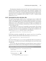
The 3GPP standard and implementation costs of the receiver set basic requirements for a
PIC receiver. The strong channel coding specified in the standard and usually short spreading
factor mean that SINR can be quite low at a receiver, resulting in unreliable tentative
decisions and high BER before decoding, up to 15 %. This means that the hard decision-
based PIC cannot work very well, since for every wrong decision, the corresponding
interference is doubled. SQ-PIC tries to overcome this by using a reliability measure to
weight the tentative decisions as mentioned. In order to minimise costs, only one PIC stage is
suggested as the performance improvement from the second or third stage is not that large.
12.6.2.3 PIC Efficiency and Derivation of Network Level Gains
We define PIC efficiency as the amount of own-cell interference it can remove. (It is
assumed that PIC cannot remove other inter-cell interference.) We can write I
total
for Rake
and PIC as
I
total;rake
¼ I
own
þ iI
own
þ N
0
¼ð1 þ iÞK
rake
P
j
þ P
N
ð12:26aÞ
I
total;PIC
¼ð1 À ÞI
own
þ iI
own
þ N
0
¼ð1 þ i À ÞK
pic
P
j
þ P
N
ð12:26bÞ
where i is the ratio of other-cell interference to own-cell interference, P
N
is the thermal noise
power and we have assumed that users are homogenous, each having the same received
power P
j
. K
rake
and K
pic
are the number of users for Rake and PIC, respectively. K
pic
is
selected so that I
total,rake
and I
total,pic
are equal i.e. noise rises of Rake and PIC are the same.
We can solve capacity gain G
cap
¼ K
pic
/K
rake
from the equations above:
G
cap
¼
K
pic
K
rake
¼
1 þ i
1 þ i À
ð12:27Þ
Coverage gain is defined as the ratio of required E
b
=N
0
s for Rake and PIC when the number
of users, K, is kept constant:
G
cov
¼
E
b
=N
0
fg
rake
E
b
=N
0
fg
pic
ð12:28Þ
Using the definition of E
b
=N
0
and using Equations (12.26) we get:
E
b
=N
0
fg
K
¼
W
R
P
j
P
N
¼
W
R
1
1
L
j
À 1 þ i À ðÞK
ð12:29Þ
Note that is zero for a Rake receiver. From Equations (12.28) and (12.29) we obtain:
G
cov
¼
E
b
=N
0
fg
rake
E
b
=N
0
fg
pic
¼
W
R
1
1
L
j
À 1 þ iðÞK
W
R
1
1
L
j
À 1 þ i À ðÞK
¼
1
L
j
Àð1 þ i À ÞK
1
L
j
Àð1 þ iÞK
ð12:30Þ
We can solve K from the noise rise equation, Equation (8.9):
K ¼
1
L
j
À
1
L
j
ÁI
rake
1 þ i
ð12:31Þ
Physical Layer Performance 403
where Á I
rake
is the noise rise with a Rake receiver. We can now solve G
cov
as a function of i,
and ÁI
rake
:
G
cov
¼ 1 þ
Á ÁI
rake
À 1ðÞ
1 þ i
ð12:32Þ
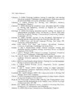
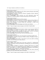
Examples of the capacity gain in Equation (12.27) and the coverage gain in Equation (12.28)
as functions of i are depicted in Figure 12.56 and Figure 12.57. In coverage gain examples,
the noise rise of rake ÁI
rake
is also a parameter. The gains increase as i decreases, which is
0 0.1 0.2 0.3 0.4 0.5 0.6 0.7
0
20
40
60
80
100
120
i
G
cap
(%)
β
= 0.5
β
= 0.4
β
= 0.3
Figure 12.56. Capacity gain of PIC as a function of i with PIC efficiency as a parameter
0 0.1 0.2 0.3 0.4 0.5 0.6 0.7
0
1
2
3
4
I
rake
=
3 dB
G
cov
i
(dB)
6 dB
I
rake
=
β
∆
∆
= 0.5
= 0.4
β
= 0.3
β
Figure 12.57. Coverage gain of PIC as a function of inter-cell interference i, multiuser efficiency
and noise rise ÁI
Rake
404 WCDMA for UMTS
expected since PIC cannot cancel other-cell interference. The gains naturally also depend
on . The dependence is particularly strong in single cell without any other-cell interference,
i ¼ 0. Coverage gain also depends on the target noise rise with a Rake receiver: the higher
the interference level without PIC, the higher the gain from PIC.
12.6.2.4 Performance of SQ-PIC
The performance of SQ-PIC was evaluated by Monte Carlo simulations in the link level
without inter-cell interference [74]. Two propagation channels were considered, namely a
pedestrian type of environment (Case 1 in 3GPP TS 25.141) and a vehicular type of
environment (Case 3 in 3GPP TS 25.141). In the pedestrian channel, the UE velocity was
3 km/h, and in the vehicular channel, 120 km/h. The 12.2 kbps speech and 384 kbps data
services were studied.
We estimate the PIC efficiency from the simulation results by finding the value of that
gives the best fit to the simulation results. The results are shown in Table 12.23. The PIC
efficiency is between 24 % and 41 %. The highest efficiency is obtained at high mobile speed
with high data rate 384 kbps. The fast power control cannot keep the received power level
exactly constant at high speed and there are larger power differences that can be cancelled by
PIC. A high data rate provides better efficiency, since the number of simultaneous users is
lower and the number of estimated parameters by PIC is lower, resulting in more accurate
estimates. With a data service, the small spreading factor results also in high cross
correlation between users, making the performance of Rake poor and hence allowing
higher potential gain for SQ-PIC. The lowest gain is obtained at low mobile speed with voice
users.
Table 12.24 shows capacity and coverage gains with the estimated efficiencies.
The capacity gains are 26–35 % in a typical macro cell with i ¼ 0.55. The coverage gain
is 1.6–2.5 dB. This coverage gain assumes an initial noise rise of 6 dB. If the initial noise rise
was 3 dB, the corresponding coverage gain would be 0.6–1.0 dB.
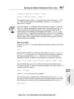
Numerical results for a data service are depicted in Figure 12.58 for channel case 3. The
number of diversity antennas was one, two or four for both Rake and SQ-PIC. Rake with
diversity antennas can be seen as an alternative to PIC, since increasing the order of diversity
also provides substantial gains. The reason for this is Rake’s ability to average MAI over
diversity antennas, as the interference components from different diversity channels are
independent. The results show that increasing the number of antennas with a Rake receiver
Table 12.23. PIC efficiency
PIC efficiency
Number of diversity —————————————————
Propagation channel antennas (M) 384 kbps data 12.2 kbps speech
Case 1 v ¼ 3 km/h 1 32 % 24 %
2 36 % 26 %
4 37 % 33 %
Case 3 v ¼ 120 km/h 1 40 % 35 %
2 41 % 32 %
4 36 % 28 %
Physical Layer Performance 405
provides higher capacity and better coverage than introducing PIC. In the case of a low
number of users, the gain from any interference cancellation is low, while more antennas
provide clear coverage benefits. On the other hand, adding more antennas and antenna cables
may not be possible from the site solution point of view, while the introdu ction of
interference cancellation as the baseband processing enhancement is easier.
Interference cancellation, namely SQ-PIC, is the most promising method for improving
base station receiver performance, as well as system capacity and coverage. Uplink
interference cancellation may provide further gains in end user throughput when the uplink
Table 12.24. Capacity and coverage gains with simulated PIC efficiencies (with outer-to-own cell
interference ratio i ¼ 0.55)
Coverage gain (dB) with
Capacity gain ( %) 6 dB noise rise
——————————— ——————————
384 kbps 12.2 kbps 384 kbps 12.2 kbps
Propagation channel M data speech data speech
Case 1 v ¼ 3 km/h 1 26 % 26 % 2.1 dB 1.6 dB
2 30 % 30 % 2.3 dB 1.8 dB
4 31 % 31 % 2.3 dB 2.1 dB
Case 3 v ¼ 120 km/h 1 35 % 35 % 2.5 dB 2.2 dB
2 36 % 36 % 2.5 dB 2.1 dB
4 30 % 30 % 2.3 dB 1.9 dB
0 5 10 15 20 25 30 35
−5
0
5
10
15
20
1 ant
2 ant
4 ant
Required
E
b
/
N
0
(dB)
K
Rake, sim.
SQ-PIC, sim
Rake, theory
PIC,theory
β
=0.4
β
=0.41
β
=0.36
Figure 12.58. Required E
b
=N
0
vs. number of users for a 384 kbps data service and BLER target 10 %
in case 3 channel (120 km/h), the number of diversity antennas 1, 2 and 4
406 WCDMA for UMTS
peak data rates exceed 1 Mbps in High-Speed Uplink Packet Access, HSUPA, which is a
3GPP study item in Release 6. For more details see Chapter 11.
References
[1] Holma, H., Soldani, D. and Sipila
¨
, K. ‘Simulated and Measured WCDMA Uplink Performance’,
Proceedings VTC 2001 Fall, Atlantic City, NJ, USA, pp. 1148–1152.
[2] UMTS, Selection Procedures for the Choice of Radio Transmission Technologies of the UMTS,
ETSI, v.3.1.0, 1997.
[3] Laiho-Steffens, J. and Lempia
¨
inen, J., ‘Impact of the Mobile Antenna Inclinations on the
Polarisation Diversity Gain in DCS1800 Network’, Proceedings of PIMRC’97, Helsinki, Finland,
September 1997, pp. 580–583.
[4] Lempia
¨
inen, J. and Laiho-Steffens, J., ‘The Performance of Polarisation Diversity Schemes at a
Base-Station in Small/Micro Cells at 1800MHz’, IEEE Trans. Vehic. Tech., Vol. 47, No. 3, August
1998, pp. 1087–1092.
[5] Sorensen, T.B., Nielsen, A.O., Mogensen, P.E., Tolstrup, M. and Steffensen, K., ‘Performance of
Two-Branch Polarisation Antenna Diversity in an Operational GSM Network’, Proceedings of
VTC’98, Ottawa, Canada, 18–21 May 1998, pp. 741–746.
[6] Grandell, J. and Salonaho, O. ‘Macro Cell Measurements with the Nokia WCDMA Experimental
System’, IEE Conference on Antennas and Propagation, UK, 2001, pp. 516–520.
[7] Westman, T. and Holma, H., ‘CDMA System for UMTS High Bit Rate Services’, Proceedings of
VTC’97, Phoenix, AZ, May 1997, pp. 825–829.
[8] Pehkonen, K., Holma, H., Keskitalo, I., Nikula, E. and Westman, T., ‘A Performance Analysis of
TDMA and CDMA Based Air Interface Solutions for UMTS High Bit Rate Services’, Proceedings
of PIMRC’97, Helsinki, Finland, September 1997, pp. 22–26.
[9] Ojanpera
¨
, T. and Prasad, R., Wideband CDMA for Third Generation Mobile Communications,
Artech House, 1998, 439.
[10] Holma, H., ‘A Study of UMTS Terrestrial Radio Access Performance’, Doctoral thesis, Commu-
nications Laboratory, Helsinki University of Technology, Espoo, Finland, 2003.
[11] Sipila, K., Honkasalo, Z.C., Laiho-Steffens, J., Wacker, A. ‘Estimation of Capacity and Required
Transmission Power of WCDMA Downlink Based on a Downlink Pole Equation’, Proceedings of
VTC 2000 Spring., Tokyo, Japan, May 2000, pp. 1002–1005.
[12] 3GPP Technical Specification 25.104 ‘UTRA (BS) FDD; Radio transmission and Reception’.
[13] 3GPP Technical Specification 25.101 ‘UE Radio Transmission and Reception (FDD)’.
[14] Winters, J.H., ‘Smart Antennas for Wireless Systems’, IEEE Personal Communications , Vol. 5,
Issue 1, February 1998, pp. 23–27.
[15] Paulraj, A. and Chong-Ng, B. ‘Space–Time Modems for Wireless Personal Communications’,
IEEE Personal Communications, February 1998, pp. 36–49.
[16] Anderson, S., Hagerman, B., Dam, H., Forssen, U., Karlsson, J., Kronested, F., Mazur, S. and
Molnar, K. ‘Adaptive Antennas for GSM and TDMA Systems’, IEEE Personal Communications,
June 1999, pp. 74–86.
[17] Pedersen, K.I. and Mogensen, P.E. ‘Evaluation of Vector-Rake Receivers Using Different Antenna
Array Configurations and Combining Schemes’, Internal Journal on Wireless Information
Networks, 1999, vol. 6, pp. 181–194.
[18] Osseiran, A., Ericson, M., Barta, J., Goransson, B. and Hagerman, B. ‘Downlink Capacity
Comparison Between Different Smart Antenna Concepts in a Mixed Service WCDMA System’,
IEEE Proc. Vehicular Technology Conference, September 2001, pp. 1528–1532.
[19] Tiirola, E. and Ylitalo, J. ‘Performance Evaluation of Fixed-Beam Beamforming in WCDMA
Downlink’, Proc. Vehicular Technology Conference, Tokyo, Japan, May 2000, pp. 700–704.
[20] Pedersen, K.I., Mogensen, P.E. and Ramiro-Moreno, J. ‘Application and Performance of
Downlink Beamforming Techniques in UMTS’, IEEE Communications Magazine, October
2003, pp. 134–143.
[21] 3GPP Technical Specification 25.215 ‘Physical Layer Measurements’, v.5.4.
Physical Layer Performance 407
[22] Pedersen, K.I. and Mogensen, P.E. ‘Directional Power Based Admission Control for WCDMA
Systems Using Beamforming Antenna Array Systems’, IEEE Trans. on Vehicular Technology,
November 2002, Vol. 51, No. 6, pp. 1294–1303.
[23] Osseiran, A. and Ericson, M. ‘On downlink admission control with fixed multi-beam antennas for
WCDMA systems’, Proc. IEEE Vehicular Technology Conference, VTC-2003-Spring, April 2003,
pp. 1203–1207.
[24] Pedersen, K.I. and Mogensen, P.E. ‘Performance of WCDMA HSDPA in a Beamforming
Environment Under Code Constraints’, Proc. IEEE Vehicular Technology Conference VTC-
2003-fall, October 2003.
[25] Klingenbrunn, T., ‘Downlink Capacity Enhancements of UTRA FDD Networks’, Ph.D. Thesis,
Aalborg University, 2001.
[26] Godara, L.C., ‘Application of Antenna Arrays to Mobile Communications, Part I: Performance
Improvement, Feasibility, and System Considerations’, Proc. IEEE, Vol. 85, No. 7, 1997,
pp. 1031–1060.
[27] Godara, L.C., ‘Application of Antenna Arrays to Mobile Communications, Part II: Beam-
forming and Direction-of-Arrival Considerations’, Proc. IEEE, Vol. 85, No. 8, 1997, pp. 1195–
1245.
[28] Jakes, W.J. (ed.), Microwave Mobile Communications, IEEE Press, New Jersey, 1974.
[29] Muszynski, P., ‘Interference Rejection Rake-Combining for WCDMA’, Proceedings of WPMC’98,
Yokosuka, Japan, November 1998, pp. 93–97.
[30] Winters, J.H., ‘Optimum Combining in Digital Mobile Radio with Co-channel Interference’, IEEE
Trans. Vehic. Tech., Vol. 33, No. 3, 1984, pp. 144–155.
[31] Monzingo, R.A. and Miller, T.W., Introduction to Adaptive Arrays, John Wiley & Sons, New York,
1980.
[32] Pursley, M.B., ‘Performance Evaluation for Phase-Coded Spread-Spectrum Multiple-Access
Communication – Part I: System Analysis’, IEEE Trans. Commun., Vol. 25, No. 8, 1977,
pp. 795–799.
[33] Gilhousen, K.S., Jacobs, I.M., Padovani, R., Viterbi, A.J., Weaver, L.A. and Wheatley III, C. E.,
‘On the Capacity of a Cellular CDMA System’, IEEE Trans. Vehic. Tech., Vol. 40, No. 2, 1991,
pp. 303–312.
[34] Viterbi, A.J., CDMA: Principles of Spread Spectrum Communication, Addison-Wesley Wireless
Communications Series, Addison-Wesley, Reading, MA, 1995.
[35] Proakis, J.G., Digital Communications, 3rd edn, McGraw-Hill, New York, 1995.
[36] Verdu
´
, S., ‘Minimum Probability of Error for Asynchronous Gaussian Multiple-Access Channels’,
IEEE Trans. Inform. Th., Vol. 32, No. 1, 1986, pp. 85–96.
[37] Juntti, M. and Glisic, S., ‘Advanced CDMA for Wireless Communications’, in Wireless
Communications: TDMA Versus CDMA, ed. S. Glisic and P. Leppa
¨
nen, Chapter 4, pp. 447–
490, Kluwer, 1997.
[38] Verdu
´
, S., Multiuser Detection, Cambridge University Press, Cambridge, UK, 1998.
[39] Lupas, R. and Verdu
´
, S., ‘Near–Far Resistance of Multiuser Detectors in Asynchronous Channels’,
IEEE Trans. Commun., Vol. 38, No. 4, 1990, pp. 496–508.
[40] Klein, A. and Baier, P.W., ‘Linear Unbiased Data Estimation in Mobile Radio Systems Applying
CDMA’, IEEE J. Select. Areas Commun., Vol. 12, No. 7, 1999, pp. 1058–1066.
[41] Zvonar, Z., ‘Multiuser Detection in Asynchronous CDMA Frequency-Selective Fading Channels’,
Wireless Personal Communications, Kluwer, Vol. 3, No. 3–4, 1996, pp. 373–392.
[42] Xie, Z., Short, R.T. and Rushforth, C.K., ‘A Family of Suboptimum Detectors for Coherent
Multiuser Communications’, IEEE J. Select. Areas Commun., Vol. 8, No. 4, 1990, pp. 683–
690.
[43] Klein, A., Kaleh, G.K. and Baier, P.W., ‘Zero Forcing and Minimum Mean-Square-Error
Equalization for Multiuser Detection in Code-Division Multiple Access Channels’, IEEE Trans.
Vehic. Tech., Vol. 45, No. 2, 1996, pp. 276–287.
[44] Varanasi, M.K. and Aazhang, B., ‘Multistage Detection in Asynchronous Code-Division Multiple-
Access Communications’, IEEE Trans. Commun., Vol. 38, No. 4, 1990, pp. 509–519.
[45] Kohno, R., Imai, H., Hatori, M. and Pasupathy, S., ‘Combination of an Adaptive Array Antenna and
a Canceller of Interference for Direct-Sequence Spread-Spectrum Multiple-Access System’, IEEE
J. Select. Areas Commun., Vol. 8, No. 4, 1990, pp. 675–682.
408 WCDMA for UMTS
[46] Viterbi, A. J., ‘Very Low Rate Convolutional Codes for Maximum Theoretical Performance of
Spread-Spectrum Multiple-Access Channels’, IEEE J. Select. Areas Commun., Vol. 8, No. 4, 1990,
pp. 641–649.
[47] Patel, P. and Holtzman, J., ‘Analysis of a Simple Successive Interference Cancellation Scheme in a
DS/CDMA System’, IEEE J. Select. Areas Commun., Vol. 12, No. 10, 1994, pp. 796–807.
[48] Madhow, U. and Honig, M.L., ‘MMSE Interference Suppression for Direct-Sequence Spread-
Spectrum CDMA’, IEEE Trans. Commun., Vol. 42, No. 12, 1994, pp. 3178–3188.
[49] Rapajic, P. B. and Vucetic, B. S., ‘Linear Adaptive Transmitter–Receiver Structures for
Asynchronous CDMA Systems’, European Trans. Telecommun., Vol. 6, No. 1, 1995, pp. 21–27.
[50] Miller, S. L., ‘An Adaptive Direct-Sequence Code-Division Multiple-Access Receiver for
Multiuser Interference Rejection’, IEEE Trans. Commun. , Vol. 43, No. 2/3/4, 1995, pp. 1746–1755.
[51] Latva-aho, M., ‘Advanced Receivers for Wideband CDMA Systems’, Vol. C125 of Acta
Universitatis Ouluensis, Doctoral thesis, University of Oulu Press, Oulu, Finland, 1998.
[52] Latva-aho, M. and Juntti, M., ‘Modified LMMSE Receiver for DS-CDMA – Part I: Performance
Analysis and Adaptive Implementations’, Proceedings of ISSSTA’98, Sun City, South Africa,
September 1998, pp. 652–657.
[53] Honig, M., Madhow, U. and Verdu
´
, S., ‘Blind Adaptive Multiuser Detection’, IEEE Trans. Inform.
Th., Vol. 41, No. 3, 1995, pp. 944–960.
[54] Latva-aho, M., ‘LMMSE Receivers for DS-CDMA Systems in Frequency-Selective Fading
Channels’, in CDMA Techniques for 3rd Generation Mobile Systems, ed. F. Swarts, P. van Rooyen,
I. Oppermann and M. Lo
¨
tter, Chapter 13, Kluwer, 1998.
[55] Juntti, M. and Latva-aho, M., ‘Multiuser Receivers for CDMA Systems in Rayleigh Fading
Channels’, IEEE Trans. Vehic. Tech., Vol. 49, No. 3, 2000, pp. 885–889.
[56] Correal, N.S., Swanchara, S.F. and Woerner, B.D., ‘Implementation Issues for Multiuser DS-
CDMA Receivers’, Int. J. Wireless Inform. Networks, Vol. 5, No. 3, 1998, pp. 257–279.
[57] Juntti, M., ‘Multiuser Demodulation for DS-CDMA Systems in Fading Channels’, Vol. C106 of
Acta Universitatis Ouluensis, Doctoral thesis, University of Oulu Press, Oulu, Finland, 1997.
[58] Ojanpera
¨
, T., Prasad, R. and Harada, H., ‘Qualitative Comparison of Some Multiuser
Detector Algorithms for Wideband CDMA’, Proceedings of VTC’98, Ottawa, Canada, May
1998, pp. 46–50.
[59] Ojanpera
¨
, T., ‘Multirate Multiuser Detectors for Wideband CDMA’, Ph.D. thesis, Technical
University of Delft, Delft, The Netherlands, 1999.
[60] Johansson, A L., ‘Successive Interference Cancellation in DS-CDMA Systems’, Doctoral thesis,
Chalmers University of Technology, Go
¨
teborg, Sweden, 1998.
[61] Juntti, M., ‘Multiuser Detector Performance Comparisons in Multirate CDMA Systems’,
Proceedings of VTC’98, Ottawa, Canada, May 1998, pp. 36–40.
[62] Wijting, C.S., Ojanpera
¨
, T., Juntti, M. J., Kansanen, K. and Prasad, R., ‘Groupwise Serial Multiuser
Detectors for Multirate DS-CDMA’, Proceedings of VTC’99, Houston, TX, May 1999, pp. 836–
840.
[63] Juntti, M., ‘Performance of Multiuser Detection in Multirate CDMA Systems’, Wireless Pers.
Commun., Kluwer, Vol. 11, No. 3, 1999, pp. 293–311.
[64] Werner, S. and Lillberg, J., ‘Downlink Channel Decorrelation in CDMA Systems with Long
Codes’, Proceedings of VTC’99, Houston, TX, May 1999, pp. 836–840.
[65] Hooli, K., Latva-aho, M. and Juntti, M., ‘Multiple Access Interference Suppression with Linear
Chip Equalizers in WCDMA Downlink Receivers’, Proceedings of Globecom’99, Rio de Janeiro,
Brazil, December 1999, pp. 467–471.
[66] Hooli, K., Juntti, M. and Latva-aho, M., ‘Performance Evaluation of Adaptive Chip-Level Channel
Equalizers in {WCDMA} Downlink’, Proceedings of ICC’01, Helsinki, Finland, June 2001, pp.
1974–1979.
[67] Komulainen, P. and Heikkila
¨
, M., ‘Adaptive Channel Equalization Based on Chip Separation for
CDMA Downlink’, Proceedings of PIMRC’99, Osaka, Japan, September 1999, pp. 1114–1118.
[68] Hooli, K. ‘Equalization in WCDMA Terminals’. Doctoral thesis. Acta Universitatis Ouluensis C
192, University of Oulu Press, Oulu, Finland, 2003.
[69] Grant, P.M., Spangenberg, S.M., Cruickshank, G.M., McLaughlin, S. and Mulgrew, B., ‘New
Adaptive Multiuser Detection Technique for CDMA Mobile Receivers’, Proceedings of
PIMRC’99, Osaka, Japan, September 1999, pp. 52–54.
Physical Layer Performance 409
[70] Divsalar, D. and Simon, M. K., ‘Improved CDMA performance using parallel interference
cancellation’, Proc. IEEE MILCOM’94, Fort Monmouth, N. J. USA, Oct. 2–5, 1994, pp. 911–917.
[71] Cho, Bong Youl and Lee, Jae Hong, ‘Nonlinear parallel interference cancellation with partial
cancellation for a DS-CDMA system’, IEICE Trans. On Communications, Vol. E83-B, September
2000.
[72] Bae, J., Song, I. and Won, D. H., ‘A selective and adaptive interference cancellation scheme for
code division multiple access systems’, Signal Processing, Vol. 83, No. 2, February 2003, Elsevier
Science B.V.
[73] Divsalar, D., Simon, M.K., and Raphaeli, D., ‘Improved Parallel Interference Cancellation for
CDMA’, IEEE Trans. Commun., Vol. 46, No. 2, February 1998, pp. 258–268.
[74] Vihria
¨
la
¨
, J. and Horneman, K., ‘Impacts of SQ-PIC to Capacity and Coverage in WCDMA Uplink’,
to appear in ISSSTA’04, September 2004.
410 WCDMA for UMTS
13
UTRA TDD Modes
Antti Toskala, Harri Holma, Otto Lehtinen and Heli Va
¨
a
¨
ta
¨
ja
¨
13.1 Introduction
The UTRA TDD modes are intended to operate in the unpaired spectrum, as shown in
Figure 1.2 in Chapter 1, illustrating the spectrum allocations in various regions. As can be
seen from Figure 1.2, there is no TDD spectrum available in all regions. The background of
UTRA TDD was described in Chapter 4. During the standardisation process in ETSI and
3GPP, the major parameters were harmonised between UTRA FDD and TDD modes,
including chip rate of 3.84 Mcps and modulation, for the Release ’99 specifications. During
the Release 4 work, the low chip rate TDD with 1.28 Mcps (TD-SCDMA) was introduced,
following the same principles as the 3.84 Mcps TDD but with a few additional features, such
as uplink synchronisation, as well as the mandatory differences arising from the different
chip rate. Both TDD modes are covered in the physical layer specifications for the 3rd
Generation Partnership Project (3GPP), the documents TS 25.221–TS 25.224 and TS 25.102
[1–5] are especially valuable references for obtaining information on the exact details. For
Release 5, the High-Speed Downlink Packet Access (HSDPA) presented for FDD in Chapter 11
has been included for TDD as well. The TDD operation of HSDPA includes similar ARQ
operation, use of 16 QAM modulation and fast Node B based scheduling, as described in
Chapter 11.
This chapter first introduces TDD as a duplex method on a general level. The physical
layer and related procedures of the UTRA TDD modes are introduced in Section 13.2.
UTRA TDD interference issues are evaluated in Section 13.3. The HSDPA operation
principles with TDD modes are covered in Section 13.4.
13.1.1 Time Division Duplex (TDD)
Three different duplex transmission methods are used in telecommunications: frequency
division duplex (FDD), time division duplex (TDD) and space division duplex (SDD). The
FDD method is the most common duplex method in the cellular systems. It is used, for
example, in GSM, as well as with the WCDMA terminals currently com merciallly deployed
in the UMTS frequency bands. The FDD method requires separate frequency bands for both
WCDMA for UMTS, third edition. Edited by Harri Holma and Antti Toskala
# 2004 John Wiley & Sons, Ltd ISBN: 0-470-87096-6
uplink and downlink. The TDD method uses the same frequency band but alternates the
transmission direction in time. TDD is used, for example, for the digital enhanced cordless
telephone (DECT). The SDD method is used in fixed-point transmission where directive
antennas can be used. It is not used in cellular terminals, however, the use of beamforming
techniques with FDD or TDD can be considered an SDD application as well .
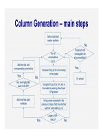
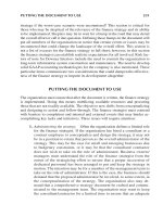
Figure 13.1 illustrates the operating principles of the FDD and TDD methods. The term
downlink or forward link refers to transmission from the base station (fixed network side) to
the mobile terminal (user equipment), and the term uplink or reverse link refers to
transmission from the mobile terminal to the base station.
There are some characteristics peculiar to the TDD system and these are listed below.
Utilisation of unpaired band. The TDD system can be implemented on an unpaired
band while the FDD system always requires a pair of bands.
Discontinuous transmission. Switching between transmission directions requires time,
and the switching transients must be controlled. To avoid corrupted transmission, the
uplink and downlink transmissions require a common means of agreein g on transmission
direction and allowed time to transmit. Corruption of transmission is avoided by
allocating a guard period which allows uncorrupted propagation to counter the propaga-
tion delay. Discontinuous transmission may also cause audible interference to audio
equipment that does not comply with electromagnetic susceptibility requirements.
Interference between uplink and downlink. Since uplink and downlink share the same
frequency band, the signals in these two transmission directions can interfere with each
other. In FDD, this interference is completely avoided by the duplex separation of
190 MHz. In UTRA TDD, individual base stations need to be synchr onised to each other
at frame level to avoid this interference. This interference is further analysed in Section 13.3.
Asymmetric uplink/downlink capacity allocation. In TDD operation, uplink and
downlink are divided in the time domain. It is possible to change the duplex switching
point and move capacity from uplink to downlink, or vice versa, depending on the
capacity requirement between uplink and downlink.
Reciprocal channel. The fast fading depends on the frequency, and therefore, in FDD
systems, the fast fading is uncorrelated between uplink and downlink. As the same
Bandwidth 5 MHz Bandwidth 5 MHz Bandwidth 5 MHz
FDD TDD
Uplink
Uplink
Downlink
Downlink
t
Guard
period
t
Duplex separation
190 MHz
ff
Figure 13.1. Principles of FDD and TDD operation
412 WCDMA for UMTS
frequency is used for both uplink and downlink in TDD, the fast fading is the same in
uplink and in downlink. Based on the received signal, the TDD transceiver can estimate
the fast fading, which will affect its transmission. Knowledge of the fast fading can be
utilised in power control and in adaptive antenna techniques in TDD.
13.1.2 Differences in the Network Level Architecture
The UTRA TDD differs from the FDD mode operation for those issues that are related to the
different Layer 1. The protocols have been devised with the principle that there are typically
common messages, but the information elements are specific for the mode (FDD or TDD)
being used. The use of the Iur interface is not needed for soft handover purposes with TDD,
as only one Node B is transmitting for one user. If the TDD system uses relocation, then
there is no need to transfer user data over the Iur interface at all in practice. Figure 13.2
illustrates the key differences for TDD compared to the architecture in Chapter 5. The core
network does not typically see any difference, except that some of the highest data rate
capabilities are not likely to be available, depending on the sum of the uplink and downlink
data rates being used. From the RNC point of view, the biggest issue to cope with is the radio
resource management (RRM), which in TDD is based on different measurements and
resource allocation principles, along with the use of dynamic channel allocation (DCA).
13.2 UTRA TDD Physical Layer
The UTRA TDD mode uses a combined time division and code division multiple access
(TD/CDMA) scheme that adds a CDMA component to a TDMA system. The different user
signals are separat ed in both time and code domains. Table 13.1 presents a summary of the
UTRA physi cal layer parameters. All the major RF parameters are harmonised within
Figure 13.2. TDD differences to FDD from the network architecture point of view
UTRA TDD Modes 413
UTRA for FDD and 3.84 Mcps TDD mode, with 1.28 Mcps TDD, the resulting RF
parameters are obviously different due to the different bandwidth.
13.2.1 Transport and Physical Channels
UTRA TDD mode transport channels can be divided into dedicated and common channels.
Dedicated channels (DCH) are characterised in basically the same way as in the FDD mode.
Common channels can be further divided into common control channels (CCCH), the
random access channel (RACH), the downlink shared channel (DSCH) in the downlink, and
the uplink shared channel (USCH) in the uplink. Each of these transport channels is then
mapped to the corresponding physical channel.
The physical channels of UTRA TDD are the dedicated physical channel (DPCH),
common control physical channel (CCPCH), physical random access channel (PRACH),
paging indicator channel (PICH) and synchronisation channel (SCH). For the SCH and
PICH there do not exist corresponding transport channels. The mapping of the different
transport channels to the physical channels and all the way to the bursts is shown in
Table 13.1. Comparison of UTRA FDD and TDD physical layer key parameters (Release 4)
UTRA TDD UTRA FDD
Multiple access method TDMA, CDMA
(inherent FDMA)
CDMA (inherent FDMA)
Duplex method TDD FDD
Channel spacing (nominal) 5 MHz/1.66 MHz 5 MHz
Carrier chip rate 3.84 Mcps/1.28 Mcps 3.84 Mcps
Time slot structure 15/14 slots/frame 15 slots/frame
Frame length 10 ms
Multirate concept Multicode, multislot and
orthogonal variable spreading
factor (OVSF)
Multicode and OVSF
Forward error correction
(FEC) codes
Convolutional coding R ¼
1
2
or 1/3, constraint length K ¼ 9, turbo
coding (8-state PCCC R ¼ 1=3) or service-specific coding
Interleaving Inter-frame interleaving (10, 20, 40 and 80 ms)
Modulation QPSK/8PSK QPSK
Burst types Three types: traffic
bursts, random access and
synchronisation burst
Not applicable
Detection Coherent, based on midamble Coherent, based on pilot
symbols
Dedicated channel power
control
Uplink: open loop; 100 Hz or
200 Hz
Fast closed loop;
rate ¼ 1500 Hz
Downlink: closed loop;
rate 800 Hz
Intra-frequency handover Hard handover Soft handover
Inter-frequency handover Hard handover
Channel allocation DCA supported No DCA required
Intra-cell interference
cancellation
Support for joint detection Support for advanced
receivers at base station
Spreading factors 1 16 4 512
414 WCDMA for UMTS
Figure 13.3. The physical channel structure is discussed in the following section in more
detail.
13.2.2 Modulation and Spreading
The data modulation scheme in UTRA TDD is QPSK, addi tionally, 8PSK was added in the
1.28 Mcps TDD to enable the theoretical 2 Mbps peak rate to be reached. The modulated
data symbols are spread with a specific channelisation code of length 1–16. The modulated
and spread data is finally scrambled by a pseudorandom sequence of length 16. The same
type of orthogonal channelisation codes are used in the UTRA FDD system (see Section 6.3).
Data spreading is followed by scrambling with a cell- or source-specific scrambling
sequence; the scrambling process is chip -by-chip multiplication. The combination of
multiplying with channelisation code and the cell-specific scrambling code is a user- or
cell-specific spreading procedure. Final ly, pulse shape filtering is applied to each chip at the
transmitter: each chip is filtered with a root raised cosine filter with roll-off factor ¼ 0.22,
identical to UTRA FDD.
13.2.3 Physical Channel Structures, Slot and Frame Format
The physical frame structure is similar to that of the UTRA FDD mode. The frame length
is 10 ms and it has two different forms, depending on the chip rate. The 3.84 Mcps TDD
Transport
channels
Physical
channels
Higher layers
Dedicated channel (DCH)
Common channels
Common control physical channel
(CCPCH)
Dedicated
physical channel
(DPCH)
Bursts
Traffic burst I/II
Random access
channel (RACH)
Physical Random
access channel
(PRACH)
Common control
channels (CCCH)
Broadcast channel
(BCH)
Paging channel
(PCH)
Forward access
channel (FACH)
Uplink shared channel
(USCH)
Downlink shared channel
(DSCH)
Shared
channels
Physical USCH
Physical DSCH
Random access
burst
Figure 13.3. Mapping of the Release 4 UTRA TDD transport channels to physical channels
UTRA TDD Modes 415
frame is divided into 15 time slots, each of 2560 chips, i.e., the time slot duration is 666 ms.
Figure 13.4 shows the frame structure for 3.84 Mcps TDD.
Each of the 15 time slots within a 10 ms frame is allocated to either uplink or downlink.
Multiple switching points for different transmission directions per frame allow closed loop
power control and a physical synchronisation channel (PSCH) in dedicated downlink slots to
speed cell search. On the other hand, to be able to cover dynamic asymmetric services, the
flexibility in slot allocation in the downlink/uplink direction guarantees efficient use of the
spectrum. To maintain maximum flexibility while allowing closed loop power control
whenever useful, the SCH has two time slots per frame for downlink transmission. The
PSCH is mapped to two downlink slots.
For the 1.28 Mcps TDD the 15 slots principle was not chosen, as the resulting number of
chips is not evenly divisible by 15. Instead, 14 slots was decided upon for the frame content.
These 14 slots are divided into 5 ms sub-frames as indicated in Figure 13.5.
Code 1
Code 2
Code
N
TS0 TS1 TS2 TS3 TS4 TS5 TS6 TS7 TS8 TS9 TS10 TS11 TS12 TS13 TS14
MA
10 ms
Figure 13.4. Frame structure of UTRA TDD. The number of code channels that may be used within a
single time slot varies depending on the propagation conditions (MA ¼ midamble)
Data symbols
352 chips
Data symbols
352 chips
Midamble
144 chips
Guard period
16 chips
Time slot = 864 chips
Slot #0 Slot #1
Slot #4 Slot #6
Sub-frame = 5 ms = 6400 chips
Frame #0 Frame #1
frame = 10 ms
Slot #5Slot #3
Slot #2
Uplink/downlink pilots and main guard period
Figure 13.5. 1.28 Mcps TDD frame, sub-frame and downlink slot structure
416 WCDMA for UMTS
Since the TDMA transmission in UTRA TDD is discontinuous, the average transmission
power is reduced by a factor of 10 Â log
10
(n/15), where n is the number of active time slots
per frame. For example, to provide the same coverage with UTRA TDD using a single time
slot for 144 kbps requires at least four times more base station sites than with UTRA FDD.
This 12 dB reduction in the average power would result in a typical macro cell environment
to reduce the cell range more than into half, and thus, the cell area to a quarter. When
utilising the same hardware in the UE, the TDMA discontinuous transmission with low duty
cycle leads to reduced uplink range. With higher data rates the coverage difference to FDD
reduces. Due to these properties, TDD should be used in small cell environments where
power is not a limiting factor and data rates used for the coverage planning are higher.
13.2.3.1 Burst Types
There are three bursts defined for UTRA TDD. All of them are used for dedicated channels
while common channels typically use only a subset of them.
Burst types I and II are usable for both upli nk and downlink directions with the difference
between the type I and II being the midamble length. Figure 13.6 illustrates the general
downlink, and Figure 13.7 the uplink burst structure with transmission power control (TPC)
and transmission format combination indicator (TFCI).
The burst types with two variants of midamble length can be used for all services up to
2 Mbps. The logical traffic channel (TCH), which contains user data, is mapped to a burst.
Additionally, for the 1.28 Mcps TDD there is physical layer control information added in the
downlink to support the uplink synchronisation procedure.
The data fields are separated by a midamble which is used for channel estimation. The
transport format combination indicator (TFCI) is used to indicate the combination of used
transport channels in the dedicated physical channel (DPCH) and is sent only once per
frame. The TFCI uses in-band signalling and has its own coding. The number of TFCI bits is
variable and is set at the beginning of the call.
For the uplink burst in Figure 13.7, both transmission power control (TPC) and TFCI are
present. Both TFCI and TPC are transmitted in the same physical channel and use in-band
signalling. The length of the TPC command is one symbol.
The burst contains two data fields separated by a midamble and followed by a guard
period. The duration of a burst is one time slot. The midamble is used for both channel
Data symbols
TFCI
Midamble Data symbols
Guard
period
2560*
T
c
TFCI
Figure 13.6. Generalised UTRA TDD downlink burst structure
Data symbols
TFCI
TFCI
TPC
Midamble Data symbols
Guard
period
2560*
T
c
Figure 13.7. Generalised uplink burst structure
UTRA TDD Modes 417
equalisation and coherent detection at the receiver. The midamble reduces the user data
payload. Table 13.2 shows the burst type I and II structures in detail.
Due to the longer midamble, burst type I is applicable for estimating 16 different uplink
channel impulse responses. Burst type II can be used for the downlink independently of the
number of active users. If there are fewer than four users within a time slot, burst type II can
also be used for the uplink.
For the 1.28 Mcps the different burst types offer typically from 32 to 44 bits per data field,
depending on the use of TPC or synchronisation. The smaller numb er of chips and resulting
payload comes directly from the relationship of the chip rates between the different modes,
though some of the overheads take a relatively larger amount in 1.28 Mcps TDD. Also, the
use of uplink synchronisation requires additional bits for physical layer signalling in
1.28 Mcps TDD.
The midambles, i.e. the training sequences of different users, are time-shifted versions of
one periodic basic code. Different cells use different periodic basic codes, i.e. different
midamble sets. Due to the generation of midambles from the same periodic basic code,
channel estimation of all active users within one time slot can be performed jointly, for
example by one single cyclic correlator. Channel impulse response estimates of different
users are obtained sequentially in time at the output of the correlator [6].
The downlink uses either a spreading factor of 16 with the possibility of multicode
transmission, or a spreadi ng factor of 1 for high bit rate applications in case such a capability
is supported by the terminals. In the uplink, orthogonal variable spreading factor (OVSF)
codes with spreading factors from 1 to 16 are used. The total number of the burst formats is
20 in the downlink and 90 in the upli nk.
The burst type III is used in the uplink direction only. This has developed for the needs for
the PRACH, as well as to facilitate handover in cases when timing advance is needed. The
guard time of 192 chips (50 ms) equals a cell radius of 7.5 km.
13.2.3.2 Physical Random Access Channel (PRACH)
The logical random access channel (RACH) is map ped to a physical random access
(PRACH) channel. Table 13.2 shows the burst type III used with PRACH, and Figure 13.8
illustrates the burst type III structure. Spreading factor values of 16 and 8 are used for
PRACH. With PRACH there are typically no TPC or TFCI bits used, as shown in Figure 13.8.
Table 13.2. Burst type field structures for 3.84 Mcps TDD
Data field 1 Training Data field 2 Guard period
Burst name length sequence length length length
Burst type I 976 chips 512 chips 976 chips 96 chips
Burst type II 1104 chips 256 chips 1104 chips 96 chips
Burst type III 976 chips 512 chips 880 chips 192 chips
Data symbols
Midamble Data symbols
Guard
period
2560*
T
c
Figure 13.8. UTRA TDD burst type III when used with PRACH
418 WCDMA for UMTS
13.2.3.3 Synchronisation Channel (SCH)
The time division duplex creates some special needs for the synchronisation channel. A
capturing problem arises due to the cell synchronisation, i.e. a phenomenon occurring when
a stronger signal masks weaker signals. The time misalignment of the different synchronisa-
tion channels of different cells would allow for distinguishing several cells within a single
time slot. For this reason a variable time offset (t
offset
) is allocated between the SCH and the
system slot timing. The offset between two consecutive shifts is 71T
c
. There exist two
different SCH structures. The SCH can be mapped either to the slot number k 2f0 14g or
to time slots k and k þ 8, k 2f0 6g. Figure 13.9 shows the latter SCH structure for k ¼ 0.
This dual-SCH-per-frame structure is intended for cellular use. The position of the SCH can
vary on a long-term basis.
The terminal can acquire synchronisation and the coding scheme for the BCCH of the cell
in one step and will be able to detect cell messaging instantl y. The primary (c
p
) and the three
secondary (c
s
) synchron isation sequences are transmitted simultaneously. Codes are 256
chips long as in the UTRA FDD mode, and the primary code is generated in the same way as
in the FDD mode, as a generalised hierarchical Golay sequence. The secondary synchro-
nisation code words (c
s
) are chosen from every 16th row of the Hadamard sequence H
8
,
which is used also in the FDD mode. By doing this there are only 16 possible code words, in
comparison to 32 of the FDD mode. The codes are QPSK modulated and the following
information is indicated by the SCH:
Base station code group out of 32 possible alternatives (5 bits);
Position of the frame in the interleaving period (1 bit);
Slot position in the frame (1 bit);
Primary CCPCH locations (3 bits).
TS 0 TS 1 TS 2 TS 3 TS 4 TS 5 TS 6 TS 7 TS 8 TS 9 TS10 TS11 TS12 TS13 TS14
C
p
C
0
s
C
1
s
C
2
s
Downlink
Uplink
1 frame = 10 ms = 15 time slots
1 time slot = 2560
T
c
t
offset
666 us
Figure 13.9. UTRA TDD SCH structure. This example has two downlink slots allocated for SCH
(k ¼ 0). The primary code (c
p
) and three QPSK-modulated secondary codes (c
s
) are transmitted
simultaneously. The time offset (t
offset
) is introduced to avoid adverse capture effects of the
synchronous system. The combined transmission power of the three c
s
is equal to the power of c
p
UTRA TDD Modes 419
With a sequence it is possible to decode the frame synchronisation, the time offset (t
offset
),
the midamble and the spreading code set of the base station, as well as the spreading code(s)
and location of the broadcast channel (BCCH).
The cell parameters within each code group are cycled over two frames to randomise
interference between base stations and to enhance system performance. Also, network
planning becomes easier with the averaging property of the parameter cycling.
In the 1.28 Mcps TDD, the downlink pilots, as indicated in Figure 13.10, contain
the necessary synchronisation information. The Downlink Pilot Channel (DwPCH) is
transmitted in each 5 ms sub-frame over the whole coverage area, in a similar way to the
SCH in the 3.84 Mcps TDD. The pattern used on the 64 chips of information can have 32
different downlink synchronisation codes.
13.2.3.4 Common Control Physical Channel (CCPCH)
Once the synchronisation has been acquired, the timing and coding of the primary broadcast
channel (BCH) are known. The CCPCH can be mapped to any downlink slot(s), including
the PSCH slots, and this is indicated by the primary BCH.
The CCPCH is similar to the downlink dedicated physical channel (DPCH). It may be
coded with more redundancy than the other channels to simplify acquisition of in formation.
13.2.3.5 UTRA TDD Shared Channels
The UTRA TDD specification also defines the Downlink Shared Channel (DSCH) and the
Uplink Shared Channel (USCH). These channels use exactly the same slot structure as do
the dedicated channels. The difference is that they are allocated on a temporary basis.
In the downlink, the signalling to indicate which terminals need to decode the channel can
be done with TFCI, by detecting midamble in use or by higher layers. In the uplink, the
USCH uses higher layer signalling and thus is not shared in practice on a frame-by-frame
basis.
13.2.3.6 User Data Rates
Table 13.3 shows the UTRA TDD user bit rates with
1
2
-rate channel coding and spreading
factor 16. The tail bits, TFCI, TPC or CRC overhead have not been taken into account.
Spreading factors other than 16 (from the orthogonal variable spreading scheme) can be seen
Figure 13.10. The 1.28 Mcps TDD sub-frame pilot structure
420 WCDMA for UMTS
as subsets of spreading factor 16 (i.e. spreading factor 8 in the uplink corresponds to two
parallel codes with spreading factor 16 in the downlink). When the number of needed slots
exceeds seven, the corresponding data rate can be provided only for either the uplink or the
downlink. The bit rates shown in Table 13.3 are time slot and code limited bit rates,
the maximum interference limited bit rate can be lower. The 1.28 Mcps TDD resulting data
rate is around 8 kbps with one slot per sub-frame (two slots per 10 ms), spreading factor 16
and the use of QPSK. There are 69 different uplink formats with QPSK and 24 different
downlink formats that can be used to build a particular data rate.
13.2.4 UTRA TDD Physical Layer Procedures
13.2.4.1 Power Control
The purpose of power control is to minimise the interference of separate radio links. Both the
uplink and downlink dedicated physical channels (DPCH) and physical random access
channel (PRACH) are power controlled. The forward access channel (FACH) may be power
controlled. The implementation of advanced receivers, such as the joint detector, will
suppress intra-cell (own-cell) interference and reduce the need for fast power control. The
optimum multiuser detector is near–far resistant [7] but in practice the limited dynamic
range of the sub-optimum detector restricts performance. Table 13.4 shows the 3.84 Mcps
UTRA TDD power control characteristics and Table 13.5 shows the 1.28 Mcps TDD power
control characteristics.
In the downlink, closed loop is used after initial transmission. The reciprocity of the
channel is used for open loop power control in the uplink. Based on interference level at the
Table 13.3. UTRA TDD 3.84 Mcps air interface user bit rates
Number of allocated timeslots
Number of allocated codes with
spreading factor 16 1 4 13
1 13.8 kbps 55.2 kbps 179 kbps
8 110 kbps 441 kbps 1.43 Mbps
16 (or spreading factor 1) 220 kbps 883 kbps 2.87 Mbps
Table 13.4. Power control characteristics of 3.84 Mcps UTRA TDD
Uplink Downlink
Method Open loop SIR-based closed inner loop
Dynamic range 65 dB
Minimum power À44 dBm or
less
Maximum power 21 dBm
30 dB (all the users are within 20 dB in
one time slot)
Step size 1, 2, 3 dB 1, 2, 3 dB
Rate Variable
1–7 slots delay (2-slot PCCPCH)
1–14 slots delay (1-slot PCCPCH)
From 100 Hz to approximately 750 Hz
UTRA TDD Modes 421
base station and on path loss measurements of the downlink, the mobile weights the path loss
measurements and sets the transmission power. The interference level and base station
transmitter power are broadcast. The transmitter power of the mobile is calculated by the
following equation [4]:
P
UE
¼ L
PCCPCH
þð1 À ÞL
0
þ I
BTS
þ SIR
TARGET
þ C ð13:1Þ
In Equation (13.1) P
UE
is the transmitter power level in dBm, L
PCCPCH
is the measured path
loss in dB, L
0
is the long-term average of path loss in dB, I
BTS
is the interference signal
power level at the base station receiver in dBm, and is a weighting parameter which
represents the quality of path loss measurements. is a function of the time delay between
the uplink time slot and the most recent downlink PCCPCH time slot. SIR
TARGET
is the target
SNR in dB; this can be adjusted through higher layer outer loop. C is a constant value.
13.2.4.2 Data Detection
UTRA TDD requires that simultaneously active spreading codes within a time slot are
separated by advanced data detection techniques. The usage of conventional detectors, i.e.
matched filters or Rake, in the base station requires tight uplink power control, which is
difficult to implement in a TDD system since the uplink is not continuously available. Thus,
advanced data detection techniques should be used to suppress the effect of power
differences between users, i.e. the near–far effect. Both inter-symbol interference (ISI)
due to multipath propagation and multiple access interference (MAI) between data symbols
of different users are present also in downlink. In downlink, the intra-cell interference is
suppressed by the orthogo nal codes, and the need for advanced detectors is lower than in
uplink. In UTRA TDD the number of simultaneously active users is small and the use of
relatively short scrambling codes, together with spreading, make the use of advanced
receivers attractive.
The sub-optimal data detection techniques can be categorised as single user detectors
and multiuser detectors (see Section 12.5.2). In UTRA TDD, single user detectors can
be applied when all signals pass through the same propagation channel, i.e. they are primarily
applied for the downlink [8]. Otherwise, multiuser or joint detection is applied [9, 10].
Single user detectors first equalise the received data burst to remove the distortion caused
by the channel. When perfect equalisation is assumed, the orthogonality of the codes is
restored after equalisation. The desired signal can now be separated by code-matched
filtering. The advantages of using single user detectors are that no knowledge of the other
user’s active codes is required and the computational complexity is low compared to joint
detection [8].
Table 13.5. 1.28 Mcps TDD power control characteristics
Uplink Downlink
Method Initially open loop and then SIR-based inner loop
(for some control channel only open loop)
SIR-based inner loop
Rate Closed loop: 0-200 Hz 0–200 Hz
Open loop: variable delay depending on slot
allocation
Closed loop step sizes 1,2,3 dB 1,2,3 dB
422 WCDMA for UMTS
To be able to combat both MAI and ISI in UTRA TDD, equalisation based on, for
example, zero-forcing (ZF) or minimum mean-square-error (MMSE) can be applied. Both
equalisation methods can be applied with or without decision feedback (DF). The
computational complexity of the algorithms is essential ly the same, but the performance
of the MMSE equalisers is better than that of the ZF equalisers [10]. The decision feedback
option improves performance (about 3 dB less E
b
=N
0
at practical bit error rates) and the
MMSE algorithm generally performs better (less than 1 dB difference in E
b
=N
0
require-
ments) than zero-forcing. Antenna diversity techniques can be applied with joint detection
[11, 12] to further enhance the performance.
The performance of Rake, ZF equaliser, MMSE equaliser and HD-PIC (hard decision
parallel interference canceller [13]) in the UTRA TDD uplink was studied using Monte
Carlo computer simulations in the UTRA TDD uplink [14]. Eight users with spreading factor
of 16 occupy one time slot within a 10 ms frame. A two-path channel with tap gains of 0 dB
and À9.7 dB, and with a mobile speed of 3 km/h is considered. Channel estimation and
power control are assumed to be ideal and channel coding is omitted. The performance of
Rake, ZF, MMSE, and one- and two-stage HD-PIC are shown in Figure 13.11. The results
show that the advanced base station receivers give a clear gain compared to the Rake
receiver in UTRA TDD, even with ideal power control. As the signal-to-noise ratio (SNR)
increases, the performance of ZF and MMSE is better than the performance of HD-PIC.
Channel coding typically increases the differences between the performance of different
detectors. For example, in the operational area of BER ¼ 5–10 % the gain from the advanced
receiver structures can be up to 2 dB with perfect power control and even more with realistic
power control. The difference between the presented advanced detectors is small in this
operational area.
Indoor channel, 3 km/h, perfect PC, 8 users, 16 SF
0 2 4 6 8 10 12
SNR (dB)
BER
10
−3
10
−2
10
−1
10
0
Rake
ZF
MMSE
1-stage HD-PIC
2-stage HD-PIC
Figure 13.11. Performance of Rake, ZF and MMSE equalisers and one- and two-stage HD-PIC in the
3.84 Mcps UTRA TDD uplink
UTRA TDD Modes 423
13.2.4.3 Timing Advance
To avoid interference between consecutive time slots in large cells, it is possible to use a
timing advancement scheme to align the separate transmission instants in the base station
receiver. The timing advance is determined by a 6-bit number with an accuracy of four
chips (1.042 ms). The base station measures the required timing advance, and the terminal
adjusts the transmission according to higher layer messaging. The maximum cell range
is 9.2 km.
The UTRA TDD cell radius without timing advance can be calculated from the guard
period of traffic burst (96 chips ¼ 25 ms), resulting in a range of 3.75 km. This value exceeds
practical TDD cell ranges (micro and pico cells) and in practice the timing advance is not
likely to be needed.
13.2.4.4 Channel Allocation in TDD
In order to offer continuous coverage, a TDD system needs to use Dynamic Channel
Allocation (DCA) to cope with the interference at the cell borders with reuse 1 and with the
lack of soft handover. The 3GPP specifications define the RNC-controlled DCA signalling,
which offers the possibility of slow DCA based on the Node B and UE measurements of the
interference conditions in different time slots.
The measurement reports are passed always to the SRNC, thus, for practical operation,
SRNC needs to be the same as CRNC, which is secured by means of relocation. In Release 6,
additional procedures are being worked on that could enable the relaying of the measure-
ment from the SRNC to CRNC, which removes the requirement for relocation, but on the
other hand makes the DCA operation at RNC level still slower.
The fast DCA in general, referred to in earlier editions of this book as Node B terminated
DCA, does not exist in practice in Release ’99 or Release 4. The HSDPA in Release 5 can be
considered as being limited fast DCA between HSDPA users but it does not modify, e,g, the
uplink and downlink slot resource allocation or allocation to CS domain services.
13.2.4.5 Handover
UTRA TDD supports inter-system handovers and intra-system handovers (to UTRA FDD
and to GSM). All these handovers are mobile-assisted hard handovers.
UTRA TDD does not use soft handover (or macro diversity). This is a clear difference
from UTRA FDD, in which the protocol structure has been designed to support soft
handover. The UTRA TDD protocol structure has followed the same architecture as FDD for
termination points for maximum commonality above the physical layer. This means, for
example, that handover protocols terminate at the same location (RNC) but consist of FDD
and TDD mode-specific parameters.
13.2.4.6 UTRA TDD Transmit Diversity
UTRA TDD supports four downlink transmit diversity methods. They are comparable to
those in UTRA FDD. For dedicated physical channels Switched Transmitter Diversity (STD)
and Transmit Adaptive Antennas (TxAA) methods are supported. The antenna weights are
calculated using the reciprocity of the radio link. In order to utilise the TxAA method, the
required base station receiver and transmitter chain calibration makes the implementation
more challenging.
For common channels, Time Switched Transmit Diversity (TSTD) is used for PSCH, and
Block Space Time Transmit Diversity (Block STTD) is used for primary CCPCH.
424 WCDMA for UMTS
For uplink at the base station, the same receiver diversity methods as in FDD are
applicable to enhance the performance.
13.2.4.7 1.28 Mcps TDD-specific Physical Layer Procedures
The 1.28 Mcps TDD contains some chip rate-specific refinements to the physical layer
procedures arising from differences in the physical layer structure. Procedures like power
control have differences due to the use of sub-frame division, which results in different
command rates. Th ere is also a fully 1.28 Mcps-specific procedure, as, instead of timing
advance, uplink synchronisation is used to try to reduce uplink interference. The principle is
to have users in the uplink sharing the same scrambling code and to have uplink transmission
partly orthogonal by coordinating the uplink TX timing with closed loop control and small
(1/5–1/8 chip) resolution. Different resolutions are allowed in order not to force the use of
any particular sampling rate in the terminal.
13.3 UTRA TDD Interference Evaluation
In this section we evaluate the effect of interference within the TDD band and between TDD
and FDD. TDD–TDD interference is analysed in Section 13.3.1 and the co-existence of
TDD and FDD systems in Section 13.3.2.
13.3.1 TDD–TDD Interference
Since both uplink and downlink share the same freq uency in TDD, these two transm ission
directions can interfere with each other. By nature the TDD system is synchronous and this
kind of interference occurs if the base stations are not synchronised. It is also present if
different asymmetry is used between the uplink and downlink in adjacent cells even if the
base stations are frame synchronised. Frame synchronisation requires an accuracy of a few
symbols, not an accuracy of chips. The guard period allows more tolerance in synchronisa-
tion requirements. Figure 13.12 illustrates possible interference scenarios. The interference
within the TDD band is analysed with system simulations in [15].
Interference between uplink and downlink can also occur between adjacent carriers.
Therefore, it can also take place between two operators.
In FDD operation, the duplex separation prevents interference between uplink and
downlink. The interference between a mobile and a base station is the same in both TDD
and FDD operation and is not considered in this chapter.
BS
1
BS
2
MS
2
MS
1
Figure 13.12. Interference between mobiles, between base stations, and between mobile
and base station
UTRA TDD Modes 425
13.3.1.1 Mobile Station to Mobile Station Interference
Mobile-to-mobile interference occurs if mobile MS
2
in Figure 13.12 is transmitting and
mobile MS
1
is receiving simultaneously in the same (or adjacent) frequency in adjacent
cells. This type of interference is statistical because the locations of the mobiles cannot be
controlled. Therefore, it cannot be avoided by network planning. Intra-operator mobile-to-
mobile interference occurs especially at cell bo rders. Inter-operator interference between
mobiles can occur anywhere where two operators’ mobiles are close to each other and
transmitting on fairly high power. Methods to counter mobile-to-mobile interference are:
DCA and radio resource management;
Power control.
13.3.1.2 Base Station to Base Station Interference
Base station to base station interference occurs if base station BS
1
in Figure 13.12 is
transmitting and base station BS
2
is receiving in the same (or adjacent) frequency in adjacent
cells. It depends heavily on the path loss between the two base stations and therefore can be
controlled by network planning.
Intra-operator interference between base stations depends on the base station locations.
Interference between base stations can be especially strong if the path loss is low between
the base stations. Such cases could occur, for example, in a macro cell, if the base stations
are located on masts above rooftops. The best way to avoid this interference is by careful
planning to provide sufficient coupling loss between base stations.
The outage probabiliti es in [15] show that cooperation between TDD operators in network
planning is required, or the networks need to be synchronised and the same asymmetry needs
to be applied. Sharing base station sites between operators will be very problematic, if not
impossible. The situation would change if operators had inter-network synchronisation and
identical uplink/downlink splits in their systems.
From the synchronisation and coordination point of view, the higher the transmission
power levels and the larger the intended coverage area, the more difficult will be the
coordination for interference management. In particular, the locations of antennas of the
macro cell type tend to result in line-of-sight connections between base stations, causing
strong interference. Ope rating TDD in indoor and micro/pico cell environments will mean
lower power levels and will reduce the problems illustrated.
13.3.2 TDD and FDD Co-existence
The UTRA FDD and TDD have spectrum allocations that meet at the border at 1920 MHz,
and therefore TDD and FDD deployment cannot be considered independently: see
Figure 13.13. The regional allocations were shown in Figure 1.2 in Chapter 1. Dynamic
channel allocation (DCA) can be used to avoid TDD–TDD interference, but DCA is not
effective between TDD and FDD, since FDD has continuous transmission and reception.
The possible interference scenarios between TDD and FDD are summarised in Figure 13.14.
13.3.2.1 Co-siting of UTRA FDD and TDD Base Stations
From the network deployment perspective, the co-siting of FDD and TDD base stations
looks an interesting alternative. There are, however, problems due to the close proximity of
the frequency bands. The lower TDD band, 1900–1920 MHz, is located adjacent to the FDD
426 WCDMA for UMTS
uplink band, 1920–1980 MHz. The resulting filtering requirements in TDD base stations
are expected to be such that co-siting a TDD base station in the 1900–1920 MHz band with
an FDD base station is not considered technically and commercially a viable soluti on.
Table 13.6 illustrates the situation. The output power of 24 dBm corresponds to a small pico
base station and 43 dBm to a macro cell base station.
UMTS/
TDD2
UMTS/FDD UL
20252010198019201900
Interference between lower TDD
band and FDD uplink band
MHz
Satellite
UMTS/
TDD1
Figure 13.13. Interference between lower TDD band and FDD uplink band
UTRA / FDD
UTRA / FDD
UTRA / TDD
UTRA / TDD
Co-siting
interference
section
13.3.2.1
Section
13.3.2.3
Section
13.3.2.2
Section
13.3.2.4
Figure 13.14. Possible interference situations between lower TDD band and FDD uplink band
Table 13.6. Coupling loss analysis between TDD and FDD base stations in adjacent frequencies
at 1920 MHz
TDD base station output power (pico/macro) 24/43 dBm
Adjacent channel power ratio À45 dBc
Isolation between antennas (separate antennas for FDD and TDD base stations) À30 dB
Leakage power into FDD base station receiver À51/–32 dBm
Allowed leakage power À110 dBm
Required attenuation 59/78 dB
UTRA TDD Modes 427