802.11® Wireless Networks: The Definitive Guide phần 4 pot
Bạn đang xem bản rút gọn của tài liệu. Xem và tải ngay bản đầy đủ của tài liệu tại đây (383.66 KB, 43 trang )
frame with WEP. The header identifying the frame as an authentication frame is
preserved, but the information elements are hidden by WEP.
After receiving the third frame, the access point attempts to decrypt it and verify the WEP
integrity check. If the frame decrypts to the Challenge Text, and the integrity check is
verified, the access point will respond with a status code of successful. Successful
decryption of the challenge text proves that the mobile station has been configured with
the WEP key for the network and should be granted access. If any problems occur, the
access point returns an unsuccessful status code.
7.3.3 Preauthentication
Stations must authenticate with an access point before associating with it, but nothing in
802.11 requires that authentication take place immediately before association. Stations
can authenticate with several access points during the scanning process so that when
association is required, the station is already authenticated. This is called
preauthentication. As a result of preauthentication, stations can reassociate with access
points immediately upon moving into their coverage area, rather than having to wait for
the authentication exchange.
In both parts of Figure 7-6, there is an extended service set composed of two access
points. Only one mobile station is shown for simplicity. Assume the mobile station starts
off associated with AP1 at the left side of the diagram because it was powered on in
AP1's coverage area. As the mobile station moves towards the right, it must eventually
associate with AP2 as it leaves AP1's coverage area.
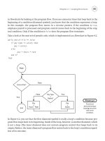
Figure 7-6. Time savings of preauthentication
Preauthentication is not used in the most literal interpretation of 802.11, shown in Figure
7-6a. As the mobile station moves to the right, the signal from AP1 weakens. The station
continues monitoring Beacon frames corresponding to its ESS, and will eventually note
the existence of AP2. At some point, the station may choose to disassociate from AP1,
and then authenticate and reassociate with AP2. These steps are identified in the figure, in
which the numbers are the time values from Table 7-1.
Table 7-1. Chronology for Figure 7-6
Step
Action without preauthentication
(Figure 7-6a)
Action with preauthentication (Figure 7-
6b)
0 Station is associated with AP1 Station is associated with AP1
1
Station moves right into the overlap
between BSS1 and BSS2
Station moves right into the overlap between
BSS1 and BSS2 and detects the presence of
AP2
1.5
Station preauthenticates to AP2
2
AP2's signal is stronger, so station
decides to move association to AP2
AP2's signal is stronger, so station decides to
move association to AP2
3 Station authenticates to AP2 Station begins using the network
4 Station reassociates with AP2
5 Station begins using the network
Figure 7-6b shows what happens when the station is capable of preauthentication. With
this minor software modification, the station can authenticate to AP2 as soon as it is
detected. As the station is leaving AP1's coverage area, it is authenticated with both AP1
and AP2. The time savings become apparent when the station leaves the coverage area of
AP1: it can immediately reassociate with AP2 because it is already authenticated.
Preauthentication makes roaming a smoother operation because authentication can take
place before it is needed to support an association. All the steps in Figure 7-6b are
identified by time values from Table 7-1.Proprietary Authentication Approaches
The shared-key authentication method has its drawbacks. It is stronger than open-system
authentication with address filtering, but it inherits all of WEP's security weaknesses. In
response, some vendors have developed proprietary public-key authentication algorithms,
many of which are based on 802.1x. Some of these proprietary approaches may serve as
the basis for future standards work.
7.4 Association
Once authentication has completed, stations can associate with an access point (or
reassociate with a new access point) to gain full access to the network. Association is a
recordkeeping procedure that allows the distribution system to track the location of each
mobile station, so frames destined for the mobile station can be forwarded to the correct
access point. After association completes, an access point must register the mobile station
on the network so frames for the mobile station are delivered to the access point. One
method of registering is to send a gratuitous ARP so the station's MAC address is
associated with the switch port connected to the access point.
Association is restricted to infrastructure networks and is logically equivalent to plugging
into a wired network. Once the procedure is complete, a wireless station can use the
distribution system to reach out to the world, and the world can respond through the
distribution system. 802.11 explicitly forbids associating with more than one access
point.
7.4.1 Association Procedure
The basic association procedure is shown in Figure 7-7.
Figure 7-7. Association procedure
Like authentication, association is initiated by the mobile station. No sequence numbers
are needed because the association process is a three-step exchange. The two frames are
management frame subtypes defined by the specification. As unicast management
frames, both steps in the association procedure are composed of an association frame and
the required link-layer acknowledgment:
1. Once a mobile station has authenticated to an access point, it can issue an
Association Request frame. Stations that have not yet authenticated receive a
Deauthentication frame from the access point in response.
2. The access point then processes the association request. 802.11 does not specify
how to determine whether an association should be granted; it is specific to the
access point implementation. One common consideration is the amount of space
required for frame buffering. Rough estimates are possible based on the Listen
Interval in the Association Request frame.
a. When the association request is granted, the access point responds with a
status code of 0 (successful) and the Association ID (AID). The AID is a
numerical identifier used to logically identify the mobile station to which
buffered frames need to be delivered. More detail on the process can be
found in Section 7.5 of this chapter.
b. Unsuccessful association requests include only a status code, and the
procedure ends.
3. The access point begins processing frames for the mobile station. In all commonly
used products, the distribution system medium is Ethernet. When an access point
receives a frame destined for an associated mobile station, that frame can be
bridged from the Ethernet to the wireless medium or buffered if the mobile station
is in a power-saving state. In shared Ethernets, the frame will be sent to all the
access points and will be bridged by the correct one. In switched Ethernets, the
station's MAC address will be associated with a particular switch port. That
switch port is, of course, connected to the access point currently providing service
for the station.
7.4.2 Reassociation Procedure
Reassociation is the process of moving an association from an old access point to a new
one. Over the air, it is almost the same as an association; on the backbone network,
however, access points may interact with each other to move frames. When a station
moves from the coverage area of one access point to another, it uses the reassociation
process to inform the 802.11 network of its new location. The procedure is shown in
Figure 7-8.
Figure 7-8. Reassociation procedure
The mobile station begins the procedure associated with an access point. The station
monitors the quality of the signal it receives from that access point, as well as the signal
quality from other access points in the same ESS. When the mobile station detects that
another access point would be a better choice, it initiates the reassociation procedure. The
factors used to make that decision are product-dependent. Received signal strength can be
used on a frame-by-frame basis, and the constant Beacon transmissions provide a good
baseline for signal strength from an access point. Before the first step, the mobile station
must authenticate to the new access point if it has not done so already.
Figure 7-8 depicts the following steps:
1. The mobile station issues a Reassociation Request to the new access point.
Reassociation Requests have content similar to Association Requests. The only
difference is that Reassociation Request frames contain a field with the address of
the old access point. The new access point must communicate with the old access
point to determine that a previous association did exist. The content of the inter-
access point messages is proprietary, though the 802.11 working group is in the
process of standardizing the inter-access point protocol. If the new access point
cannot verify that the old access point authenticated the station, the new access
point responds with a Deauthentication frame and ends the procedure.
2. The access point processes the Reassociation Request. Processing Reassociation
Requests is similar to processing Association Requests; the same factors may be
used in deciding whether to allow the reassociation:
a. If the Reassociation Request is granted, the access point responds with a
Status Code of 0 (successful) and the AID.
b. Unsuccessful Reassociation Requests include just a Status Code, and the
procedure ends.
3. The new access point contacts the old access point to finish the reassociation
procedure. This communication is part of the IAPP.
4. The old access point sends any buffered frames for the mobile station to the new
access point. 802.11 does not specify the communication between access points;
filling in this omission is one of the major standardization efforts in the 802.11
working group. At the conclusion of the buffered frame transfer:
a. Any frames buffered at the old access point are transferred to the new
access point so they can be delivered to the mobile station.
b. The old access point terminates its association with the mobile station.
Mobile stations are allowed to associate with only one access point at any
given time.
5. The new access point begins processing frames for the mobile station. When it
receives a frame destined for the mobile station, that frame is bridged from the
Ethernet to the wireless medium or buffered for a mobile station in a power-
saving mode.
Reassociation is also used to rejoin a network if the station leaves the coverage area and
returns later to the same access point. Figure 7-9 illustrates this scenario.
Figure 7-9. Reassociation with the same access point
7.5 Power Conservation
The major advantage of wireless networks is that network access does not require nodes
to be in any particular location. To take full advantage of mobility, nothing can constrain
the location of a node, including the availability of electrical power. Mobility therefore
implies that most mobile devices can run on batteries. But battery power is a scarce
resource; batteries can run only so long before they need to be recharged. Requiring
mobile users to return frequently to commercial power is inconvenient, to say the least.
Many wireless applications require long battery life without sacrificing network
connectivity.
As with any other network interface, powering down the transceiver can lead to great
power savings in wireless networks. When the transceiver is off, it is said to be sleeping,
dozing, or in power-saving mode (PS). When the transceiver is on, it is said to be awake,
active, or simply on. Power conservation in 802.11 is achieved by minimizing the time
spent in the latter stage and maximizing the time in the former. However, 802.11
accomplishes this without sacrificing connectivity.
7.5.1 Power Management in Infrastructure Networks
Power management can achieve the greatest savings in infrastructure networks. All traffic
for mobile stations must go through access points, so they are an ideal location to buffer
traffic. There is no need to work on a distributed buffer system that must be implemented
on every station; the bulk of the work is left to the access point. By definition, access
points are aware of the location of mobile stations, and a mobile station can communicate
its power management state to its access point. Furthermore, access points must remain
active at all times; it is assumed that they have access to continuous power. Combining
these two facts allows access points to play a key role in power management on
infrastructure networks.
Access points have two power management-related tasks. First, because an access point
knows the power management state of every station that has associated with it, it can
determine whether a frame should be delivered to the wireless network because the
station is active or buffered because the station is asleep. But buffering frames alone does
not enable mobile stations to pick up the data waiting for them. An access point's second
task is to announce periodically which stations have frames waiting for them. The
periodic announcement of buffer status also helps to contribute to the power savings in
infrastructure networks. Powering up a receiver to listen to the buffer status requires far
less power than periodically transmitting polling frames. Stations only need to power up
the transmitter to transmit polling frames after being informed that there is a reason to
expend the energy.
Power management is designed around the needs of the battery-powered mobile stations.
Mobile stations can sleep for extended periods to avoid using the wireless network
interface. Part of the association request is the Listen Interval parameter, which is the
number of Beacon periods for which the mobile station may choose to sleep. Longer
listen intervals require more buffer space on the access point; therefore, the Listen
Interval is one of the key parameters used in estimating the resources required to support
an association. The Listen Interval is a contract with the access point. In agreeing to
buffer any frames while the mobile station is sleeping, the access point agrees to wait for
at least the listen interval before discarding frames. If a mobile station fails to check for
waiting frames after each listen interval, they may be discarded without notification.
7.5.1.1 Unicast frame buffering and delivery using the Traffic Indication Map (TIM)
When frames are buffered, the destination node's AID provides the logical link between
the frame and its destination. Each AID is logically connected to frames buffered for the
mobile station that is assigned that AID. Multicast and broadcast frames are buffered and
linked to an AID of zero. Delivery of buffered multicast and broadcast frames is treated
in the next section.
Buffering is only half the battle. If stations never pick up their buffered frames, saving
the frames is a rather pointless exercise. To inform stations that frames are buffered,
access points periodically assemble a traffic indication map (TIM) and transmit it in
Beacon frames. The TIM is a virtual bitmap composed of 2,008 bits; offsets are used so
that the access point needs to transmit only a small portion of the virtual bitmap. This
conserves network capacity when only a few stations have buffered data. Each bit in the
TIM corresponds to a particular AID; setting the bit indicates that the access point has
buffered unicast frames for the station with the AID corresponding to the bit position.
Mobile stations must wake up and enter the active mode to listen for Beacon frames to
receive the TIM. By examining the TIM, a station can determine if the access point has
buffered traffic on its behalf. To retrieve buffered frames, mobile stations use PS-Poll
Control frames. When multiple stations have buffered frames, all stations with buffered
data must use the random backoff algorithm before transmitting the PS-Poll.
Each PS-Poll frame is used to retrieve one buffered frame. That frame must be positively
acknowledged before it is removed from the buffer. Positive acknowledgment is required
to keep a second, retried PS-Poll from acting as an implicit acknowledgment. Figure 7-10
illustrates the process.
Figure 7-10. PS-Poll frame retrieval
If multiple frames are buffered for a mobile station, then the More Data bit in the Frame
Control field is set to 1. Mobile stations can then issue additional PS-Poll requests to the
access point until the More Data bit is set to 0, though no time constraint is imposed by
the standard.
After transmitting the PS-Poll, a mobile station must remain awake until either the
polling transaction has concluded or the bit corresponding to its AID is no longer set in
the TIM. The reason for the first case is obvious: the mobile station has successfully
polled the access point; part of that transaction was a notification that the mobile station
will be returning to a sleeping mode. The second case allows the mobile station to return
to a power conservation mode if the access point discards the buffered frame. Once all
the traffic buffered for a station is delivered or discarded, the station can resume sleeping.
The buffering and delivery process is illustrated in Figure 7-11, which shows the medium
as it appears to an access point and two associated power-saving stations. The hash marks
on the timeline represent the beacon interval. Every beacon interval, the access point
transmits a Beacon frame with a TIM information element. (This figure is somewhat
simplified. A special kind of TIM is used to deliver multicast traffic; it will be described
in the next section.) Station 1 has a listen interval of 2, so it must wake up to receive
every other TIM, while station 2 has a listen interval of 3, so it wakes up to process every
third TIM. The lines above the station base lines indicate the ramp-up process of the
receiver to listen for the TIM.
Figure 7-11. Buffered frame retrieval process
At the first beacon interval, there are frames buffered for station 1. No frames are
buffered for station 2, though, so it can immediately return to sleep. At the second beacon
interval, the TIM indicates that there are buffered frames for stations 1 and 2, though only
station 1 woke up to listen to the TIM. Station 1 issues a PS-Poll and receives the frame
in response. At the conclusion of the exchange, station 1 returns to sleep. Both stations
are asleep during the third beacon. At the fourth beacon, both wake up to listen to the
TIM, which indicates that there are frames buffered for both. Both station 1 and station 2
prepare to transmit PS-Poll frames after the expiration of a contention window
countdown as described in Chapter 3. Station 1 wins because its random delay was
shorter. Station 1 issues a PS-Poll and receives its buffered frame in response. During the
transmission, station 2 defers. If, at the end of that frame transmission, a third station,
which is not illustrated, seizes the medium for transmission, station 2 must continue to
stay awake until the next TIM. If the access point has run out of buffer space and has
discarded the buffered frame for station 2, the TIM at the fifth beacon indicates that no
frames are buffered, and station 2 can finally return to a low-power mode.
Stations may switch from a power conservation mode to active mode at any time. It is
common for laptop computers to operate with full power to all peripherals when
connected to AC power and conserve power only when using the battery. If a mobile
station switches to the active mode from a sleeping mode, frames can be transmitted
without waiting for a PS-Poll. PS-Poll frames indicate that a power-saving mobile station
has temporarily switched to an active mode and is ready to receive a buffered frame. By
definition, active stations have transceivers operating continuously. After a switch to
active mode, the access point can assume that the receiver is operational, even without
receiving explicit notification to that effect.
Access points must retain frames long enough for mobile stations to pick them up, but
buffer memory is a finite resource. 802.11 mandates that access points use an aging
function to determine when buffered frames are old enough to be discarded. The standard
leaves a great deal to the discretion of the developer because it specifies only one
constraint. Mobile stations depend on access points to buffer traffic for at least the listen
interval specified with the association, and the standard forbids the aging function from
discarding frames before the listen interval has elapsed. Beyond that, however, there is a
great deal of latitude for vendors to develop different buffer management routines.
7.5.1.2 Delivering multicast and broadcast frames: the Delivery TIM (DTIM)
Frames with a group address cannot be delivered using a polling algorithm because they
are, by definition, addressed to a group. Therefore, 802.11 incorporates a mechanism for
buffering and delivering broadcast and multicast frames. Buffering is identical to the
unicast case, except that frames are buffered whenever any station associated with the
access point is sleeping. Buffered broadcast and multicast frames are saved using AID 0.
Access points indicate whether any broadcast or multicast frames are buffered by setting
the first bit in the TIM to 0; this bit corresponds to AID 0.
Each BSS has a parameter called the DTIM Period. TIMs are transmitted with every
Beacon. At a fixed number of Beacon intervals, a special type of TIM, a Delivery Traffic
Indication Map (DTIM), is sent. The TIM element in Beacon frames contains a counter
that counts down to the next DTIM; this counter is zero in a DTIM frame. Buffered
broadcast and multicast traffic is transmitted after a DTIM Beacon. Multiple buffered
frames are transmitted in sequence; the More Data bit in the Frame Control field indicates
that more frames must be transmitted. Normal channel acquisition rules apply to the
transmission of buffered frames. The access point may choose to defer the processing of
incoming PS-Poll frames until the frames in the broadcast and multicast transmission
buffers have been transmitted.
Figure 7-12 shows an access point and one associated station. The DTIM interval of the
access point is set to 3, so every third TIM is a DTIM. Station 1 is operating in a sleep
mode with a listen interval of 3. It will wake up on every third beacon to receive buffered
broadcast and multicast frames. After a DTIM frame is transmitted, the buffered
broadcast and multicast frames are transmitted, followed by any PS-Poll exchanges with
associated stations. At the second beacon interval, only broadcast and multicast frames
are present in the buffer, and they are transmitted to the BSS. At the fifth beacon interval,
a frame has also been buffered for station 1. It can monitor the map in the DTIM and
send a PS-Poll after the transmission of buffered broadcast and multicast frames has
concluded.
Figure 7-12. Multicast and broadcast buffer transmission after DTIMs
To receive broadcast and multicast frames, a mobile station must be awake for DTIM
transmissions. Nothing in the specification, however, keeps power-saving stations in
infrastructure networks from waking up to listen to DTIM frames. Some products that
implement power-saving modes will attempt to align their awakenings with DTIM
transmissions. If the system administrator determines that battery life is more important
than receiving broadcast and multicast frames, a station can be configured to sleep for its
listen period without regard to DTIM transmissions. Some documentation may refer to
this as extremely low power, ultra power-saving mode, deep sleep, or something similar.
Several products allow configuration of the DTIM interval. Lengthening the DTIM
interval allows mobile stations to sleep for longer periods and maximizes battery life at
the expense of timely delivery. Shorter DTIM intervals emphasize quick delivery at the
expense of more frequent power-up and power-down cycles. You can use a longer DTIM
when battery life is at a premium and delivery of broadcast and multicast frames is not
important. Whether this is appropriate depends on the applications you are using and how
they react to long link-layer delays.
7.5.2 IBSS Power Management
Power management in an IBSS is not as efficient as power management in an
infrastructure network. In an IBSS, far more of the burden is placed on the sender to
ensure that the receiver is active. Receivers must also be more available and cannot sleep
for the same lengths of time as in infrastructure networks.
As in infrastructure networks, power management in independent networks is based on
traffic indication messages. Independent networks must use a distributed system because
there is no logical central coordinator. Stations in an independent network use
announcement traffic indication messages (ATIMs), which are sometimes called ad hoc
traffic indication messages, to preempt other stations from sleeping. All stations in an
IBSS listen for ATIM frames during specified periods after Beacon transmissions.
If a station has buffered data for another station, it can send an ATIM frame as
notification. In effect, the ATIM frame is a message to keep the transceiver on because
there is pending data. Stations that do not receive ATIM frames are free to conserve
power. In Figure 7-13a, station A has buffered a frame for station C, so it sends a unicast
ATIM frame to station C during the ATIM transmission window, which has the effect of
notifying station C that it should not enter power-saving mode. Station B, however, is
free to power down its wireless interface. Figure 7-13b shows a multicast ATIM frame in
use. This frame can be used to notify an entire group of stations to avoid entering low-
power modes.
Figure 7-13. ATIM usage
A time window called the ATIM window follows the Beacon transmission. This window
is the period during which nodes must remain active. No stations are permitted to power
down their wireless interfaces during the ATIM window. It starts at the time when the
beacon is expected and ends after a period specified when the IBSS is created. If the
beacon is delayed due to a traffic overrun, the usable portion of the ATIM window
shrinks by the same amount.
The ATIM window is the only IBSS-specific parameter required to create an IBSS.
Setting it to 0 avoids using any power management. Figure 7-14 illustrates the ATIM
window and its relation to the beacon interval. In the figure, the fourth beacon is delayed
due to a busy medium. The ATIM window remains constant, starting at the target beacon
interval and extending the length of the ATIM window. Of course, the usable period of
the ATIM window shrinks by the length of the delay in beacon transmission.
Figure 7-14. ATIM window
To monitor the entire ATIM window, stations must wake up before the target beacon
transmission. Four situations are possible: the station has transmitted an ATIM, received
an ATIM, neither transmitted nor received, or both transmitted and received. Stations that
transmit ATIM frames must not sleep. Transmitting an ATIM indicates an intent to
transmit buffered traffic and thus an intent to stay active. Stations to which ATIM frames
are addressed must also avoid sleeping so they can receive any frames transmitted by the
ATIM's sender. If a station both transmits and receives ATIM frames, it stays up. A
station is permitted to sleep only if it neither transmits nor receives an ATIM. When a
station stays up due to ATIM traffic, it remains active until the conclusion of the next
ATIM window, as shown in Figure 7-15. In the figure, the station goes active for the first
ATIM window. If it does not send or receive any ATIM frames, it sleeps at the end of the
ATIM window. If it sends or receives an ATIM frame, as in the second ATIM window,
the station stays active until the conclusion of the third ATIM window.
Figure 7-15. ATIM effects on power-saving modes
Only certain control and management frames can be transmitted during the ATIM
window: Beacons, RTS, CTS, ACK, and, of course, ATIM frames. Transmission takes
place according to the rules of the DCF. ATIM frames may be transmitted only during
the ATIM window because stations may be sleeping outside the ATIM window. Sending
an ATIM frame is useless if other stations in the IBSS are sleeping. In the same vein,
acknowledgments are required for unicast ATIM frames because that is the only
guarantee that the ATIM was received and that the frame destination will be active for
the remainder of the beacon interval. Acknowledgments are not required for multicast
ATIM frames because multicast frames cannot be efficiently acknowledged by a large
group of stations. If all potential recipients of an ATIM frame were required to
acknowledge it, the mass of acknowledgments could potentially interrupt network
service.
Buffered broadcast and multicast frames are transmitted after the conclusion of the ATIM
window, subject to DCF constraints. Following the transmission of broadcast and
multicast frames, a station may attempt to transmit unicast frames that were announced
with an ATIM and for which an acknowledgment was received. Following all
transmissions announced with an ATIM, stations may transmit unbuffered frames to
other stations that are known to be active. Stations are active if they have transmitted the
Beacon, an ATIM, or are not capable of sleeping. If contention is severe enough to
prevent a station from sending the buffered frame it announced with an ATIM, the station
must reannounce the transmission with an ATIM at the start of the next ATIM window.
Figure 7-16 illustrates several of these rules. In the first beacon interval, the first station
transmits a multicast ATIM to stations 2, 3, and 4. Multicast ATIM frames need not be
acknowledged, but the transmission of the ATIM means that all stations must remain
active for the duration of the first beacon window to receive multicast frames from station
1. When the ATIM window ends, station 1 can transmit its multicast frame to the other
three stations. After doing so, station 4 can take advantage of the remaining time before
the beacon to transmit a frame to station 1. It was not cleared with an ATIM, but it is
known to be active.
Figure 7-16. Effect of ATIM on power-saving modes in an IBSS network
In the second beacon interval, stations 2 and 3 have both buffered a frame for station 4,
so each transmits an ATIM. Station 4 acknowledges both. At the conclusion of the ATIM
window, station 1 has neither transmitted nor received an ATIM and can enter a low-
power state until the next beacon interval. However, station 2's frame is extremely long
and robs station 3 of the opportunity to transmit its frame.
Station 3 still has a buffered frame for station 4 when the third beacon interval opens. It
therefore retransmits its ATIM frame to station 4, which is acknowledged. Station 2 is not
involved in any ATIM exchanges and can enter a low-power state when the ATIM
window ends. At that time, no broadcast or multicast frames have been buffered, and the
ATIM-cleared frame from station 3 to station 4 can be transmitted. After the frame from
3 to 4 is transmitted, station 4 can again take advantage of the remaining time before the
beacon frame to transmit a frame of its own to station 3, which is known to be active
because of the ATIM exchange.
Stations are responsible for maintaining sufficient memory to buffer frames, but the
buffer size must be traded off against the use of that memory for other purposes. The
standard allows a station in an independent network to discard frames that have been
buffered for an "excessive" amount of time, but the algorithm used to make that
determination is beyond the scope of the standard. The only requirement placed on any
buffer management function is that it retain frames for at least one beacon period.
7.6 Timer Synchronization
Like other wireless network technologies, 802.11 depends a great deal on the distribution
of timing information to all the nodes. It is especially important in frequency-hopping
networks because all stations on the network must change frequency channels in a
coordinated pattern. Timing information is also used by the medium reservation
mechanisms.
In addition to local station timing, each station in a basic service area maintains a copy of
the timing synchronization function (TSF), which is a local timer synchronized with the
TSF of every other station in the basic service area. The TSF is based on a 1-MHz clock
and "ticks" in microseconds. Beacon frames are used to periodically announce the value
of the TSF to other stations in the network. The "now" in a timestamp is when the first bit
of the timestamp hits the PHY for transmission.
7.6.1 Infrastructure Timing Synchronization
The ease of power management in an infrastructure network is based on the use of access
points as central coordinators for data distribution and power management functions.
Timing in infrastructure networks is quite similar. Access points are responsible for
maintaining the TSF time, and any stations associated with an access point must simply
accept the access point's TSF as valid.
When access points prepare to transmit a Beacon frame, the access point timer is copied
into the Beacon's timestamp field. Stations associated with an access point accept the
timing value in any received Beacons, but they may add a small offset to the received
timing value to account for local processing by the antenna and transceiver. Associated
stations maintain local TSF timers so they can miss a Beacon frame and still remain
roughly synchronized with the global TSF. The wireless medium is expected to be noisy,
and Beacon frames are unacknowledged. Therefore, missing a Beacon here and there is
to be expected, and the local TSF timer mitigates against the occasional loss of Beacon
frames.
To assist active scanning stations in matching parameters with the BSS, timing values are
also distributed in Probe Response frames. When a station finds a network by scanning, it
saves the timestamp from the Beacon or Probe Response and the value of the local timer
when it was received. To match the local timer to the network timer, a station then takes
the timestamp in the received network advertisement and adds the number of
microseconds since it was received. Figure 7-17 illustrates this process.
Figure 7-17. Matching the local timer to a network timer
7.6.2 IBSS Timing Synchronization
IBSSs lack a central coordination point, so the Beacon process is distributed. TSF
maintenance is a subset of the Beacon generation process. Time is divided into segments
equivalent to the interbeacon timing period. Beacon frames are supposed to be
transmitted exactly as the beacon interval ends, at the so-called target Beacon
transmission time (TBTT). Independent networks take the TBTT as a guideline.
All stations in the IBSS prepare to transmit a Beacon frame at the target time. As it
approaches, all other traffic is suspended. Timers for the transmission of frames other
than Beacon frames or ATIM frames are stopped and held to clear the medium for the
important management traffic. All stations in the IBSS generate a backoff timer for
Beacon transmission; the backoff timer is a random delay between 0 and twice the
minimum contention window for the medium. After the target beacon interval, all
stations begin to count the Beacon backoff timer down to 0. If a Beacon is received
before the station's transmission time, the pending Beacon transmission is canceled.
In Figure 7-18, each station selects a random delay; station 2 has randomly generated the
shortest delay. When station 2's timer expires, it transmits a Beacon, which is received by
stations 1 and 3. Both stations 1 and 3 cancel their Beacon transmissions as a result.
Because timer synchronization ensures that all stations have synchronized timers,
multiple Beacon frames do not pose a problem. Receivers simply process multiple
Beacon frames and perform multiple updates to the TSF timer.
Figure 7-18. Distributed Beacon generation
Beacon generation interacts closely with power management. Beacon frames must be
generated during the active period around each Beacon interval so that all stations are
available to process the Beacon. Furthermore, the Beacon sender is not allowed to enter a
low-power state until the end of the next active period. The latter rule ensures that at least
one station is awake and can respond to probes from new stations scanning to discover
networks.
Rules for adopting the received timestamp are more complex in an independent network.
No centralized timer exists, so the goal of the standard is to synchronize all timers to the
timer of the fastest-running clock in the BSS. When a Beacon is received, the timestamp
is adjusted for processing delays and compared to the local TSF. The received timestamp
updates the local timer only if it is later than the local timer.
Chapter 8. Contention-Free Service with the
PCF
To support applications that require near real-time service, the 802.11 standard includes a
second coordination function to provide a different way of accessing the wireless
medium. The point coordination function (PCF) allows an 802.11 network to provide an
enforced "fair" access to the medium. In some ways, access to the medium under the PCF
resembles token-based medium access control schemes, with the access point holding the
token. This chapter describes medium access under the PCF, detailed frame diagrams for
the PCF frames, and how power management operations interact with the PCF.
The PCF has not been widely implemented. This chapter is included for two reasons.
Readers interested in the standard itself may also be interested in how the PCF works. It
is also possible that products based on the PCF may someday hit the market, in which
case, network engineers will need to understand the PCF so they can implement it. But
most readers can skip this chapter safely.
8.1 Contention-Free Access Using the PCF
If contention-free delivery is required, the PCF may be used. The PCF is an optional part
of the 802.11 specification; products are not required to implement it. However, the IEEE
designed the PCF so stations that implement only the distributed coordination function
(DCF) will interoperate with point coordinators.
Contention-free service is not provided full-time. Periods of contention-free service
arbitrated by the point coordinator alternate with the standard DCF-based service. The
relative size of the contention-free period can be configured. 802.11 describes the
contention-free periods as providing "near isochronous" services because the contention-
free periods will not always start at the expected time, as described in Section 8.1.3.
Contention-free service uses a centralized access control method. Access to the medium
is restricted by the point coordinator, a specialized function implemented in access points.
Associated stations can transmit data only when they are allowed to do so by the point
coordinator. In some ways, contention-free access under the PCF resembles token-based
networking protocols, with the point coordinator's polling taking the place of a token.
Fundamentals of the 802.11 model remain in place, however. Although access is under
the control of a central entity, all transmissions must be acknowledged.
8.1.1 PCF Operation
Figure 8-1 shows a transfer using the PCF. When the PCF is used, time on the medium is
divided into the contention-free period (CFP) and the contention period. Access to the
medium in the former case is controlled by the PCF, while access to the medium in the
latter case is controlled by the DCF and the rules from Chapter 7. The contention period
must be long enough for the transfer of at least one maximum-size frame and its
associated acknowledgment. Alternating periods of contention-free service and
contention-based service repeat at regular intervals, which are called the contention-free
repetition interval.
Figure 8-1. Using the PCF
8.1.1.1 Reserving the medium during the contention-free period
At the beginning of the contention-free period, the access point transmits a Beacon frame.
One component of the beacon announcement is the maximum duration of the contention-
free period, CFPMaxDuration. All stations receiving the Beacon set the NAV to the
maximum duration to lock out DCF-based access to the wireless medium.
As an additional safeguard to prevent interference, all contention-free transmissions are
separated only by the short interframe space and the PCF interframe space. Both are
shorter than the DCF interframe space, so no DCF-based stations can gain access to the
medium using the DCF.
8.1.1.2 The polling list
After the access point has gained control of the wireless medium, it polls any associated
stations on a polling list for data transmissions. During the contention-free period,
stations may transmit only if the access point solicits the transmission with a polling
frame. Contention-free polling frames are often abbreviated CF-Poll. Each CF-Poll is a
license to transmit one frame. Multiple frames can be transmitted only if the access point
sends multiple poll requests.
The polling list is the list of privileged stations solicited for frames during the contention-
free period. Stations get on the polling list when they associate with the access point. The
Association Request includes a field that indicates whether the station is capable of
responding to polls during the contention-free period.
8.1.2 Transmissions from the Access Point
Generally, all transmissions during the contention-free period are separated by only the
short interframe space. To ensure that the point coordinator retains control of the
medium, it may send to the next station on its polling list if no response is received after
an elapsed PCF interframe space. (Such a situation is illustrated in Figure 8-1.) The
access point polled the second station on its list but received no response. After waiting
one PCF interframe space, the access point moves to the third station on the list. By using
the PCF interframe space, the access point ensures that it retains access to the medium.
The access point may use several different types of frames during the contention-free
period. During this period, the point coordinator has four major tasks. In addition to the
"normal" tasks of sending buffered frames and acknowledging frames from the stations,
the point coordinator can poll stations on the polling list to enable them to send frames; it
may also need to transmit management frames.
Time in the contention-free period is precious, so acknowledgments, polling, and data
transfer may be combined to improve efficiency. When any subset of these functions are
combined into a single frame, the result is a bit strange. A single frame could, for
example, acknowledge the receipt of the previous frame, poll a different station for
buffered data, and send its own data to the station on the polling list.
Several different frame types can be used in the contention free period:
Data
The standard vanilla Data frame is used when the access point is sending a frame
to a station and does not need to acknowledge a previous transmission. The
standard Data frame does not poll the recipient and thus does not allow the
recipient to transmit any data in return. The Data-Only frame used in the
contention-free period is identical to the Data frame used in contention-based
periods.
CF-Ack
This frame is used by stations to acknowledge the receipt of a frame when no data
needs to be transmitted. Contention-free acknowledgments are longer than the
standard control frame acknowledgment, so this frame may not be used in actual
implementations.
CF-Poll
CF-Poll frames are sent by the access point to a mobile station to give the mobile
station the right to transmit a single buffered frame. It is used when the access
point does not have any data for the mobile station. When a frame for the mobile
station is available, the access point uses the Data+CF-Poll frame type.
Data+CF-Ack
This frame combines data transmission with an acknowledgment. Data is directed
to the frame recipient; the acknowledgment is for the previous frame transmitted
and usually is not for the recipient of the data.
Data+CF-Poll
This frame is used by access points to transmit data to a mobile station and
request one pending frame from the mobile station. The Data+CF-Poll can only
be sent by the access point during the contention-free period.
CF-ACK+CF-Poll
This frame acknowledges the last frame from one of the access point's clients and
requests a buffered frame from the next station on the polling list. It is directed to
the next station on the polling list, though the acknowledgment may be intended
for any mobile station associated with the access point.
Data+CF-ACK+CF-Poll
This frame brings together the data transmission, polling feature, and
acknowledgment into one frame for maximum efficiency.
CF-End
This frame ends the contention-free period and returns control of the medium to
the contention-based mechanisms of the DCF.
CF-End+CF-Ack
This is the same as the CF-End frame but also acknowledges the previously
transmitted Data frame.
Any Management
No restriction is placed by the standard on which management frames can be
transmitted during the contention-free period. If the rules applying to a particular
frame type allow its transmission, the access point may transmit it.
8.1.3 Contention-Free Period Duration
The minimum length of the contention period is the time required to transmit and
acknowledge one maximum-size frame. It is possible for contention-based service to
overrun the end of the contention period, however. When contention-based service runs
past the expected beginning of the contention-free period, the contention-free period is
foreshortened,as in Figure 8-2.
Figure 8-2. Data+CF-Ack and Data+CF-Poll usage
When the contention-free period is foreshortened, the existing frame exchange is allowed
to complete before the beacon announcing the start of contention-free operation is
transmitted. The contention-free period is shortened by the amount of the delay.
Contention-free service ends no later than the maximum duration from the expected
beginning point, which is referred to as the Target Beacon Transmission Time (TBTT).
The point coordinator may also terminate the contention-free period prior to its maximum
duration by transmitting a CF-End frame. It can base this decision on the size of the
polling list, the traffic load, or any other factor that the access point considers important.
8.2 Detailed PCF Framing
Several frame types are used exclusively within the contention-free period. They
combine, in various states, data transmission, acknowledgment, and polling. This section
describes when various frames are used and how the different functions interact during
frame exchanges.
Data+CF-Ack
The Data+CF-Ack frame combines two different functions for transmission
efficiency. Data is transmitted in the frame payload, and the frame implicitly
acknowledges the receipt of data received one short interframe space previously.
Generally, the data and the acknowledgment are intended for two separate
stations. In Figure 8-3, the contention-free acknowledgment is coupled with the
data for transmission to the access point in the previous frame, but the data may
be intended for any station on the 802.11 network.
Figure 8-3. Data+CF-Ack usage
This frame is used only in infrastructure networks because it is transmitted during the
contention-free period. It may be transmitted by either the access point or a mobile
station. During the contention-free period, however, the access point is responsible for
polling, and it is unlikely that it would transmit this frame subtype because it does not
include a poll.
Data+CF-Poll
The Data+CF-Poll frame is used by access points in infrastructure networks
during the contention-free period. When the access point does not need to
acknowledge any outstanding frames, it sends a Data+CF-Poll to transmit data to
the recipient and allows the recipient to send one buffered frame in response. The
data in the frame body must be intended for the recipient of the poll; the two
operations cannot be "split" across two different receivers. In Figure 8-3, the
access point uses a Data+CF-Poll frame to send one frame to the mobile station
and to solicit the response.
Data+CF-Ack+CF-Poll
The Data+CF-Ack+CF-Poll frame is used by access points in infrastructure
networks during the contention-free period. When the access point has data to
transmit, must acknowledge a frame, and needs to poll a station on the polling list,
all the functions can be combined into one frame. Figure 8-4 illustrates the usage
of Data+CF-Ack+CF-Poll. As with Data+CF-Ack, the components of the
Data+CF-Ack+CF-Poll frame are generally intended for different stations. The
data transmission and polling must be intended for the same station, but the
acknowledgment is for the previous transmission.
Figure 8-4. Usage of Data+CF-Ack+CF-Poll
The figure begins with mobile station 1 (MS1) transmitting a Data+CF-Ack
frame. The Data must go to the access point, but the CF-Ack is used to
acknowledge the previous Data frame transmitted by the access point. (That frame
is not shown in the figure.) Moving down the polling list, the access point then
polls mobile station 2 (MS2). However, the access point must acknowledge the
data from MS1, which it does by transmitting a frame with a CF-Ack component.
When the access point also has data to transmit, all three features can be
combined into one omnibus frame. The Data and CF-Poll components are
intended for the recipient of the frame, but the CF-Ack is intended for the
transmitter of the previous frame. MS1 must listen to the access point frames to
note the acknowledgment.
CF-Ack (no data)
When only an acknowledgment is required, a header-only frame with just the CF-
Ack function can be transmitted. In Figure 8-4, if MS2 had no data to transmit, it
would have responded with a CF-Ack frame.
CF-Poll (no data)
CF-Poll can also be transmitted by itself. Naturally, only access points perform
this function, so the CF-Poll frame is transmitted only by access points in
infrastructure networks during the contention-free period.
"Naked" CF-Polls are transmitted when the access point has no buffered data for
the recipient and does not need to acknowledge the receipt of previous frames.
One common situation in which no acknowledgment is necessary is when the
access point transmits a CF-Poll and the polled station has no data and does not
respond. If the access point has no data for the next station on the polling list, it
transmits a CF-Poll, as in Figure 8-5.
Figure 8-5. CF-Poll framing usage
In Figure 8-5, the access point attempts to transmit data to MS1 but does not
receive a response. After the PCF interframe space has elapsed, the access point
can proceed down the polling list to MS2. No frame from MS1 needs to be
acknowledged, and if the access point has no data for MS2, it can use a CF-Poll to
allow MS2 to send data.
CF-Ack+CF-Poll (no data)
The final subtype of Data frame is the CF-Ack+CF-Poll, which is also transmitted
by access points. Like all CF-Poll frames, it is used only during the contention-
free period and only by access points. It incorporates the acknowledgment
function and the polling function into a frame with no data. Figure 8-6 illustrates
its usage.
Figure 8-6. CF-Ack+CF-Poll usage
The scenario is a slight variation on the previous setting. Instead of a timeout
waiting for MS1 to respond, MS1 returns a frame. When the access point takes
control of the medium, it uses a CF-Ack+CF-Poll to acknowledge receipt of the
frame from MS1 and notifies MS2 that it is allowed to send a frame.
8.2.1 Contention-Free End (CF-End)
When the contention-free period ends, the access point transmits a CF-End frame to
release stations from the PCF access rules and begin contention-based service. The
format of the CF-End frame is shown in Figure 8-7. Four fields make up the MAC header
of the CF-End frame:
Frame Control
The frame subtype is set to 1110 to indicate a CF-End frame.
Duration
CF-End announces the end of the contention-free period and thus does not need to
extend the virtual carrier sense. Duration is set to 0. Stations that receive the CF-
End frame cut the virtual carrier sense short to resume contention-based access.
Address 1: Receiver Address
CF-End is relevant to the operation of all mobile stations, so the receiver address
is the broadcast address.
Address 2: BSSID
CF-End is announced by the access point to all the stations associated with its
BSS, so the second address field is the BSSID. In infrastructure networks, the
BSSID is the address of the wireless interface in the access point, so the BSSID is
also the transmitter address.
Figure 8-7. CF-End frame
8.2.2 CF-End+CF-Ack
When the contention-free period ends, the access point transmits a CF-End frame to
release stations from the PCF access rules and then begins contention-based service using
the DCF. If the access point must also acknowledge receipt of data, it may
simultaneously end the contention-free period and acknowledge the previous frame by
using the CF-End+CF-Ack frame, which combines both functions. The format of the CF-
End+CF-Ack frame is shown in Figure 8-8. Four fields make up the MAC header of the
CF-End+CF-Ack frame:
Frame Control
The frame subtype is set to 1111 to indicate a CF-End+CF-Ack frame.
Duration
CF-End+CF-Ack announces the end of the contention-free period and thus does
not need to extend the virtual carrier sense. Duration is set to 0.
Address 1: Receiver Address
CF-End+CF-Ack is relevant to the operation of all mobile stations, so the receiver
address is the broadcast address.
Address 2: BSSID
CF-End+CF-Ack is announced by the access point to all the stations associated
with its BSS, so the second address field is the BSSID. In infrastructure networks,
the BSSID is the address of the wireless interface in the access point, so the
BSSID is also the transmitter address.
Figure 8-8. CF-End+CF-Ack frame