802.11® Wireless Networks: The Definitive Guide phần 5 pptx
Bạn đang xem bản rút gọn của tài liệu. Xem và tải ngay bản đầy đủ của tài liệu tại đây (528.63 KB, 43 trang )
Based on the hop sequence number, the station knows the channel-hopping order. As an
example, say that a station has received a Beacon frame that indicates that the BSS is
using the North America/Europe hop sequence number 1 and is at hop index 2. By
looking up the hop sequence, the station can determine that the next channel is 65. Hop
times are also well-defined. Each Beacon frame includes a Timestamp field, and the hop
occurs when the timestamp modulo dwell time included in the Beacon is 0.
10.1.1.4 ISM emission rules and maximum throughput
Spectrum allocation policies are the limiting factor of frequency-hopping 802.11 systems.
As an example, consider the three major rules imposed by the FCC in the U.S.:
[2]
[2]
These rules are in rule 247 of part 15 of the FCC rules (47 CFR 15.247).
1. There must be at least 75 hopping channels in the band, which is 83.5-MHz wide.
2. Hopping channels can be no wider than 1 MHz.
3. Devices must use all available channels equally. In a 30-second period, no more
than 0.4 seconds may be spent using any one channel.
Of these rules, the most important is the second one. No matter what fancy encoding
schemes are available, only 1 MHz of bandwidth is available at any time. The frequency
at which it is available shifts continuously because of the other two rules, but the second
rule limits the number of signal transitions that can be used to encode data.
With a straightforward, two-level encoding, each cycle can encode one bit. At 1 bit per
cycle, 1 MHz yields a data rate of 1 Mbps. More sophisticated modulation and
demodulation schemes can improve the data rate. Four-level coding can pack 2 bits into a
cycle, and 2 Mbps can be squeezed from the 1-MHz bandwidth.
The European Telecommunications Standards Institute (ETSI) also has a set of rules for
spread-spectrum devices in the ISM band, published in European Telecommunications
Standard (ETS) 300-328. The ETSI rules allow far fewer hopping channels; only 20 are
required. Radiated power, however, is controlled much more strictly. In practice, to meet
both the FCC and ETSI requirements, devices use the high number of hopping channels
required by the FCC with the low radiated power requirements of ETSI.
10.1.1.5 Effect of interference
802.11 is a secondary use of the 2.4-GHz ISM band and must accept any interference
from a higher-priority transmission. Catastrophic interference on a channel may prevent
that channel from being used but leave other channels unaffected. With approximately 80
usable channels in the U.S. and Europe, interference on one channel reduces the raw bit
rate of the medium by approximately 1.25%. (The cost at the IP layer will be somewhat
higher because of the interframe gaps, 802.11 acknowledgments, and framing and
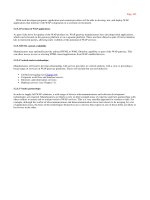
physical-layer covergence headers.) As more channels are affected by interference, the
throughput continues to drop. See Figure 10-4.
Figure 10-4. Throughput response to interference in FHSS systems
10.1.2 Gaussian Frequency Shift Keying (GFSK)
The FH PHY uses Gaussian frequency shift keying (GFSK).
[3]
Frequency shift keying
encodes data as a series of frequency changes in a carrier. One advantage of using
frequency to encode data is that noise usually changes the amplitude of a signal;
modulation systems that ignore amplitude (broadcast FM radio, for example) tend to be
relatively immune to noise. The Gaussian in GFSK refers to the shape of radio pulses;
GFSK confines emissions to a relatively narrow spectral band and is thus appropriate for
secondary uses. Signal processing techniques that prevent widespread leakage of RF
energy are a good thing, particularly for secondary users of a frequency band. By
reducing the potential for interference, GFSK makes it more likely that 802.11 wireless
LANs can be built in an area where another user has priority.
[3]
The term keying is a vestige of telegraphy. Transmission of data across
telegraph lines required the use of a key. Sending data through a modern
digital system employs modulation techniques instead, but the word keying
persists.
10.1.2.1 2-Level GFSK
The most basic GFSK implementation is called 2-level GFSK (2GFSK). Two different
frequencies are used, depending on whether the data that will be transmitted is a 1 or a 0.
To transmit a 1, the carrier frequency is increased by a certain deviation. Zero is encoded
by decreasing the frequency by the same deviation. Figure 10-5 illustrates the general
procedure. In real-world systems, the frequency deviations from the carrier are much
smaller; the figure is deliberately exaggerated to show how the encoding works.
Figure 10-5. 2-level GFSK
The rate at which data is sent through the system is called the symbol rate. Because it
takes several cycles to determine the frequency of the underlying carrier and whether 1 or
0 was transmitted, the symbol rate is a very small fraction of the carrier frequency.
Although the carrier frequency is roughly 2.4 GHz, the symbol rate is only 1 or 2 million
symbols per second.
Frequency changes with GFSK are not sharp changes. Instantaneous frequency changes
require more expensive electronic components and higher power. Gradual frequency
changes allow lower-cost equipment with lower RF leakage. Figure 10-6 shows how
frequency varies as a result of encoding the letter M (1001101 binary) using 2GFSK.
Note that the vertical axis is the frequency of the transmission. When a 1 is transmitted,
the frequency rises to the center frequency plus an offset, and when a 0 is transmitted, the
frequency drops by the same offset. The horizontal axis, which represents time, is divided
into symbol periods. Around the middle of each period, the receiver measures the
frequency of the transmission and translates that frequency into a symbol. (In 802.11
frequency-hopping systems, the higher-level data is scrambled before transmission, so the
bit sequence transmitted to the peer station is not the same as the bit sequence over the
air. The figure illustrates how the principles of 2GFSK work and doesn't step through an
actual encoding.)
Figure 10-6. 2GFSK encoding of the letter M
10.1.2.2 4-Level GFSK
Using a scheme such as this, there are two ways to send more data: use a higher symbol
rate or encode more bits of information into each symbol. 4-level GFSK (4GFSK) uses
the same basic approach as 2GFSK but with four symbols instead of two. The four
symbols (00, 01, 10, and 11) each correspond to a discrete frequency, and therefore
4GFSK transmits twice as much data at the same symbol rate. Obviously, this increase
comes at a cost: 4GFSK requires more complex transmitters and receivers. Mapping of
the four symbols onto bits is shown in Figure 10-7.
Figure 10-7. Mapping of symbols to frequencies in 4GFSK
With its more sophisticated signal processing, 4GFSK packs multiple bits into a single
symbol. Figure 10-8 shows how the letter M might be encoded. Once again, the vertical
axis is frequency, and the horizontal axis is divided into symbol times. The frequency
changes to transmit the symbols; the frequencies for each symbol are shown by the
dashed lines. The figure also hints at the problem with extending GFSK-based methods to
higher bit rates. Distinguishing between two levels is fairly easy. Four is harder. Each
doubling of the bit rate requires that twice as many levels be present, and the RF
components distinguish between ever smaller frequency changes. These limitations
practically limit the FH PHY to 2 Mbps.
Figure 10-8. 4GFSK encoding of the letter M
10.1.3 FH PHY Convergence Procedure (PLCP)
Before any frames can be modulated onto the RF carrier, the frames from the MAC must
be prepared by the Physical Layer Convergence Procedure (PLCP). Different underlying
physical layers may have different requirements, so 802.11 allows each physical layer
some latitude in preparing MAC frames for transmission over the air.
10.1.3.1 Framing and whitening
The PLCP for the FH PHY adds a five-field header to the frame it receives from the
MAC. The PLCP is a relay between the MAC and the physical medium dependent
(PMD) radio interface. In keeping with ISO reference model terminology, frames passed
from the MAC are PLCP service data units (PSDUs). The PLCP framing is shown in
Figure 10-9.
Preamble
As in a wired Ethernet, the preamble synchronizes the transmitter and receiver
and derives common timing relationships. In the 802.11 FH PHY, the Preamble is
composed of the Sync field and the Start Frame Delimiter field.
Figure 10-9. PLCP framing in the FH PHY
Sync
The sync field is 80 bits in length and is composed of an alternating zero-one
sequence (010101 01). Stations search for the sync pattern to prepare to receive
data. In addition to synchronizing the sender and receiver, the Sync field serves
three purposes. Presence of a sync signal indicates that a frame is imminent.
Second, stations that have multiple antennas to combat multipath fading or other
environmental reception problems can select the antenna with the strongest signal.
Finally, the receiver can measure the frequency of the incoming signal relative to
its nominal values and perform any corrections needed to the received signal.
Start Frame Delimiter (SFD)
As in Ethernet, the SFD signals the end of the preamble and marks the beginning
of the frame. The FH PHY uses a 16-bit SFD: 0000 1100 1011 1101.
Header
The PLCP header follows the preamble. The header has PHY-specific parameters
used by the PLCP. Three fields comprise the header: a length field, a speed field,
and a frame check sequence.
PSDU Length Word (PLW)
The first field in the PLCP header is the PLW. The payload of the PLCP frame is
a MAC frame that may be up to 4,095 bytes long. The 12-bit length field informs
the receiver of the length of the MAC frame that follows the PLCP header.
PLCP Signaling (PSF)
Bit 0, the first bit transmitted, is reserved and set to 0. Bits 1-3 encode the speed at
which the payload MAC frame is transmitted. Several speeds are available, so this
field allows the receiver to adjust to the appropriate demodulation scheme.
Although the standard allows for data rates in increments of 500 kbps from 1.0
Mbps to 4.5 Mbps, the modulation scheme has been defined only for 1.0 Mbps
and 2.0 Mbps.
[4]
See Table 10-3.
[4]
It is unlikely that significant further work will be done on high-rate,
frequency-hopping systems. For high data rates, direct sequence is a
more cost-effective choice.
Table 10-3. PSF meaning
Bits (1-2-3) Data rate
000 1.0 Mbps
001 1.5 Mbps
010 2.0 Mbps
011 2.5 Mbps
100 3.0 Mbps
101 3.5 Mbps
110 4.0 Mbps
111 4.5 Mbps
Header Error Check (HEC)
To protect against errors in the PLCP header, a 16-bit CRC is calculated over the
contents of the header and placed in this field. The header does not protect against
errors in other parts of the frame.
No restrictions are placed on the content of the Data field. Arbitrary data may contain
long strings of consecutive 0s or 1s, which makes the data much less random. To make
the transmitted data more like random white noise, the FH PHYs apply a whitening
algorithm to the MAC frame. This algorithm scrambles the data before radio
transmission. Receivers invert the process to recover the data.
10.1.4 Frequency-Hopping PMD Sublayer
Although the PLCP header has a field for the speed at which the MAC frame is
transmitted, only two of these rates have corresponding standardized PMD layers.
Several features are shared between both PMDs: antenna diversity support, allowances
for the ramp up and ramp down of the power amplifiers in the antennas, and the use of a
Gaussian pulse shaper to keep as much RF power as possible in the narrow frequency-
hopping band. Figure 10-10 shows the general design of the transceiver used in 802.11
frequency-hopping networks.
Figure 10-10. Frequency-hopping transceiver
10.1.4.1 PMD for 1.0-Mbps FH PHY
The basic frequency-hopping PMD enables data transmission at 1.0 Mbps. Frames from
the MAC have the PLCP header appended, and the resulting sequence of bits is
transmitted out of the radio interface. In keeping with the common regulatory restriction
of a 1-MHz bandwidth, 1 million symbols are transmitted per second. 2GFSK is used as
the modulation scheme, so each symbol can be used to encode a single bit. 802.11
specifies a minimum power of 10 milliwatts (mW) and requires the use of a power
control function to cap the radiated power at 100 mW, if necessary.
10.1.4.2 PMD for 2.0-Mbps FH PHY
A second, higher-speed PMD is available for the FH PHY. As with the 1.0-Mbps PMD,
the PLCP header is appended and is transmitted at 1.0 Mbps using 2GFSK. In the PLCP
header, the PSF field indicates the speed at which the frame body is transmitted. At the
higher data rate, the frame body is transmitted using a different encoding method than the
physical-layer header. Regulatory requirements restrict all PMDs to a symbol rate of 1
MHz, so 4GFSK must be used for the frame body. Two bits per symbol yields a rate of
2.0 Mbps at 1 million symbols per second. Firmware that supports the 2.0-Mbps PMD
can fall back to the 1.0-Mbps PMD if signal quality is too poor to sustain the higher rate.
10.1.4.3 Carrier sense/clear channel assessment (CS/CCA)
To implement the CSMA/CA foundation of 802.11, the PCLP includes a function to
determine whether the wireless medium is currently in use. The MAC uses both a virtual
carrier-sense mechanism and a physical carrier-sense mechanism; the physical layer
implements the physical carrier sense. 802.11 does not specify how to determine whether
a signal is present; vendors are free to innovate within the required performance
constraints of the standard. 802.11 requires that 802.11-compliant signals with certain
power levels must be detected with a corresponding minimum probability.
10.1.5 Characteristics of the FH PHY
Table 10-4 shows the values of a number of parameters in the FH PHY. In addition to the
parameters in the table, which are standardized, the FH PHY has a number of parameters
that can be adjusted to balance delays through various parts of an 802.11 frequency-
hopping system. It includes variables for the latency through the MAC, the PLCP, and
the transceiver, as well as variables to account for variations in the transceiver
electronics. One other item of note is that the total aggregate throughput of all frequency-
hopping networks in an area can be quite high. The total aggregate throughput is a
function of the hop set size. All sequences in a hop set are orthogonal and noninterfering.
In North America and most of Europe, 26 frequency-hopping networks can be deployed
in an area at once. If each network is run at the optional 2-Mbps rate, the area can have a
total of 52-Mbps throughput provided that the ISM band is relatively free of interference.
Table 10-4. FH PHY parameters
Parameter Value Notes
Slot time 50µs
SIFS time 28µs
The SIFS is used to derive the value of the other interframe
spaces (DIFS, PIFS, and EIFS).
Contention
window size
15-
1,023
slots
Preamble
duration
96µs
Preamble symbols are transmitted at 1 MHz, so a symbol takes
1 s to transmit; 96 bits require 96 symbol times.
PLCP header
duration
32µs The PLCP header is 32 bits, so it requires 32 symbol times.
Maximum
MAC frame
4,095
bytes
802.11 recommends a maximum of 400 symbols (400 bytes at
1 Mbps, 800 bytes at 2 Mbps) to retain performance across
different types of environments.
10.2 802.11 DS PHY
Direct-sequence modulation has been the most successful modulation technique used
with 802.11. The initial 802.11 specification described a physical layer based on low-
speed, direct-sequence spread spectrum (DS or DSSS). Direct-sequence equipment
requires more power to achieve the same throughput as a frequency-hopping system. 2-
Mbps direct-sequence interfaces will drain battery power more quickly than 2-Mbps
frequency-hopping interfaces. The real advantage to direct-sequence transmission is that
the technique is readily adaptable to much higher data rates than frequency-hopping
networks.
This section describes the basic concepts and modulation techniques used by the initial
DS PHY. It also shows how the PLCP prepares frames for transmission on the radio link
and touches briefly on a few details of the physical medium itself.
10.2.1 Direct-Sequence Transmission
Direct-sequence transmission is an alternative spread-spectrum technique that can be
used to transmit a signal over a much wider frequency band. The basic approach of
direct-sequence techniques is to smear the RF energy over a wide band in a carefully
controlled way. Changes in the radio carrier are present across a wide band, and receivers
can perform correlation processes to look for changes. The basic high-level approach is
shown in Figure 10-11.
Figure 10-11. Basic DSSS technique
At the left is a traditional narrowband radio signal. It is processed by a spreader, which
applies a mathematical transform to take a narrowband input and flatten the amplitude
across a relatively wide frequency band. To a narrowband receiver, the transmitted signal
looks like low-level noise because its RF energy is spread across a very wide band. The
key to direct-sequence transmission is that any modulation of the RF carrier is also spread
across the frequency band. Receivers can monitor a wide frequency band and look for
changes that occur across the entire band. The original signal can be recovered with a
correlator, which inverts the spreading process.
At a high level, a correlator simply looks for changes to the RF signal that occur across
the entire frequency band. Correlation gives direct-sequence transmissions a great deal of
protection against interference. Noise tends to take the form of relatively narrow pulses
that, by definition, do not produce coherent effects across the entire frequency band.
Therefore, the correlation function spreads out noise across the band, and the correlated
signal shines through, as illustrated in Figure 10-12.
Figure 10-12. Spreading of noise by the correlation process
Direct-sequence modulation works by applying a chipping sequence to the data stream. A
chip is a binary digit used by the spreading process. Bits are higher-level data, while
chips are binary numbers used in the encoding process. There's no mathematical
difference between a bit and a chip, but spread-spectrum developers have adopted this
terminology to indicate that chips are only a part of the encoding and transmission
process and do not carry any data. Chipping streams, which are also called pseudorandom
noise codes (PN codes), must run at a much higher rate than the underlying data. Figure
10-13 illustrates how chipping sequences are used in the transmission of data using
direct-sequence modulation. Several chips are used to encode a single bit into a series of
chips. The high-frequency chipped signal is transmitted on an RF carrier. At the other
end, a correlator compares the received signal to the same PN sequence to determine if
the encoded bit was a or a 1.
Figure 10-13. Chipping
The process of encoding a low bit rate signal at a high chip rate has the side effect of
spreading the signal's power over a much wider bandwidth. One of the most important
quantities in a direct-sequence system is its spreading ratio, which is the number of chips
used to transmit a single bit.
[5]
Higher spreading ratios improve the ability to recover the
transmitted signal but require a higher chipping rate and a larger frequency band.
Doubling the spreading ratio requires doubling the chipping rate and doubles the required
bandwidth as well. There are two costs to increased chipping ratios. One is the direct cost
of more expensive RF components operating at the higher frequency, and the other is an
indirect cost in the amount of bandwidth required. Therefore, in designing direct-
sequence systems for the real world, the spreading ratio should be as low as possible to
meet design requirements and to avoid wasting bandwidth.
[5]
The spreading ratio is related to a figure known as the processing gain.
The two are sometimes used interchangeably, but the processing gain is
slightly lower because it takes into account the effects of using real-world
systems as opposed to perfect ideal systems with no losses.
Direct-sequence modulation trades bandwidth for throughput. Compared to traditional
narrowband transmission, direct-sequence modulation requires significantly more radio
spectrum and is much slower. However, it can often coexist with other interference
sources because the receiver's correlation function effectively ignores narrowband noise.
It is easier to achieve high throughput using direct-sequence techniques than with
frequency hopping. Regulatory authorities do not impose a limit on the amount of
spectrum that can be used; they generally set a minimum lower bound on the processing
gain. Higher rates can be achieved with a wider band, though wider bands require a
higher chip rate.
10.2.1.1 802.11 direct-sequence details
For the PN code, 802.11 adopted an 11-bit Barker word. Each bit is encoded using the
entire Barker word as a chipping sequence. Detailed discussion of Barker words and their
properties are well beyond the scope of this book. The key attribute for 802.11 networks
is that Barker words have good autocorrelation properties, which means that the
correlation function at the receiver operates as expected in a wide range of environments
and is relatively tolerant to multipath delay spreads.
Regulatory authorities require a 10-dB processing gain. Using an 11-bit spreading code
for each bit allows 802.11 to meet the regulatory requirements with some margin of
safety, but it is small enough to allow as many overlapping networks as possible. Longer
spreading codes allow higher processing gains but require wider frequency channels.
10.2.1.2 Encoding in 802.11 direct-sequence networks
802.11 uses the Barker sequence {+1, -1, +1, +1, -1, +1, +1, +1, -1, -1, -1}. As used in
802.11, +1 becomes 1, and -1 becomes 0, so the Barker sequence becomes 10110111000.
It is applied to each bit in the data stream by a modulo-2 adder.
[6]
When a 1 is encoded, all
the bits in the spreading code change; for 0, they stay the same. Figure 10-14 shows the
encoding process.
[6]
Encoding with the Barker sequence is similar to a number of other
techniques. Some cellular systems, most notably in North America, use code
division multiple access (CDMA) to allow several stations to access the radio
medium. CDMA exploits some extremely complex mathematics to ensure
that transmissions from each mobile phone look like random noise to every
other mobile phone in the cell. The underlying mathematics are far more
complicated than a simple fixed pseudo-random noise code.
Figure 10-14. Encoding with the Barker word
Receivers can look at the number of 1s in a received bit time. The Barker sequence has
six 1s and five 0s. An 11-bit sequence with six 1s must therefore correspond to a
transmitted 0, and an 11-bit sequence with six 0s must correspond to a transmitted 1. In
addition to counting the numbers of 1s and 0s, the receiver can analyze the pattern of
received bits to infer the value of the transmitted bit.
10.2.1.3 Operating channels
Channels for the DS PHY are much larger than the channels for the FH PHY. The DS
PHY has 14 channels in the 2.4-GHz band, each 5 MHz wide. Channel 1 is placed at
2.412 GHz, channel 2 at 2.417 GHz, and so on up to channel 14 at 2.484 GHz. Table 10-
5 shows which channels are allowed by each regulatory authority. Channel 10 is available
throughout North America and Europe, which is why most products use channel 10 as the
default operating channel.
Table 10-5. Channels used in different regulatory domains
Regulatory domain Allowed channels
US (FCC)/Canada (IC) 1 to 11 (2.412-2.462 GHz)
Europe, excluding France and Spain (ETSI) 1 to 13 (2.412-2.472 GHz)
France 10 to 13 (2.457-2.472 GHz)
Spain 10 to 11 (2.457-2.462 GHz)
Japan (MKK) 14 (2.484 GHz)
10.2.1.4 Channel energy spread
Within a channel, most of the energy is spread across a 22-MHz band. Because the DS
PHY uses an 11-MHz chip clock, energy spreads out from the channel center in multiples
of 11 MHz, as shown in Figure 10-15. To prevent interference to adjacent channels, the
first side lobe is filtered to 30 dB below the power at the channel center frequency, and
additional lobes are filtered to 50 dB below the power at the channel center. This
corresponds to reducing the power by a factor of 1,000 and 100,000, respectively. These
limits are noted in Figure 10-15 by the use of dBr, which means dB relative to the power
at the channel center. Figure 10-15 is not to scale: -30 dBr is only one thousandth, and -
50 dBr is one hundred thousandth.
Figure 10-15. Energy spread in a single 802.11 DS transmission channel
With the transmit filters in place, RF power is confined mostly to 22-MHz frequency
bands. European regulators cap the maximum radiated power at 100 mW; the FCC in the
U.S. allows a substantially higher radiated power of 1,000 mW, but most products fall far
below this in practice.
To prevent interference from networks operating on adjacent channels, 802.11 direct-
sequence equipment must be separated by a frequency band of at least 22 MHz between
channel center frequencies. With a channel spacing of 5 MHz, networks must be
separated by five channel numbers to prevent interference, as illustrated in Figure 10-16.
If directly adjacent channels were selected, there would be a great deal of overlap in the
center lobes.
Figure 10-16. Channel separation in 802.11 DS networks
10.2.1.5 Maximum theoretical throughput
If the signal processing techniques used by the DS PHY are used, then the maximum
throughput would be a function of the frequency space used. Roughly speaking, the ISM
band is 80-MHz wide. Using the same spreading factor of 11 would lead to a maximum
bit rate of slightly more than 7 Mbps. However, only one channel would be available, and
products would need to have an oscillator running at 77 MHz to generate the chipping
sequence. High-frequency devices are a tremendous drain on batteries, and the
hypothetical high-rate encoding that uses the entire band makes terrible use of the
available spectrum. To achieve higher throughput, more sophisticated techniques must be
used. 802.11b increases the symbol rate slightly, but it gets far more mileage from more
sophisticated encoding techniques.
10.2.1.6 Interference response
Direct-sequence-modulated signals are more resistant to interference than frequency-
hopping signals. The correlation process enables direct-sequence systems to work around
narrowband interference much more effectively. With 11 chips per bit, several chips can
be lost or damaged before a single data bit is lost. The disadvantage is that the response
of direct-sequence systems to noise is not incremental. Up to a certain level, the
correlator can remove noise, but once interference obscures a certain amount of the
frequency band, nothing can be recovered. Figure 10-17 shows how direct-sequence
systems degrade in response to noise.
Figure 10-17. Throughput response to interference in DSSS systems
Direct-sequence systems also avoid interfering with a primary user more effectively than
frequency-hopping systems. After direct-sequence processing, signals are much wider
and have lower amplitudes, so they appear to be random background noise to traditional
narrowband receivers. Two direct-sequence users in the same area can cause problems
for each other quite easily if the two direct-sequence channels are not separated by an
adequate amount. Generally speaking, interference between two direct-sequence devices
is a problem long before a primary band user notices anything.
10.2.2 Differential Phase Shift Keying (DPSK)
Differential phase shift keying (DPSK) is the basis for all 802.11 direct-sequence
systems. As the name implies, phase shift keying (PSK) encodes data in phase changes of
the transmitted signal. The absolute phase of a waveform is not relevant in PSK; only
changes in the phase encode data. Like frequency shift keying, PSK resists interference
because most interference causes changes in amplitude. Figure 10-18 shows two identical
sine waves shifted by a small amount along the time axis. The offset between the same
point on two waves is the phase difference.
Figure 10-18. Phase difference between two sine waves
10.2.2.1 Differential binary phase shift keying (DBPSK)
The simplest form of PSK uses two carrier waves, shifted by a half cycle relative to each
other. One wave, the reference wave, is used to encode a 0; the half-cycle shifted wave is
used to encode a 1. Table 10-6 summarizes the phase shifts, and Figure 10-19 illustrates
the encoding as a phase difference from a preceding sine wave.
Figure 10-19. DBPSK encoding
Table 10-6. DBPSK phase shifts
Symbol Phase shift
0 0
1 180° ( radians)
To stick with the same example, encoding the letter M (1001101 in binary) is a matter of
dividing up the time into seven symbol times then transmitting the wave with appropriate
phase shift at each symbol boundary. Figure 10-20 illustrates the encoding. Time is
divided into a series of symbol periods, each of which is several times the period of the
carrier wave. When the symbol is a 0, there is no change from the phase of the previous
symbol, and when the symbol is a 1, there is a change of half a cycle. These changes
result in "pinches" of the carrier when 1 is transmitted and a smooth transition across the
symbol time boundary for 0.
Figure 10-20. The letter M encoded in DBPSK
10.2.2.2 Differential quadrature phase shift keying (DQPSK)
Like 2GFSK, DBPSK is limited to one bit per symbol. More advanced receivers and
transmitters can encode multiple bits per symbol using a technique called differential
quadrature phase shift yeying (DQPSK). Rather than a fundamental wave and a half-
cycle shifted wave, DQPSK uses a fundamental wave and three additional waves, each
shifted by a quarter cycle, as shown in Figure 10-21. Table 10-7 summarizes the phase
shifts.
Figure 10-21. DQPSK encoding
Table 10-7. DQPSK phase shifts
Symbol Phase shift
00 0
01 90° ( /2 radians)
11 180° ( radians)
10 270° (3 /2 or - /2 radians)
Now encode M in DQPSK (Figure 10-22). In the UTF-8 character set, M is represented
by the binary string 01001101 or, as the sequence of four two-bit symbols, 01-00-11-01.
In the first symbol period, there is a phase shift of 90 degrees; for clarity, the figure
shows the phase shift from a pure sine wave. The second symbol results in no phase shift,
so the wave continues without a change. The third symbol causes a phase shift of 180
degrees, as shown by the sharp change from the highest amplitude to the lowest
amplitude. The final symbol causes a phase shift of 90 degrees.
Figure 10-22. The letter M encoded in DQPSK
The obvious advantage of DQPSK relative to DBPSK is that the four-level encoding
mechanism can have a higher throughput. The cost of using DQPSK is that it cannot be
used in some environments because of severe multipath interference. Multipath
interference occurs when the signal takes several paths from the transmitter to the
receiver. Each path has a different length; therefore, the received signal from each path
has a different delay relative to the other paths. This delay is the enemy of an encoding
scheme based on phase shifts. Wavefronts are not labeled or painted different colors, so a
wavefront could arrive later than expected because of a long path or it could simply have
been transmitted late and phase shifted. In environments where multipath interference is
severe, DQPSK will break down much quicker than DBPSK.
10.2.3 DS Physical-Layer Convergence (PLCP)
As in the FH PHY, frames must be processed by the PLCP before being transmitted into
the air.
10.2.3.1 Framing and scrambling
The PLCP for the DS PHY adds a six-field header to the frames it receives from the
MAC. In keeping with ISO reference model terminology, frames passed from the MAC
are PLCP service data units (PSDUs). The PLCP framing is shown in Figure 10-23.
Figure 10-23. DS PLCP framing
The FH PHY uses a data whitener to randomize the data before transmission, but the data
whitener applies only to the MAC frame trailing the PLCP header. The DS PHY has a
similar function called the scrambler, but the scrambler is applied to the entirety of the
direct-sequence frame, including the PLCP header and preamble.
Preamble
The Preamble synchronizes the transmitter and receiver and allows them to derive
common timing relationships. It is composed of the Sync field and the Start
Frame Delimiter field. Before transmission, the preamble is scrambled using the
direct-sequence scrambling function.
Sync
The Sync field is a 128-bit field composed entirely of 1s. Unlike the FH PHY, the
Sync field is scrambled before transmission.
Start Frame Delimiter (SFD)
The SFD allows the receiver to find the start of the frame, even if some of the
sync bits were lost in transit. This field is set to 0000 0101 1100 1111, which is
different from the SFD used by the FH PHY.
Header
The PLCP header follows the preamble. The header has PHY-specific parameters
used by the PLCP. Five fields comprise the header: a signaling field, a service
identification field, a Length field, a Signal field used to encode the speed, and a
frame check sequence.
Signal
The Signal field is used by the receiver to identify the transmission rate of the
encapsulated MAC frame. It is set to either 0000 1010 (0x0A) for 1-Mbps
operation or 0001 0100 (0x14) for 2-Mbps operation.
Service
This field is reserved for future use and must be set to all 0s.
Length
This field is set to the number of microseconds required to transmit the frame as
an unsigned 16-bit integer, transmitted least significant bit to most significant bit.
CRC
To protect the header against corruption on the radio link, the sender calculates a
16-bit CRC over the contents of the four header fields. Receivers verify the CRC
before further frame processing.
No restrictions are placed on the content of the Data field. Arbitrary data may contain
long strings of consecutive 0s or 1s, which makes the data much less random. To make
the data more like random background noise, the DS PHY uses a polynomial scrambling
mechanism to remove long strings of 1s or 0s from the transmitted data stream.
10.2.4 DS Physical Medium Dependent Sublayer
Unlike the FH PHY, the DS PHY uses a single PMD specification. This is a complex and
lengthy specification that incorporates provisions for two data rates (1.0 and 2.0 Mbps).
Figure 10-24 shows the general design of a transceiver for 802.11 direct-sequence
networks.
Figure 10-24. Direct-sequence transceiver
10.2.4.1 Transmission at 1.0 Mbps
At the low data rate, the direct-sequence PMD enables data transmission at 1.0 Mbps.
The PLCP header is appended to frames arriving from the MAC, and the entire unit is
scrambled. The resulting sequence of bits is transmitted from the physical interface using
DBPSK at a rate of 1 million symbols per second. The resulting throughput is 1.0 Mbps
because one bit is encoded per symbol. Like the FH PMD, the DS PMD has a minimum
power requirement and can cap the power at 100 mW if necessary to meet regulatory
requirements.
10.2.4.2 Transmission at 2.0 Mbps
Like the FH PHY, transmission at 2.0 Mbps uses two encoding schemes. The PLCP
preamble and header are transmitted at 1.0 Mbps using DBPSK. Although using a slower
method for the header transmission reduces the effective throughput, DBPSK is far more
tolerant of noise and multipath interference. After the preamble and header are finished,
the PMD switches to DQPSK modulation to provide 2.0-Mbps service. As with the FH
PHY, most products that implement the 2.0-Mbps rate can detect interference and fall
back to lower-speed 1.0-Mbps service.
10.2.4.3 CS/CCA for the DS PHY
802.11 allows the CS/CCA function to operate in one of three modes:
Mode 1
When the energy exceeds the energy detection (ED) threshold, it reports that the
medium is busy. The ED threshold depends on the transmit power.
Mode 2
Implementations using Mode 2 must look for an actual DSSS signal and report
the channel busy when one is detected, even if the signal is below the ED
threshold.
Mode 3
Mode 3 combines Mode 1 and Mode 2. A signal must be detected with sufficient
energy before the channel is reported busy to higher layers.
Once a channel is reported busy, it stays busy for the duration of the intended
transmission, even if the signal is lost. The transmission's duration is taken from the time
interval in the Length field. Busy medium reports must be very fast. When a signal is
detected at the beginning of a contention window slot, the CCA mechanism must report a
busy medium by the time the slot has ended. This relatively high performance
requirement must be set because once a station has begun transmission at the end of its
contention delay, it should seize the medium, and all other stations should defer access
until its frame has concluded.
10.2.5 Characteristics of the DS PHY
Table 10-8 shows the values of a number of parameters in the DS PHY. In addition to the
parameters in the table, which are standardized, the DS PHY has a number of parameters
that can be adjusted to balance delays through various parts of an 802.11 direct-sequence
system. It includes variables for the latency through the MAC, the PLCP, and the
transceiver, as well as variables to account for variations in the transceiver electronics.
One other item of note is that the total aggregate throughput of all direct-sequence
networks in an area is much lower than the total aggregate throughput of all
nonoverlapping frequency-hopping networks in an area. The total aggregate throughput is
a function of the number of nonoverlapping channels. In North America and most of
Europe, three direct-sequence networks can be deployed in an area at once. If each
network is run at the optional 2-Mbps rate, the area can have a total of 6-Mbps
throughput, which is dramatically less than the frequency-hopping total aggregate
throughput.
Table 10-8. DS PHY parameters
Parameter Value Notes
Slot time 20µs
SIFS time 10µs
The SIFS is used to derive the value of the other interframe
spaces (DIFS, PIFS, and EIFS).
Contention
window size
31 to
1,023 slots
Preamble
duration
144µs
Preamble symbols are transmitted at 1 MHz, so a symbol
takes 1 s to transmit; 144 bits require 144 symbol times.
PLCP header
duration
48µs The PLCP header is 48 bits, so it requires 48 symbol times.
Maximum MAC
frame
4-8,191
bytes
Like the FH PHY, the DS PHY has a number of attributes that can be adjusted by a
vendor to balance delays in various parts of the system. It includes variables for the
latency through the MAC, the PLCP, and the transceiver, as well as variables to account
for variations in the transceiver electronics.
10.3 802.11b: HR/DSSS PHY
When the initial version of 802.11 was ratified in 1997, the real work was only just
beginning. The initial version of the standard defined FH and DS PHYs, but they were
only capable of data rates up to 2 Mbps. 2 Mbps is barely useful, especially when the
transmission capacity must be shared among all the users in an area. In 1999, the 802.11
working group released its second extension to the basic 802.11 specification. In keeping
with the IEEE numbering convention, the second extension was labeled 802.11b.
802.11b adds another physical layer into the mix. It uses the same MAC as all the other
physical layers and is based on direct-sequence modulation. However, it enables
transmission at up to 11 Mbps, which is adequate for modern networks. Higher data rates
led to a stunning commercial success. 802.11b has blazed new trails where other wireless
technologies failed to make an impact. The 802.11b PHY is also known as the high-rate,
direct-sequence PHY, abbreviated HR/DS or HR/DSSS. Even though the modulation is
different, the operating channels are exactly the same as the channels used by the original
low-rate direct sequence.
10.3.1 Complementary Code Keying
802.11 direct-sequence systems use a rate of 11 million chips per second. The original
DS PHYs divided the chip stream up into a series of 11-bit Barker words and transmitted
1 million Barker words per second. Each word encoded either one bit or two bits for a
corresponding data rate of 1.0 Mbps or 2.0 Mbps, respectively. Achieving higher data
rates and commercial utility requires that each code symbol carry more information than
a bit or two.
Straight phase shift encoding cannot hope to carry more than a few bits per code word.
DQPSK requires that receivers distinguish quarter-cycle phase differences. Further
increasing the number of bits per symbol would require processing even finer phase
shifts, such as an eighth-cycle or sixteenth-cycle shift. Detecting smaller phase shifts is
more difficult in the presence of multipath interference and requires more sophisticated
(and thus expensive) electronics.
Instead of continuing with straight phase-shift keying, the IEEE 802.11 working group
turned to an alternate encoding method. Complementary code keying (CCK) divides the
chip stream into a series of 8-bit code symbols, so the underlying transmission is based
on a series of 1.375 million code symbols per second. CCK is based on sophisticated
mathematical transforms that allow the use of a few 8-bit sequences to encode 4 or even 8
bits per code word, for a data throughput of 5.5 Mbps or 11 Mbps. In addition, the
mathematics underlying CCK transforms allow receivers to distinguish between different
codes easily, even in the presence of interference and multipath fading. Figure 10-25
illustrates the use of code symbols in CCK. It is quite similar to the chipping process used
by the slower direct-sequence layers; the difference is that the code words are derived
partially from the data. A static repeating code word such as the Barker word is not used.
Figure 10-25. Code symbols in CCK
Barker spreading, as used in the lower-rate, direct-sequence layers, uses a static code to
spread the signal over the available frequency band. CCK uses the code word to carry
information, as well as simply to spread the signal. Several phase angles are used to
prepare a complex code word of eight bits.
10.3.2 High-Rate, Direct-Sequence PLCP
Like the other physical layers, the HR/DSSS PHY is split into two parts. As with the
other physical layers, the PLCP adds additional framing information.
10.3.2.1 Framing and scrambling
Unlike the other physical layers, two options exist for the PLCP framing. Both are shown
in Figure 10-26. The "long" frame format is identical to the classic DS PLCP format and
must be supported. For efficiency and improved throughput, stations may also support the
optional "short" PLCP format.
Figure 10-26. HR/DSSS PLCP framing
Naturally, the optional short format may be used only if all stations support it. To prevent
networks configured for the short format from disappearing, 802.11b requires that
stations answering Probe Requests from an active scan return a response using the same
PLCP header that was received. If a station that supports only the long PLCP header
sends a Probe Response, an access point returns a response using the long header, even if
the BSS is configured for the short header.
Preamble
Frames begin with the preamble, which is composed of the Sync field and the
SFD field. The preamble is transmitted at 1.0 Mbps using DBPSK.
Long Sync
The Long Sync field is composed of 128 1 bits. It is processed by the scrambler
before transmission, though, so the data content varies. High-rate systems use a
specified seed for the scrambling function but support backwards compatibility
with older systems that do not specify a seed.
Short Sync
The Short Sync field is composed of 56 0 bits. Like the Long Sync, it is also
processed by the scrambler.
Long SFD
To indicate the end of the Sync field, the long preamble concludes with a Start of
Frame Delimiter (SFD). In the long PLCP, the SFD is the sequence 1111 0011
1010 0000. As with all IEEE specifications, the order of transmission from the
physical interface is least-significant bit first, so the string is transmitted right to
left.
Short SFD
To avoid confusion with the Long SFD, the Short SFD is the reverse value, 0000
0101 1100 1111.
The PLCP header follows the preamble. It is composed of the Signal, Service, Length,
and CRC fields. The long header is transmitted at 1.0 Mbps using DBPSK. However, the
short header's purpose is to reduce the time required for overhead transmission so it is
transmitted at 2.0 Mbps using DQPSK.
Long Signal
The Long Signal field indicates the speed and transmission method of the
enclosed MAC frame. Four values for the 8-bit code are currently defined and are
shown in Table 10-9.
Table 10-9. Signal field values
Speed Value (msb to lsb) Hex value
1 Mbps 0000 1010 0x0A
2 Mbps 0001 0100 0x14
5.5 Mbps 0011 0111 0x37
11 Mbps 0110 1110 0x6E
Short Signal
The Short Signal field indicates the speed and transmission method of the
enclosed frame, but only three values are defined. Short preambles can be used
only with 2 Mbps, 5.5 Mbps, and 11 Mbps networks.
Service
The Service field, which is shown in Figure 10-27, was reserved for future use by
the first version of 802.11, and bits were promptly used for the high-rate
extensions in 802.11b. First of all, the Length field describes the amount of time
used for the enclosed frame in microseconds. Above 8 Mbps, the value becomes
ambiguous. Therefore, the eighth bit of the service field is used to extend the
Length field to 17 bits. The third bit indicates whether the 802.11b
implementation uses locked clocks; clock locking means that transmit frequency
and symbol clock use the same oscillator. The fourth bit indicates the type of
coding used for the packet, which is either 0 for CCK or 1 for PBCC. All reserved
bits must be set to 0. The Service field is transmitted from left to right (b0 to b7),
which is the same in both the short and long PLCP frame formats.
Figure 10-27. Service field in the HR/DSSS PLCP header
Length
The Length field is the same in both the short and long PLCP frame formats and
is the number of microseconds required to transmit the enclosed MAC frame.
Approximately two pages of the 802.11b standard are devoted to calculating the
value of the Length frame, but the details are beyond the scope of this book.
CRC
The CRC field is the same in both the short and the long PLCP frames. Senders
calculate a CRC checksum using the Signal, Service, and Length fields. Receivers
can use the CRC value to ensure that the header was received intact and was not
damaged during transmission. CRC calculations take place before data
scrambling.
The data scrambling procedure for the HR/DSSS PHY is nearly identical to the data
scrambling procedure used with the original DS PHY. The only difference is that the
scrambling function is seeded to specified values in the HR/DSSS PHY. Different seeds
are used for short and long PLCP frames.
10.3.3 HR/DSSS PMD
Unlike the FH PHY, the DS PHY uses a single PMD specification. The general
transceiver design is shown in Figure 10-28.
Figure 10-28. HR/DSSS transceiver
10.3.3.1 Transmission at 1.0 Mbps or 2.0 Mbps
To ensure backwards compatibility with the installed base of 802.11-based, direct-
sequence hardware, the HR/DSSS PHY can transmit and receive at 1.0 Mbps or 2.0
Mbps. Slower transmissions are supported in the same manner as the lower-rate, direct-
sequence layers described in Chapter 9.
10.3.3.2 Transmission at 5.5 Mbps with CCK
Higher-rate transmission is accomplished by building on the DQPSK-based phase shift
keying techniques. DQPSK transmits two bits per symbol period, encoded as one of four
different phase shifts. By using CCK, the symbol words themselves carry additional
information. 5.5-Mbps transmission encodes four data bits into a symbol. Two are carried