AD HOC NETWORKS Technologies and Protocols phần 6 docx
Bạn đang xem bản rút gọn của tài liệu. Xem và tải ngay bản đầy đủ của tài liệu tại đây (1004.11 KB, 29 trang )
K. Tang and M. Gerla. Random access MAC for efficient broadcast support
in ad hoc networks. In Proc. of IEEE WCNC 2000.
P. Mohapatra, J. Li, and C. Gui. QoS in mobile ad hoc networks. Special
Issue on Next-Generation Wireless Multimedia Communications Systems
in IEEE Wireless Communications Magazine, June 2003.
122
Multicasting in Ad Hoc Networks
[34]
[35]
TRANSPORT LAYER PROTOCOLS IN AD HOC
NETWORKS
Karthikeyan Sundaresan
Georgia Institute of Technology
Atlanta, Georgia
Seung-Jong Park
Georgia Institute of Technology
Atlanta, Georgia
Raghupathy Sivakumar
Georgia Institute of Technology
Atlanta, Georgia
The Transmission Control Protocol (TCP) is by far the most dominant transport
protocol in the Internet and is the protocol of choice for most network applications.
The focus of this chapter is to present approaches for ad-hoc networks that provide
the same end-to-end semantics as TCP. In this regard, we first investigate the
different problems experienced by TCP in ad-hoc networks, and provide insights
into how the different design components of TCP relate to the characteristics of
such networks. We then identify three major classes of approaches to improve the
transport layer performance in ad-hoc networks. We present a protocol instance
for each of the three approaches in detail and highlight the specific problems it
addresses. We also discuss the trade-offs stemming from the adoption of each of
the protocols considered.
Ad-hoc networks, TCP
Chapter 5
Abstract
Keywords:
The Open Systems Interconnection (OSI) reference model’s fourth layer is
the transport layer, which is responsible for reliable end-to-end communication
and flow control functionalities. The TCP/IP protocol suite consists of the
Transmission Control Protocol (TCP) and User Datagram Protocol (UDP) as
the transport protocols
1
. UDP is a simplistic transport layer solution that merely
provides labeling functionality for applications. Any further functionality in
terms of reliability, flow-control, etc., is pushed up into the application. Good
examples of applications that rely on UDP are multimedia applications.
In contrast, TCP is a complex transport layer protocol that provides appli-
cations with reliable, end-to-end, connection-oriented, and in-sequence data
delivery. It performs both flow control, and congestion control on behalf of
the applications, recovers from packet losses in the network, and handles re-
sequencing of data at the receiver. Of the traffic carried by the Internet, TCP
accounts for about 90% of the bytes, with UDP accounting for the most of the
remaining traffic [1]. Although the use of UDP is increasing due to the increase
in the usage of multimedia applications, TCP continues to play a dominant role
in the Internet.
In this chapter, we focus on the design of transport layer protocols for ad-hoc
networks. The unique characteristics of ad-hoc network environments clearly
will impact the requirements imposed on a transport layer protocol. Thus, it
is interesting to both investigate from a top-down standpoint how a protocol as
well established as TCP would work over such environments, and to study from
a bottom-up standpoint what kind of transport layer behavior ad-hoc networks
necessitate. Given the dominance of TCP in terms of being the protocol of
choice for network applications, we restrict the focus of the chapter to protocols
that can support the same end-to-end semantics of reliable, in-sequence, data-
delivery as TCP.
We first present detailed arguments on how each of TCP’s design elements
relate to the characteristics of ad-hoc networks, and motivate whether or not
a fundamental re-design of the transport layer protocol is even necessary. We
arrive at the conclusion that such a re-design is indeed necessary. However, we
also identify the fact that issues of backward compatibility in certain environ-
ments (e.g. mobile host communicating with a static Internet server through
an ad-hoc network) might require staying within the TCP paradigm. In such
cases, the focus should then be on approaches to improve performance given
that TCP or a TCP-based protocol is used.
Thus, we discuss three broad classes of approaches to improve transport layer
performance over ad-hoc networks:
1
The TCP/IP protocol suite consists of four layers with the transport protocols at the third layer.
124
Transport Layer Protocols in Ad Hoc Networks
5.1
Introduction
Modified TCP: This represents a class of transport layer approaches,
where minor modifications are made to the TCP protocol to adapt it to
the characteristics of an ad-hoc network, but the fundamental elements
of TCP are still retained [2, 3].
TCP aware Cross Layer Solutions: This represents a class of lower layer
approaches that hide from TCP the unique characteristics of ad-hoc net-
works, and thus necessitate minimal changes to TCP. Such approaches
can be used in tandem with the approaches in the previous class.
For each of the classes of approaches, we discuss one representative protocol,
investigate its mechanisms, and highlight its performance. We also provide
discussions on trade-offs between the different classes of approaches, wherever
applicable.
The rest of the chapter is organized as follows: Section 5.2 consists of a brief
overview of the TCP protocol, and an in-depth study of the appropriateness of
the design elements of TCP for ad-hoc networks. Section 5.3 is a high level
introduction to the three classes of approaches considered. Sections 5.4, 5.5
and 5.6 discuss in detail specific protocol instances of the different approaches.
Finally, Section 5.7 summarizes the key conclusions of the discussions in the
chapter.
TCP and Ad-hoc Networks
125
Ad-hoc Transport Protocols: Finally, this represents a class of new built-
from-scratch transport protocols that are built specifically for the charac-
teristics of an ad-hoc network, and are not necessarily TCP-like.
5.2
TCP and Ad-hoc Networks
In this section, we investigate in detail whether or not TCP’s fundamental
design elements are appropriate for ad-hoc networks. Note that the performance
of TCP over one-hop wireless cellular data networks is well studied in related
works. Interested readers are referred to [4] for a detailed exposition on the
issues involved in operating TCP over a cellular environment and the various
approaches that have been proposed in literature toward the design of a transport
protocol for the cellular environment. However, the characteristics of multi-hop
wireless ad-hoc networks are significantly different from those of the cellular
environment and hence this calls for a study of TCP’s operation over ad-hoc
networks as well.
In the rest of the section, we first outline the different components of a TCP
connection, and then investigate how the components impact TCP’s perfor-
mance in ad-hoc networks.
126
Transport Layer Protocols in Ad Hoc Networks
Figure 5.1. Number of route errors
We use the different phases in a TCP connection’s congestion window pro-
gression to explain TCP’s fundamental design elements. TCP uses window-
based transmissions. The number of unacknowledged packets transmitted on
the channel is determined by the size of the congestion window. Hence, the
progression of the congestion window can be directly related to the through-
put enjoyed by the connection. Further, the arrival of ACKs from the TCP
receiver drives the progression of the sender’s congestion window. Initially,
when a connection is initiated, the TCP sender enters the slow-start phase. In
this phase, the congestion window is increased by one for every ACK that is
received. Hence, there is an exponential increase of the congestion window,
with the window doubling every round-trip time. Once the window size ex-
ceeds an ssthresh threshold, the window increases by one for every round-trip
time (rtt). This phase is referred to as the congestion avoidance phase where
the progression of window is linear. The sender continues to perform linear
increase, probing for more available network bandwidth. The increase contin-
ues till a loss is perceived. On experiencing a loss, the sender infers congestion
(loss-based congestion detection) and reduces the congestion window. The na-
ture of reduction depends on the nature of loss. If the loss is notified by the
arrival of triple duplicate ACKs, then a multiplicative decrease of the window
is performed, wherein the window is decreased to half its current value, and the
connection enters the congestion avoidance phase. On the other hand, if the
loss is detected through a retransmission timeout, then the window is reduced to
one and the connection enters the slow-start phase again. These basic elements
in the anatomy of a TCP connection are illustrated in Figure 5.1.
In the rest of the section, we use arguments substantiated with some packet
level network simulation results to highlight the appropriateness of the above
5.2.1
TCP Background
One of the motivating factors for TCP being window based is the avoidance
of the maintenance of any fine-grained transmission timers on a per-flow basis.
Instead, TCP uses the principle of self-clocking (ACKs triggering further data
transmissions) for connection progression. For wireline environments, where
per-flow bandwidths can scale up to several megabits per second, such a design
choice is clearly essential. However, the use of a window based transmission
mechanism in ad-hoc networks may result in the critical problem of burstiness
in packet transmissions.
Thus, if several ACKs arrive back-to-back at the sender, a burst of data
packets will be transmitted by the sender even if it were in the congestion
avoidance phase (where one packet will be transmitted for every incoming
ACK). Unfortunately, ACK bunching or several ACKs arriving at the same
time is a norm in ad-hoc networks because of the short-term unfairness of the
CSMA/CA MAC protocol typically used in such networks. [5] provides a good
exposition on the short term unfairness properties of CSMA/CA. Such short-
term unfairness results in the data stream of a TCP connection assuming control
of the channel for a short period, followed by the ACK stream assuming control
of the channel for a short period. Interestingly, such a phenomenon will occur
even when the ACK stream does not traverse the exact same path as the data
stream. This is because even if the paths were completely disjoint, the vicinity
(2-hop region in the case of CSMA/CA) of the TCP sender and the vicinity of the
TCP receiver still are common contention areas for the data and ACK streams.
Figure 5.2(a) shows the TCP sequence number progression (at the sender) in
a single TCP connection scenario. It can be seen that the transmissions occur
in periods of bursts and are interspersed with periods of inactivity due to the
arrival of ACKs. The impact of such burstiness of traffic has two undesirable
effects:
Varying round-trip time estimates: TCP relies on an accurate round-trip
time (rtt) calculation to appropriately set the timer for its retransmission
5.2.2
Window-based Transmissions
mechanisms to the specific characteristics of ad-hoc networks. For all the
simulations, FTP is used as the application generating traffic. The Newreno
version of TCP is used with Dynamic Source Routing (DSR) as the routing
protocol. Carrier Sense Multiple Access with Collision Avoidance (CSMA/CA)
in the Distributed Co-ordination Function (DCF) mode is used as the medium
access control protocol. The two ray ground reflection model is used as the
propagation model with a cross-over distance of 100m. The cross-over distance
denotes the radius within which the path loss coefficient is two and beyond which
the path loss coefficient is four. Inside the cross-over distance a line of sight
model is assumed.
TCP and Ad-hoc Networks
127
128
Transport Layer Protocols in Ad Hoc Networks
Figure 5.2. Round-trip Time and Timeouts (1 Flow)
TCP performs slow start both during connection initiation, and after expe-
riencing a retransmission timeout. For both cases, the goal of slow-start is to
probe for the available bandwidth for the connection. When a connection is
in the slow-start phase, TCP responds with two data packet transmissions for
every incoming ACK. While this exacerbates the burstiness problem discussed
earlier, there are two other problems associated with the slow-start mechanism
in the context of ad-hoc networks:
TCP and Ad-hoc Networks
129
timeout (RTO). Coupled with the low bandwidths available to flows, the
burstiness results in artificially inflating the round-trip time estimates for
packets later in a burst. Essentially, the round-trip time of a packet is
impacted by the transmission delay of the previous packets in the burst
due to the typically small available rates. TCP sets its RTO value to
where is the exponential average of rtt samples
observed, and is the standard deviation of the rtt samples. Hence,
when rtt samples vary widely due to the burstiness, the RTO values are
highly inflated, potentially resulting in significantly delayed loss recovery
(and hence under-utilization). Figures 5.2(b) and (c) show the variation
in rtt and the average maximum RTO values for the single connection,
where it can be observed that RTO values increase with an increase in
mobility.
Higher induced load: Spatial re-use in an ad-hoc network is the capa-
bility of the network to support multiple spatially disjoint transmissions.
Unfortunately, due to the burstiness and the short term capture of channel
by either the data stream or the ACK stream, the load on the underlying
channel can be higher than the average offered load. We refer to the
artificially (short-term) increased load on the underlying channel as the
induced load. If the offered load is not high, the higher induced load
will not result in any major performance degradation. However, if the
offered load itself is high (around the peak scalability of the underlying
MAC layer’s utilization curve), the utilization at the MAC layer can suffer
significantly.
5.2.3
Slow Start
Under-utilization of network resources: Although slow-start uses an ex-
ponential increase of the congestion window size, the increase mechanism
is still non-aggressive by design as it can take several rtt periods before
a connection operates at its true available bandwidth. This is not a seri-
ous problem in wireline networks as connections are expected to spend
most of their lifetimes in the congestion avoidance phase. However, be-
cause of the dynamic nature of ad-hoc networks, connections are prone
130
Transport Layer Protocols in Ad Hoc Networks
Figure 5.3. Slow-start and Loss-based Congestion Detection
TCP detects congestion through the occurrence of losses. While congestion
is by far the main source of losses in wireline networks, it is well known that
this is not the case in wireless networks. In conventional cellular wireless
networks, non-negligible random wireless channel error rates also contribute
to losses. In ad-hoc networks, in addition to congestion and random wireless
errors, mobility serves as another primary contributor to losses perceived by
connections. Random wireless errors are addressed to some extent through the
use of a semi-reliable MAC layer such as CSMA/CA that uses a positive ACK
after data reception to indicate successful reception of a packet. Interestingly,
CSMA/CA does not distinguish between whether a link is down because of the
other end moving out of range, or because of high contention at the receiver.
In either case, after attempting to transmit to a receiver for a finite number of
times, the MAC layer concludes a link failure and informs the higher layers
accordingly. Most routing protocols designed for ad-hoc networks [29, 47]
rely on such MAC feedback to trigger route-failure notification to the source.
Losses in ad-hoc networks can be classified into either link failure induced,
or congestion induced (interface queue overflows), with most of the losses
being due to link failures. Figure 5.3(b) presents the percentage of the number
of losses due to route (link) failures for different rates of mobility and loads.
It can be observed that in all the scenarios, more than 80% of the losses in
the network are due to link failures. Note that a link failure can be inferred
by the MAC layer even when it is not able to reach a neighbor due to severe
congestion. However, irrespective of the true cause of link failure inference,
the source will be notified of a route failure and a new route computation will
be performed. Figure 5.3(c) shows the percentage of time when the old route
is again chosen by the route computation mechanism. It can be observed that
TCP and Ad-hoc Networks
131
to frequent losses which in turn result in frequent timeouts and hence
more slow-start phases. Figure 5.3(a) presents the average time spent in
slow-start by the connections during the 100 second simulation. It can
be observed that connections spend a considerable amount of time in the
slow-start phase, with the proportion of time going above 50% for the
higher loads. Essentially, this means that connections spend a significant
portion of their lifetime probing for the available bandwidth in lieu of
operating at the available bandwidth.
Unfairness: TCP’s fairness properties are firmly dependent upon the
contending connections operating in congestion avoidance. When con-
nections operate primarily in the slow-start phase, the fairness properties
of TCP are more likely to be violated, since the slow start phase in TCP
is not designed keeping the fairness properties in mind.
5.2.4
Loss-based Congestion Indication
The occurrence of packet losses are identified by the TCP sender by the ar-
rival of triple duplicate ACKs and through retransmission timeouts. The ACK
stream not only helps achieve the reliability functionality of the TCP protocol,
but is also used to clock the transmission of data packets at the TCP sender. In
short, TCP relies on the periodic arrival of ACKs both to ensure reliability and
to perform effective congestion control. Most implementations of the TCP re-
ceiver send one ACK for every two packets received. This dependence on ACKs
results in two problems for ad-hoc networks: (i) Due to the overhead (about
100 bytes) associated with the request-to-send (RTS), clear-to-send (CTS), and
ACK packets used by the CSMA/CA protocol, TCP ACKs sent from the re-
ceiver to the sender can amount to 10-20% of the data stream rate. If the forward
and reverse paths happen to be the same,
2
the ACK traffic in the reverse path
2
Routin
g
protocols in ad-hoc networks may or may not choose the same path in two directions.
132
Transport Layer Protocols in Ad Hoc Networks
about 90% of the time, a different route is chosen. Essentially, most losses in
ad-hoc networks occur as a result of route failures (in reality, the MAC and
routing layer perceive most of the losses as due to route failures), and hence
treating losses as an indication of congestion turns out to be inappropriate.
5.2.5
Linear Increase Multiplicative Decrease
Once the available bandwidth has been probed by the slow start mecha-
nism, TCP enters the congestion avoidance phase where it decreases the rate of
increase in the amount of data pumped into the network, so as not to cause con-
gestion. Hence, in this phase the congestion window is increased only linearly.
Congestion avoidance is also performed immediately after a multiplicative win-
dow decrease induced by the reception of a triple dulplicate ACK. The linear
increase phase of TCP has the same drawback of slow-start – slow convergence
to the optimal operating bandwidth, and hence vulnerability to route failures
before the optimal bandwidth is attained.
The multiplicative decrease on the other hand is inappropriate for the reasons
discussed in Section 5.2.4. Essentially, most loss events in an ad-hoc network
are due to route failures, or are perceived to be due to route failures by the
underlying layers. Hence, more often than not, a loss event experienced by a
connection is followed up by a route change (see Figure 5.3(c)). While TCP’s
multiplicative decrease is an appropriate reaction to congestion, it is definitely
not an appropriate action to take when a route change has occurred, especially
given that most of the time a different route is chosen. Ideally, when a route
change occurs, TCP should enter its bandwidth estimation phase as its old
congestion window state is not relevant to the new route.
5.2.6
Dependence on ACKs and Retransmission Timeouts
TCP and Ad-hoc Networks
133
Figure
5.4. Route Errors and Impact of Losses
In the discussions thus far in the section, we have touched upon the negative
impact of mobility related losses on TCP’s performance. Losses, in addition
to being inaccurate indicators of congestion for TCP, also have an absolute
impact on the throughput performance of the TCP connection. In this section,
we profile some of the directly contributing causes for such losses.
Impact of MAC Layer. The MAC layer is responsible for detecting the
failure of a link due to congestion or mobility. Since the MAC layer (IEEE
802.11 DCF) has to go through the cycle of multiple retransmissions before
concluding link failure, there is a distinct component associated with the time
taken to actually detect link failure since the occurrence of the failure. Im-
portantly, the detection time increases with increasing load in the network. A
high MAC detection time will result in a higher likelihood of the TCP source
pumping in more packets (upto a window’s worth) into the broken path, with
all the packets being lost and the source eventually experiencing a timeout.
When a link failure is detected by the MAC layer, the link failure indication
(in DSR) is sent only to the source of the packet that triggered the detection.
If another source is using the same link in the path to its destination, the node
upstream of the link failure will wait till its MAC layer receives a packet from the
other source. Then the MAC layer will go through its cycle of retransmissions
to detect the link failure and only then would that source be informed of the
134
Transport Layer Protocols in Ad Hoc Networks
will contend with the data stream on the forward path and reduce the rate en-
joyed by the data stream. (ii) If the forward and reverse paths are not the same,
the progress of the TCP connection will be dependent on both the forward path
and reverse path reliability. Thus, the chances of a connection stalling increase
when different paths are used. Note that even if the forward and reverse paths
are different, due to the shared channel in the vicinity of the sender and the
vicinity of the receiver, the data and ACK streams will still contend with each
other. Figure 5.4(a) shows the number of times the data stream and the ACK
stream experience independent path failures for the 1 flow scenario. It can
be observed that the forward and reverse paths experience the same order of
magnitude of failures.
TCP relies on retransmission timeouts as a backup loss detection mechanism.
As described in Section 5.2.2, the RTO value for a TCP connection can be
considerably inflated and vastly different from the optimal value. Figure 5.2(c)
presents the average of the maximum RTO values set by connections during
their lifetimes. It can be observed that for higher rates of mobility, the maximum
RTO values scale up to few tens of seconds. This is true even in the case of
heavy loads. This can result in significant time delays in loss recovery, and
hence result in gross under-utilization of the available bandwidth.
5.2.7
Absolute Impact of Losses
link failure. This also contributes to the delay after which a source realizes that
a path is broken, consequently increasing the probability of timeouts. Figure
5.4(b) shows the latency involved in the MAC layer detecting a link failure. It
can be observed that for higher loads, the latency could be in the order of a few
seconds.
Both of the above factors directly contribute to more number of losses oc-
curing in the network, and thus impact the throughput performance of network
connections.
Impact of Routing Layer. The characteristics of the underlying routing
protocol have a significant impact on TCP’s performance. Some of the impor-
tant ones are outlined below.
In most of the reactive routing protocols (such as DSR), there is a provision
for the routing layer at the upstream node of a broken link to send back a path
failure message to the source. Once the source is informed of the path failure, it
initiates a new route computation. Any packet originating at the source during
this route-recomputation phase does not have a route. This directly increases
the fraction of time that packets in the routing layer spend without a route to the
destination during a connection’s lifetime. Further, the time taken to recompute
the new route also increases with increasing load. This can be observed in Figure
5.4(c) where the latency involved in route computation is presented.
In addition to the absolute impact of not having a route in the route com-
putation phase, TCP is also likely to experience timeouts during each route
computation time, especially in the heavy load scenario where route compu-
tation time is around a couple of seconds. Furthermore, successive timeouts
and the resulting back-offs could potentially result in the stalling of the data
connection.
Finally, it is in the best interest of the connection to minimize the number of
route failures resulting from the routing protocol’s operation. This is because,
the number of route failures directly influence the above two factors. As the
number of route errors increases, the fraction of time a packet spends without a
route at the routing layer increases, consequently increasing the probability of
the expiry of TCP’s retransmission timer.
Transport Layer for Ad-hoc Networks: Overview
135
5.3
Transport Layer for Ad-hoc Networks: Overview
Existing approaches to improve transport layer performance over ad-hoc
networks fall under three broad categories: (i) Modifying TCP to handle the
characteristics of an ad-hoc network, (ii) Cross-layer TCP aware modifications
to the lower layers of the protocol stack to hide from TCP the vagaries of an
ad-hoc network, (iii) Built-from-scratch transport protocols that involve a fully
re-designed transport layer approach suited for ad-hoc networks. In the rest of
136
Transport Layer Protocols in Ad Hoc Networks
the section, we provide an overview of each of the above three approaches, and
in the ensuing sections we elaborate on the details of the approaches.
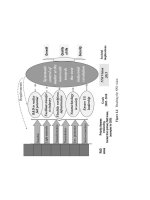
Figure 5.5. Classification of Approaches
A straight-forward and simplistic approach is to retain TCP as the trans-
port protocol, but make it mobility-aware by supplementing it with ad-
ditional mechanisms, along with simple support from the lower layers
to overcome the negative impacts of mobility. We refer to this approach
as the Modified TCP approach. While the transport layer does require
some changes in this approach, the level and complexity of changes can
be viewed as a trade-off with the performance improvements possible.
A key advantage of such an approach is that the general behavior of the
protocol is similar to that of TCP, and hence backward compatibility is-
sues, when mobile-hosts talk to static-hosts in the Internet, do not arise.
However, an obvious drawback is that the problems identified with the
design elements of TCP in Section 5.2 are still left un-addressed.
In the second approach, TCP is hidden from the underlying network char-
acteristics through appropriately designed lower layer protocols. Hence,
all the required mechanisms to mask out the negative effects of mobility
on TCP, are implemented at the MAC and routing layers. This requires
no changes to TCP’s operation. This approach is in fact more suitable
for addressing backward compatibility issues raised earlier. We refer to
this approach as TCP-aware Cross-layered Solutions. Note that unlike
in the first approach, where the underlying protocols are to a large ex-
tent TCP unaware, this approach requires the lower layers to possess a
close awareness of TCP’s properties and behavior. Also, as in the first
approach, since the mechanisms are all implemented at the routing and
The first approach involves effecting changes to the TCP protocol with sup-
port from the underlying layers in order to mask out the problems arising from
mobility. A protocol that falls in this class is the ELFN (Explicit Link Failure
Notification) protocol proposed by Holland et al. [2]. ELFN employs simple
support from the network and lower layers to achieve the purpose. The bulk
of the mechanisms in ELFN reside in the transport layer, and can be viewed as
being additional to those already present in TCP. The objective of ELFN is to
provide the TCP sender with information about link and route failures so that it
can avoid responding to the failures as if congestion occurred, and consequently
reduce any unnecessary degradation in performance. In the rest of the paper
we refer to this approach as simply TCP-ELFN.
Modified TCP
137
MAC layers without changing TCP, some of the inherent problems re-
sulting from TCP’s key design elements cannot be addressed.
Finally, the third approach is to consider a transport layer design that is
drawn from scratch, and tailored specifically for the characteristics of
an ad-hoc network. We refer to this approach as the Ad-hoc Transport
Protocol approach. An obvious drawback of such an approach is that
hosts in the ad-hoc network will now possess a transport layer protocol
that is different from TCP. While this is not a problem in stand-alone
dedicated ad-hoc networks such as those in military applications, it is an
issue when ad-hoc networks are seen to “hang-off” from the Internet. As
we show later in the chapter, such an approach can provide connections
with the best possible performance. Such an approach can also be used
as a bench-mark for the earlier two approaches.
Figure 5.5 illustrates the layers that exhibit changes in the protocol stack
for the three classes of approaches. In the following sections, we present one
instance of each of the above classes of approaches in detail. We also discuss
other related work under the three approach categories.
5.4
Modified TCP
Mechanisms
The salient features of TCP-ELFN are:
When a link failure occurs, the node upstream of the failure link sends
back an ELFN message to the source of every TCP connection using that
link. A link failure is said to occur when the MAC layer is unable to
successfully deliver a packet across the link after trying for a threshold
number of times. The notification message is sent by modifying DSR’s
route failure message to carry a payload similar to the “host unreachable”
ICMP message.
The key advantage of ELFN is that it hides the latency of route re-computations
upon path failures from the TCP layer, and prevents TCP from reacting adversely
to route-failures. Specifically, the benefits are obtained from the following fac-
tors: (i) Freezing TCP’s state prevents it from cutting down its window to one
and entering the slow start phase. This in turn reduces the number of retrans-
mission timeouts experienced by the connection. As observed in Figure 5.6(a),
for the one flow case, the timeout values are not as scattered as they are in the
default TCP case for higher mobility rates in Figure 5.2(c), and (ii) Stopping
further transmissions till a new route has been computed, thereby preventing
those packets from being lost along the broken route. This directly reduces the
number of losses suffered by the connection and consequently increases the
throughput as observed in Figures 5.6(b) and (c).
TCP-ELFN provides the flexibility to retain TCP’s existing components,
while masking any mobility related problems through additional transport layer
138
Transport Layer Protocols in Ad Hoc Networks
When the routing protocol of a source node receives the link failure
message, it first sends a route re-computation request. In addition, it
sends this ELFN message to the transport layer. When the TCP source
receives the ELFN message, it freezes its state that includes entities such
as congestion window, retransmission timers, and enters a “stand-by”
mode. While on stand-by, a packet is sent at periodic intervals to probe
the network to see if a route has been established. If an ACK is received,
then it leaves the stand-by mode, restores its retransmission timers, and
continues as normal. Packet probing instead of an explicit notice is used
to signal that a route has been re-established. When the connection enters
the “stand-by” mode, an associated timer is started. If the timer expires
before a new route is computed, then the connection is made to come out
of the “stand-by” mode to experience losses, and enter slow-start with an
initial congestion window size of one.
Variations in some parameters and actions of the protocol are also possi-
ble. In particular, the following variations have been studied: (a) Varia-
tions in the length of the interval between probe packets, (b) Modifications
to the RTO and congestion window upon restoration of the route, and (c)
Different choices for which packet to send as a probe. The impact of
each of these variations is discussed in [2].
Performance
Trade-offs
Modified TCP
139
Figure 5.6. TCP-ELFN (1 Flow)
mechanisms. However, a drawback with TCP-ELFN is that the connections
could suffer from lower throughput in heavily loaded static scenarios [8]. This
is because the MAC layer is incapable of determining if a loss is due to route
failure, or simply due to high contention. Hence, in heavily loaded static scenar-
ios, ELFN messages would be generated even in the absence of route failures.
This would make the connection enter the “stand-by” mode and wait for a new
route computation to restore its state, thereby causing a degradation in through-
put. The choice of the probing interval is a critical parameter. While a large
value could increase the time for computation of a route, thereby reducing the
throughput, a small value could increase the contention in the network due to
the frequent probe packets that are generated. Furthermore, ELFN also tries
to mask out only the negative impacts arising from route failures caused due
to mobility by freezing TCP’s state during new route computations. However,
some of the basic characteristics of TCP that degrade its performance in ad-hoc
networks are still left un-addressed.
140
Transport Layer Protocols in Ad Hoc Networks
Related Work
There have been some recent works [8] [9] [10] [11] that discuss the effect of
mobility on TCP performance and suggest various transport layer mechanisms
to solve the problems caused due to mobility. [8] studies the performance of
ELFN on static and dynamic networks and corroborates the results obtained
in [2]. [9] discusses a mechanism called TCP-Feedback, which uses route fail-
ure and re-establishment notifications to provide feedback to TCP, and thus
reduce the number of packet re-transmissions and TCP back- offs during route
calculation, to improve throughput. However, this mechanism is evaluated in
a simple one-hop wireless network. [10] studies the performance of TCP on
three different routing protocols and proposes a heuristic called fixed RTO,
which essentially freezes the TCP RTO value whenever there is a route loss.
It also evaluates the effectiveness of TCP’s selective and delayed acknowledg-
ments in improving the performance. [11] provides a transport layer solution to
improving TCP performance. It introduces a thin layer between the transport
and underlying routing layers, which puts TCP into persist mode whenever the
network gets disconnected or there are packet losses due to high bit error rate.
Thus, this thin layer acts as a shield to TCP, protecting it from the underlying
behavior of an ad-hoc network.
5.5
TCP-aware Cross-layered Solutions
An approach that falls under this category is the Atra framework proposed
by Anantharaman et. al. [12]. The framework comprises of mechanisms at
both the routing and medium access control layers and does not necessitate
any changes to TCP. The mechanisms in the Atra framework are based on the
following three goals: (i) To minimize the probability of route failures; (ii) To
predict route failures in advance and thus enable the source to recompute an
alternate route before the existing route fails; and (iii) To minimize the latency
in conveying route failure information to the source, for route failures that are
not successfully predicted. The Atra framework consists of three mechanisms
targeted toward each of the above goals respectively:
TCP-aware Cross-layered Solutions
141
Mechanisms
The key mechanisms in Atra are the following:
Symmetric Route Pinning:
The DSR routing protocol does not explicitly use symmetric routes be-
tween a source and a destination, i.e. the route taken from the source
to the destination can be different from the route taken from the desti-
nation to the source. While the use of asymmetric routes is not an issue
in a static network, in a dynamic network where nodes are mobile us-
ing an asymmetric path, increases the probability of route failure for a
connection.
Specifically, a TCP connection will stall irrespective of whether the for-
ward path is broken or the reverse path is broken. Taking the simple
scenario of using two edge-disjoint routes for the data and the ACK paths
with hop lengths of and respectively, and assuming a uniform prob-
ability of link failure for all links in the network (which is not unrealistic
given the use of the random way-point mobility model), the probability of
a path failure is Hence, in the first mechanism within
the Atra framework called symmetric route pinning (SRP), the ACK path
of a TCP connection is always kept the same as the data path in order
to reduce the probability of route failures. The mechanism implemented
at the DSR layer does the route pinning only for uni-directional commu-
nication. The reasoning is as follows: while it is true that the forward
path progression can be asynchronous to the reverse path progression,
performing route pinning to piggybacked ACKs in bi-directional com-
munication can severely increase the congestion along the path whereas
in the case of asymmetric paths, implicit load balancing is performed.
Route Failure Prediction:
The symmetric route pinning mechanism merely reduces the probability
of route failures for a connection. Hence, the second mechanism in Atra
attempts to predict the occurrence of a link failure by monitoring the
signal strength of the packets received from the corresponding neighbor.
Based on the progression of signal strengths of packet receptions from
a particular neighbor, a node predicts the occurrence of the link failure.
Maintaining a history of the progression enables nodes to dynamically
profile the speed at which the the two nodes are moving away from each
other by merely observing the slope of the progression. The threshold
to trigger a prediction is a tunable parameter that would determine the
look-ahead time for the link failure. The objective is to enable the com-
pletion of an alternate route computation before the failure of the current
path. A critical aspect of the prediction process is the propagation model
used. Since the two-ray ground reflection model is assumed for distances
greater than 100m, the corresponding equation is used to calculate the
threshold receive power corresponding to a particular slope (and hence
speed) and look-ahead time. Based on the model, the received power
can be specified as:
where K is a constant and is a function of the receive and transmitter
antenna gains and heights, and the transmit power. is the distance
between the transmitter and the receiver. Thus given a look-ahead time
and the observed relative speed between the two nodes the threshold
power to trigger a prediction can be calculated as:
where is the transmission range. The speed is computed from the
slope of the history of transmission powers observed. If the size of the
history is N (N packet reception powers and corresponding times), the
speed is calculated as follows:
where and represent the received power and time of reception for the
packet in the history. When a source receives a predicted route failure
message it issues a new route request, but continues to use the current
path either till the new route is computed or the current route fails and
it receives a normal route error. Route requests are suppressed based on
the same thresholds used to predict route failures. Hence, a route that is
close to failure will not be chosen during any route computation process.
In essence, the mechanism tries to predict link failures in advance and
proactively determine an alternate route before the failure of the route
142
Transport Layer Protocols in Ad Hoc Networks
currently being used. This would prevent the retransmission timers at
the TCP sender from firing out during route computations and leading to
a degradation in throughput or in the worst case resulting in connection
stalls due to repeated timeouts. The prediction mechanism is merely a
heuristic and can fail either by predicting link failure wrongly or failing
to predict an actual link failure. In the first scenario, the throughput of the
corresponding connection is left unaffected since the source will continue
to use the current path until a new alternate path is computed or the current
path fails. Since the current path will not fail, the source will switch its
connection only upon the recomputation of an alternate path. Further, if
the current path is the best path, it will again be recomputed as the alternate
path thus preventing any sub-optimality because of wrong predictions.
The drawback of wrong predictions is the route recomputation overhead
that is incurred. On the other hand, if a route failure is not predicted
successfully, the performance of the connection will be only as bad as
the scenario wherein no prediction mechanism is employed.
Finally, the prediction mechanism will successfully predict only mobility
related route failures. Other possibilities such as congestion based route
failures will not be captured by the prediction mechanism and will trigger
normal route errors as usual.
Proactive Route Errors (PRE):
If a link failure occurs either due to congestion, or due to mobility but
has not been successfully predicted by the prediction mechanism, the
third mechanism in Atra tries to minimize the latency involved in the
route failure information being carried to the source(s) using the link of
failure. In the default set-up, DSR will issue a route error to only the
source of the packet that triggered the link failure detection at the MAC
layer. If multiple sources are using the same link, packets will have to
arrive from them at that node before route errors will be sent back to
them increasing the latency between the link failure detection and the
time at which the sources are informed. This latency is further inflated
because subsequently arriving packets from other sources will have to
go through the MAC failure detection time cycle before the link failure
is inferred. However, in Atra each node maintains a cache of the source
identifiers of TCP connections that have used a particular link in the past
T seconds. When a link failure is detected, all sources that have used
the link in the past T seconds are informed about the link failure through
normal route errors. This reduces the latency involved in the route failure
information delivery which consequently reduces the number of losses
and also triggers earlier alternate route computations.
TCP-aware Cross-layered Solutions
143
The proactive route error mechanism can prove to be disadvantageous
when a link failure has occurred due to congestion. Consider an example
where a link between nodes A and B is traversed by 2 TCP connections
and In the default set-up, when a packet belonging to experi-
ences congestion related link failure, only would be informed of the
link failure prompting to choose a different route and thus relieving
congestion along the original path for However, when the proactive
route error mechanism is used, both and will be informed of the
route failure making both of them to recompute their routes (although the
same path might be chosen all over again). However, the characteristic
of the default set-up to let route requests through in preference to data
packets results in routes being chosen irrespective of the congestion along
the path. Hence, in the example considered there is nothing to prevent
flow from choosing the same path again even under the default set-up.
Performance
While the symmetric route pinning mechanism reduces the probability of
route failures, the route failure prediction mechanism reduces the occurrence
of route failures by predicting them proactively. These two mechanisms directly
reduce the number of retranmission timeouts in TCP. However, when a route
failure does occur, the proactive route error mechanism reduces the delay in
informing the sources of the route failure, thereby reducing the probability of a
retransmission timeout. Hence, these three mechanisms in concert reduce the
number of retransmission timeouts experienced by the connection as observed
in Figure 5.7(a) when compared to the default TCP case in Figure 5.2(c) for
the 1 connection scenario. A direct benefit of the reduction in the number
of timeouts, is the resulting reduction in the loss percentage of packets and
the consequent increase in throughput as observed in Figures 5.7 (b) and (c)
respectively.
Trade-offs
The lower layer mechanisms in the ATRA framework help improve TCP’s
performance without requiring any changes to the transport layer, by appropri-
ately taking actions to mask out the negative impacts of route failures caused due
to mobility. However, this is achieved at the cost of lower layers being required
to be TCP-aware in their operations. Also, the route prediction mechanism
relies on the signal strength of the received packets, it is challenge to make
such predictions accurate under conditions of signal fading due to obstacles,
multipath, etc. Finally, several characteristics of TCP that are by themselves
inappropriate for operation over ad-hoc networks, are not addressed by this
framework.
144
Transport Layer Protocols in Ad Hoc Networks
TCP-aware Cross-layered Solutions
145
Figure 5.7. Atra (1 Flow)
There are other research works that have attempted to identify factors affect-
ing TCP’s performance in cellular and multi-hop wireless network scenarios
[2, 3]. [2] studies the effect of routing and link layer mechanisms on TCP per-
formance. It investigates cache management strategies and discusses the effect
of link layer re-transmissions on TCP throughput. The study is conducted on
a static wireless network. [3] investigates the impact of MAC protocol on the
performance of TCP in multi-hop wireless networks.
146
Transport Layer Protocols in Ad Hoc Networks
Related Work
5.6
Ad-hoc Transport Protocol
The last approach that we discuss in this chapter involves a complete re-
design of the transport layer protocol. Though the degree of change in the
transport layer behavior through such a design is significant, the advantage is
that the designed protocol can be better tuned to the nuances and characteristics
of the target environment. A transport protocol that has adopted this approach
is the Ad-hoc Transport Protocol (ATP) proposed by Sundaresan et al.
The design of ATP is an anti-thesis of TCP’s design. Its different components
are designed in such a manner so as to solve the problems experienced by TCP
over ad-hoc networks. ATP is a rate based transport protocol with functonalities
that reside at one of three entities, namely ATP sender, intermediate nodes and
ATP receiver. The ATP sender is responsible for connection management,
reliability, congestion control, and initial rate estimation. The intermediate
nodes assist the sender in its operations by providing network feedback with
respect to congestion control and initial rate estimation. The ATP receiver is
responsible for collating the feedback information provided by the intermediate
nodes before sending the final feedback to the ATP sender for reliability, rate
and flow control.
Mechanisms
A brief outline of the functionalities of ATP are:
Congestion Control:
Every intermediate node maintains two parameters, the average queu-
ing delay experienced at the node, and the average transmission delay
at the node. Every packet generated from the source has a rate feedback
field D in its header. Whenever a packet is to be transmitted at an in-
termediate node, the value D in the packet is compared with the sum of
the parameters and calculated with respect to the current packet.
If the sum happens to be larger, the value D is replaced with this new
value. When the packet reaches the receiver, the receiver performs an ex-
ponential averaging before sending the rate feedback to the sender