all in one cisco ccie lab study guide second edition phần 9 pdf
Bạn đang xem bản rút gọn của tài liệu. Xem và tải ngay bản đầy đủ của tài liệu tại đây (667.08 KB, 89 trang )
Console> (enable) set vlan 2 5/12
VLAN 2 modified.
VLAN 1 modified.
VLAN Mod/Ports
−−−− −−−−−−−−−−−−−−−−−−−−−−−−
2
5/11−12
Activate the VLAN with the command set vlan 2.
Console> (enable) set vlan 2
Vlan 2 configuration successful
The show vlan 2 command will now indicate that VLAN2 is active and contains two ports: 5/11 and 5/12.
Console> (enable) sh vlan 2
VLAN
Name
−−−−
−−−−−−−−
2
VLAN0002
VLAN
−−−−
2
VLAN
−−−−
Type
−−−−
enet
SAID
−−−−−−
100002
Status
−−−−−−
active
MTU Parent
−−−− −−−−−−
1500 −
AREHops
−−−−−−−
STEHops
−−−−−−−
RingNo
−−−−−−
−
BrdgNo
−−−−−−
−
Mod/Ports, Vlans
−−−−−−−−−−−−−−−−
5/11−12
Stp
−−−
−
BrdgMode
−−−−−−−−
−
Trans1
−−−−−−
0
Trans2
−−−−−−
0
Backup CRF
−−−−−−−−−−
The VLAN status can also be displayed using the show vlan command. We see that all of the other Ethernet
ports still reside in the default VLAN 1.
Console> (enable) sh vlan
VLAN
Name
−−−−
−−−−−−−−−−−−−−−−−−−−−−−
1
default
2
VLAN
−−−−
1
2
1002
1003
1004
1005
VLAN
−−−−
1003
Status
−−−−−−
active
VLAN0002
1002 fddi−default
1003 token−ring−default
1004 fddinet−default
1005 trnet−default
Type
−−−−
enet
enet
fddi
trcrf
fdnet
trbrf
SAID
−−−−
100001
100002
101002
101003
101004
101005
MTU
−−−−
1500
1500
1500
1500
1500
1500
AREHops
−−−−−−−
7
Parent
−−−−−−
−
−
−
0
−
−
STEHops
−−−−−−−
7
Mod/Ports, Vlans
−−−−−−−−−−−−−−−−
2/1−2
3/1−24
5/1−10
7/1−24
10/1−24
5/11−12
active
active
active
active
active
RingNo
−−−−−−
−
−
0x0
0x0
−
−
BrdgNo
−−−−−−
−
−
−
−
0x0
0x0
12/1−16
Stp
−−−
−
−
−
−
ieee
ibm
BrdgMode
−−−−−−−−
−
−
−
−
−
−
Trans1
−−−−−−
0
0
0
0
0
0
Trans2
−−−−−−
0
0
0
0
0
0
Backup CRF
−−−−−−−−−−
off
We can verify that VLAN 2 is active by connecting to RouterA and trying to ping RouterB at IP address
192.1.1.2. We see from the output below that the ping was successful. RouterA and RouterB are now both on
VLAN 2.
RouterA#ping 192.1.1.2
685
Type escape sequence to abort.
Sending 5, 100−byte ICMP Echos to 192.1.1.2, timeout is 2 seconds:
!!!!!
Success rate is 100 percent (5/5), round−trip min/avg/max = 4/7/8 ms
Lab #93: ISL Trunk with Routing Between VLANs
Equipment Needed
The following equipment is needed to perform this lab exercise:
• Two Cisco routers with Ethernet interfaces
• One Cisco router with a 100−Mbps Ethernet interface
• A Catalyst switch
• Three Ethernet cables
• A Cisco rolled cable for console port connection to the routers
• A straight−through cable for console port connection to the Catalyst switch
Configuration Overview
This lab will demonstrate how to route between two VLANs. As shown in Figure 20−8, RouterA will reside
in VLAN 1 and RouterB will reside in VLAN 2. Both VLAN 1 and VLAN 2 reside in different IP networks.
Since the Catalyst is a layer 2 switch, it is unable to route between the two VLANs. A layer 3 router is needed
to perform this function. The solution is to define a high−speed trunk between the Catalyst switch and a
router. This trunk is referred to as an Interswitch Link (ISL) and runs over a 100−Mbps Ethernet interface.
Figure 20−8: Routing between two VLANs
Note Cisco makes many models of LAN switches. Although this lab was done using a Catalyst 5500 switch,
there are other LAN switches in the Cisco product line that could be used. For example, the Catalyst
1924 Enterprise Edition is a low−cost switch that is capable of doing VLANs and can also have a
100−Mbps ISL trunk.
Note
The Catalyst does not use the same IOS as a Cisco router. You will notice that the command set
is very different. Many items that are taken for granted on the router, such as being able to use
the tab key to complete a command, are not available on the Catalyst switch.
Note Catalyst ports are referred to by slot and port number. For example, in this lab we are connected to the
11th and 12th port of Card 5. The Catalyst will refer to these ports as 5/11 and 5/12, respectively.
Router Configuration
The configurations for the three routers in this example are as follows.
686
RouterA
Current configuration:
!
version 11.2
no service password−encryption
no service udp−small−servers
no service tcp−small−servers
!
hostname RouterA
!
interface Ethernet0/0
ip address 192.1.1.1 255.255.255.0 ← Define the IP address for the interface
connected to the Catalyst switch
!
router rip
network 192.1.1.0
!
no ip classless
!
line con 0
line aux 0
line vty 0 4
exec−timeout 30 0
login
!
end
RouterB
Current configuration:
!
version 11.2
no service password−encryption
no service udp−small−servers
no service tcp−small−servers
!
hostname RouterB
!
!
!
interface Ethernet0/0
ip address 193.1.1.1 255.255.255.0 ← Define the IP address for the interface
connected to the Catalyst switch
!
router rip
network 193.1.1.0
!
no ip classless
!
line con 0
line aux 0
line vty 0 4
exec−timeout 30 0
login
!
end
RouterC
Current configuration:
!
version 11.2
no service password−encryption
no service udp−small−servers
687
no service tcp−small−servers
!
hostname RouterC
!
interface FastEthernet1/0 ← This 100Mbps interface connects to the Catalyst
trunk port
no ip address
no logging event subif−link−status
!
interface FastEthernet1/0.1 ← This subinterface accepts traffic from VLAN 1
encapsulation isl 1 ← Define ISL encapsulation and accept traffic from VLAN 1
ip address 192.1.1.10 255.255.255.0 ← IP address for this subinterface
no ip redirects
!
interface FastEthernet1/0.2 ← This subinterface accepts traffic from VLAN 2
encapsulation isl 2 ← Define ISL encapsulation and accept traffic from VLAN 2
ip address 193.1.1.10 255.255.255.0 ← IP address for this subinterface
no ip redirects
!
router rip ← We need to dynamically route between VLAN 1 and VLAN 2. Our routes
will be learned via RIP
network 192.1.1.0 ← Propagate RIP for the network on VLAN 1
network 193.1.1.0 ← Propagate RIP for the network on VLAN 2
!
no ip classless
!
!
line con 0
line aux 0
line vty 0 4
login
!
end
Monitoring and Testing the Configuration
Let's start by setting the Catalyst 5500 to its factory default setting with the clear config all command.
Remember from the previous chapter that after the Catalyst has been reset, all of the Ethernet ports will be
assigned to VLAN 1.
Console> (enable) clear config all
This command will clear all configuration in NVRAM.
This command will cause ifIndex to be reassigned on the next system startup.
Do you want to continue (y/n) [n]? y
.......
............................
................
............................
............................
....................
System configuration cleared.
Since we will be assigning Catalyst ports to multiple VLANs, we must set the VTP domain name of the
switch with the set vtp domain command.
Console> (enable) set vtp domain CCIE_LAB
VTP domain CCIE_LAB modified
Port 5/12 is in VLAN 1 for this lab. We do not need to enter any commands to place port 5/12 into VLAN 1
since this is the default state of the Catalyst switch. Port 5/11 will be assigned to VLAN 2 for this lab. To
assign port 5/11 to VLAN 2, we use the set vlan 2 5/11 command.
Console> (enable) set vlan 2 5/11
688
Vlan 2 configuration successful
VLAN 2 modified.
VLAN 1 modified.
VLAN Mod/Ports
−−−− −−−−−−−−−−−−−−−−−−−−−−−−−−
2
5/10−11
Enable VLAN 2 with the set vlan 2 command.
Console> (enable) set vlan 2
Vlan 2 configuration successful
Port 5/10 will be the trunk port for this lab. Port 5/10 will connect to our Cisco router. We will see shortly that
port 5/10 will transmit all VLAN traffic to the Cisco router. The Cisco router will then be able to route
between our two VLANs. We need to set port 5/10 to trunk mode with the set trunk 5/10 on command.
Console> (enable) set trunk 5/10 on
Port(s) 5/10 trunk mode set to on.
The status of port 5/10 can be viewed with the show port 5/10 command. We see that the port is active and is
now defined as a trunk port. Notice that the port is running at 100−Mbps full duplex. (The a− before the full
duplex and 100 Mb indicates that these settings were autosensed by the Catalyst switch.)
Console> (enable) sh port 5/10
Port Name
Status
Vlan
−−−− −−−−
−−−−−−−−−
−−−−−
5/10
connected
trunk
Secure−Src−Addr
−−−−−−−−−−−−−−−
Level
−−−−−−
normal
Duplex
−−−−−−
a−full
Last−Src−Addr
−−−−−−−−−−−−−
Speed
−−−−−
a−100
Type
−−−−−−−−−−−−−
10/100 BaseTX
Shutdown
−−−−−−−−
No
Trap
−−−−−−−−
disabled
Port
−−−−
5/10
Security
−−−−−−−−
disabled
Port
−−−−
5/10
Port
−−−−
5/10
Broadcast−Limit
−−−−−−−−−−−−−−−
−
Status
Channel
mode
−−−−−−−−−
−−−−−−−
connected
auto
Port
−−−−
5/10
Align−Err
−−−−−−−−−
0
FCS−Err
−−−−−−−
0
Xmit−Err
−−−−−−−−
0
Rcv−Err
−−−−−−−
0
UnderSize
−−−−−−−−−
0
Port
−−−−
5/10
Single−Col
−−−−−−−−−−
0
Multi−Coll
−−−−−−−−−−
0
Late−Coll
−−−−−−−−−
0
Excess−Col
−−−−−−−−−−
0
Carri−Sen
−−−−−−−−−
0
Broadcast−Drop
−−−−−−−−−−−−−
−
Channel
Neighbor
status
device
−−−−−−−−−−− −−−−−−−−
not channel
Neighbor
port
−−−−−−−−
Runts
−−−−−
0
Giants
−−−−−−
−
Last−Time−Cleared
−−−−−−−−−−−−−−−−−−−−−−−−−
Sun May 16 1999, 02:25:04
Verify that the ports connected to RouterA and RouterB (5/12 and 5/11) are connected. Notice that port 5/11
(RouterB) is in VLAN 2, while port 5/12 (RouterA) is in VLAN 1.
Console> (enable) sh port 5/11
Port
Name
Status
Vlan
−−−−
−−−−
−−−−−−−−− −−−−
5/11
connected 2
Level
−−−−−−
normal
Duplex
−−−−−−
a−half
Speed
−−−−−
a−10
Type
−−−−−−−−−−−−
10/100BaseTX
Console> (enable) sh port 5/12
Port
Name
Status
Vlan
−−−−
−−−−
−−−−−−−−− −−−−
5/12
connected 1
Level
−−−−−−
normal
Duplex
−−−−−−
a−half
Speed
−−−−−
a−10
Type
−−−−−−−−−−−−
10/100BaseTX
689
The show trunk command gives us specific information on our trunk, showing us what VLANs are allowed
on the trunk (by default, all VLAN's are allowed on a trunk) and what VLANs are active on the trunk. We see
that in our case, all traffic from all VLANs is allowed on trunk 5/10.
Console> (enable) sh trunk
Port
Mode
Status
−−−−
−−−−
−−−−−−−−
5/10
on
trunking
Port
−−−−
5/10
Vlans allowed on trunk
−−−−−−−−−−−−−−−−−−−−−−−−−−−−−−−−−−−−−−−−−−−−−−−−−−−−−−−−−−−−−−−−−−−−−−
1−1005
Port
−−−−
5/10
Vlans allowed and active in management domain
−−−−−−−−−−−−−−−−−−−−−−−−−−−−−−−−−−−−−−−−−−−−−−−−−−−−−−−−−−−−−−−−−−−−−−
1−2,1003,1005
Port
−−−−
5/10
Vlans in spanning tree forwarding state and not pruned
−−−−−−−−−−−−−−−−−−−−−−−−−−−−−−−−−−−−−−−−−−−−−−−−−−−−−−−−−−−−−−−−−−−−−−
1−2,1003,1005
Now let's connect to RouterA and view the routing table with the show ip route command. We see that we
are learning a route to the 193.1.1.0 network. The 193.1.1.0 network connects RouterB to the Catalyst switch
on VLAN 2. The routing table on RouterA tells us that RouterC is working properly and is routing between
two VLANs.
RouterA#sh
Codes: C −
D −
N1−
E1−
i −
U −
ip route
connected, S − static, I − IGRP, R − RIP, M − mobile, B − BGP
EIGRP, EX − EIGRP external, O − OSPF, IA − OSPF inter area
OSPF NSSA external type 1, N2 − OSPF NSSA external type 2
OSPF external type 1, E2 − OSPF external type 2, E − EGP
IS−IS, L1− IS−IS level−1, L2 − IS−IS level−2, * − candidate default
per−user static route, o − ODR
Gateway of last resort is not set
C
R
192.1.1.0/24 is directly connected, Ethernet0/0
193.1.1.0/24 [120/1] via 192.1.1.10, 00:00:26, Ethernet0/0
Make sure that we have end−to−end connectivity by trying to ping RouterA at IP address 193.1.1.1. The ping
should be successful.
RouterA#ping 193.1.1.1
Type escape sequence to abort.
Sending 5, 100−byte ICMP Echos to 193.1.1.1, timeout is 2 seconds:
!!!!!
Success rate is 100 percent (5/5), round−trip min/avg/max = 4/4/4 ms
Now let's connect to RouterB. View the routing table on RouterB with the show ip router command. We see
that RouterB has learned a route to RouterA via RIP.
RouterB#sh
Codes: C −
D −
N1−
E1−
i −
U −
ip route
connected, S − static, I − IGRP, R − RIP, M − mobile, B − BGP
EIGRP, EX − EIGRP external, O − OSPF, IA − OSPF inter area
OSPF NSSA external type 1, N2 − OSPF NSSA external type 2
OSPF external type 1, E2 − OSPF external type 2, E − EGP
IS−IS, L1− IS−IS level−1, L2 − IS−IS level−2, * − candidate default
per−user static route, o − ODR
Gateway of last resort is not set
R
C
192.1.1.0/24 [120/1] via 193.1.1.10, 00:00:10, Ethernet0/0
193.1.1.0/24 is directly connected, Ethernet0/0
690
Make sure that we can ping RouterA at IP address 192.1.1.1.
RouterB#ping 192.1.1.1
Type escape sequence to abort.
Sending 5, 100−byte ICMP Echos to 192.1.1.1, timeout is 2 seconds:
!!!!!
Success rate is 100 percent (5/5), round−trip min/avg/max = 4/6/8 ms
Now connect to RouterC and view its routing table with the show ip route command. We see that RouterC
has two directly connected networks. Each of these networks is coming into RouterC on the same physical
100−Mbps Ethernet circuit. The Ethernet circuit has defined two subinterfaces, VLAN 1 is associated with
subinterface FastEthernet 1/0.1 and VLAN 2 is assigned to subinterface FastEthernet 1/0.2.
RouterC#sh
Codes: C −
D −
N1−
E1−
i −
U −
ip route
connected, S − static, I − IGRP, R − RIP, M − mobile, B − BGP
EIGRP, EX − EIGRP external, O − OSPF, IA − OSPF inter area
OSPF NSSA external type 1, N2 − OSPF NSSA external type 2
OSPF external type 1, E2 − OSPF external type 2, E − EGP
IS−IS, L1− IS−IS level−1, L2 − IS−IS level−2, * − candidate default
per−user static route, o − ODR
Gateway of last resort is not set
C
C
192.1.1.0/24 is directly connected, FastEthernet1/0.1
193.1.1.0/24 is directly connected, FastEthernet1/0.2
From RouterC, ping RouterA and RouterB to verify that the circuit is active.
RouterC#ping 192.1.1.1
Type escape sequence to abort.
Sending 5, 100−byte ICMP Echos to 192.1.1.1, timeout is 2 seconds:
!!!!!
Success rate is 100 percent (5/5), round−trip min/avg/max = 4/4/4 ms
RouterC#ping 193.1.1.1
Type escape sequence to abort.
Sending 5, 100−byte ICMP Echos to 193.1.1.1, timeout is 2 seconds:
!!!!!
Success rate is 100 percent (5/5), round−trip min/avg/max = 1/3/4 ms
Troubleshooting
{show version} The show version command displays important system−level information, including the
version of system firmware, firmware level, and serial number for each card installed in the switch, system
memory, and uptime statistics.
Console> (enable) show ver
WS−C5500 Software, Version
Copyright (c) 1995−1997 by
NMP S/W compiled on Dec 31
MCP S/W compiled on Dec 31
McpSW: 3.1(1) NmpSW: 3.1
Cisco Systems
1997, 18:36:38
1997, 18:33:15
System Bootstrap Version: 3.1(2)
Hardware Version: 1.3
Module
−−−−−−
2
3
Ports
−−−−−
2
24
Model: WS−C5500
Model
−−−−−−−−
WS−X5530
WS−X5224
Serial #: 069028115
Serial #
−−−−−−−−−
008167898
008161402
691
Hw
−−−
1.8
1.3
Fw
−−−−−−−
3.1
3.1
Fw1
−−−−−−
4.1
Sw
−−−
3.1
3.1
5
7
10
12
Module
−−−−−−
2
12
24
24
16
DRAM
Total
−−−−−−
32640K
WS−X5203
WS−X5224
WS−X5224
WS−X5030
Used
−−−−−−
11854K
008451509
008161009
008161288
007380744
FLASH
Total
−−−−−
8192K
Free
−−−−−−
20786K
1.1
1.3
1.3
1.0
3.1
3.1
3.1
1.0(117
Used
−−−−−
3224K
2.2(4)
NVRAM
Total
−−−−−
512K
Free
−−−−−
4968K
3.1
3.1
3.1
3.1
Used
−−−−
106K
Free
−−−−
406K
Uptime is 5 days, 20 hours, 14 minutes
{show module} The show module command shows what type of card is inserted into each slot of the Catalyst
switch. Burned−in MAC address information is also displayed for each card.
Console> (enable)
Mod Module−Name
−−−−−−−−−−−−−−−
2
3
5
7
10
12
Mod
−−−
2
3
5
7
10
12
Mod
−−−
2
2
show module
Ports Module−Type
−−−−− −−−−−−−−−−−−−−−−−−−−−−
2
10/100 BaseTX Supervis
24
10/100 BaseTX Ethernet
12
10/100 BaseTX Ethernet
24
10/100 BaseTX Etherne
24
10/100 BaseTX Ethernet
16
Token Ring
Model
−−−−−−−−
WS−X5530
WS−X5224
WS−X5203
WS−X5224
WS−X5224
WS−X5030
MAC−Address(es)
−−−−−−−−−−−−−−−−−−−−−−−−−−−−−−−−−−−−−−−−
00−90−f2−a7−c1−00 thru 00−90−f2−a7−c4−ff
00−10−7b−2e−ca−e8 thru 00−10−7b−2e−ca−ff
00−10−7b−09−9a−50 thru 00−10−7b−09−9a−5b
00−10−7b−3d−be−f0 thru 00−10−7b−3d−bf−07
00−10−7b−3d−be−c0 thru 00−10−7b−3d−be−d7
00:05:77:05:86:42 thru 00:05:77:05:86:52
Sub−Type
−−−−−−−−
EARL 1+
uplink
Sub−Model
−−−−−−−−−
WS−F5520
WS−U5531
Sub−Serial
−−−−−−−−−−
0008157389
0008577601
Hw
−−−
1.8
1.3
1.1
1.3
1.3
1.0
Serial−Num Status
−−−−−−−−−−−−−−−−
008167898
ok
008161402
ok
008451509
ok
008161009
ok
008161288
ok
007380744
ok
Fw
−−−
3.1(2)
3.1(1)
3.1(1)
3.1(1)
3.1(1)
1.0(117
Sw
−−−−−−
3.1(1)
3.1(1)
3.1(1)
3.1(1)
3.1(1)
3.1(1)
Sub−Hw
−−−−−−
1.1
1.1
{show mac} The show mac command displays detailed statistics on traffic passing through the Catalyst
switch. The following output has been truncated to just show the statistics for three ports on a Catalyst switch.
Notice the detailed reporting statistics for each port, including total received and transmitted frames;
multicast, unicast, and broadcast statistics; error statistics; and total octets transmitted and received.
Console> (enable) show mac
MAC
Rcv−Frms
Xmit−Frms
−−−
−−−−−−−−
−−−−−−−−−
5/10
30948
251858
5/11
44490
166061
5/12
43857
166409
Rcv−Multi
−−−−−−−−−
14649
4953
4438
Xmit−Multi
−−−−−−−−−−
251758
145105
145408
Rcv−Broad
−−−−−−−−−
08
96
15
Xmit−Broad
−−−−−−−−−−
0
5774
5823
MAC
−−−−
5/10
5/11
5/12
Dely−Exced
−−−−−−−−−−
0
0
2
In−Discard
−−−−−−−−−−
38
61
73
Lrn−Discrd
−−−−−−−−−−
0
0
0
In−Lost
−−−−−−−
0
0
0
Out−Lost
−−−−−−−−
0
0
0
Port
−−−−
5/10
5/11
5/12
Rcv−Unicast
−−−−−−−−−−−
16192
39441
39405
MTU−Exced
−−−−−−−−−
0
0
0
Rcv−Multicast
−−−−−− −−−−−−
14649
4953
4438
Rcv−Broadcast
−−−−−−−−−−−−−
108
96
15
692
Port
−−−−
5/10
5/11
5/12
Xmit−Unicast
−−−−−−−−−−−−
100
15182
15178
Xmit−Multicast
−−−−−−−−−−−−−−
251764
145107
145410
Port
−−−−
5/10
5/11
5/12
Rcv−Octet
−−−−−−−−−
3183207
20334264
20290059
Xmit−Broadcast
−−−−−−−−−−−−−−
0
5774
5823
Xmit−Octet
−−−−−−−−−−
23975586
27851660
27865755
Last−Time−Cleared
−−−−−−−−−−−−−−−−−−−−−−−−−
Sun May 16 1999, 02:25:04
{clear config all} The clear config all command causes the switch to be reset to its factory default state. In
this state, all ports reside in VLAN 1 and the Catalyst acts as a large switching hub.
Console> (enable) clear config all
This command will clear all configuration in NVRAM.
This command will cause ifIndex to be reassigned on the next system startup.
Do you want to continue (y/n) [n]? y
.......
............................
................
............................
............................
....................
System configuration cleared.
{show port} The show port command displays statistics on port−level configuration on the Catalyst switch.
The Catalyst can automatically sense speed and duplex on each port of the switch. For example, we see in the
output below that ports 5/11 and 5/12 have been automatically configured. Their status is connected, they are
both in VLAN 1, and they are both running 10−Mbps half−duplex Ethernet.
Console> (enable) sh
Port
Name
−−−−
−−−−−−−−−−−−
5/1
5/2
5/3
5/4
5/5
5/6
5/7
5/8
5/9
5/10
5/11
5/12
port
Status
−−−−−−−−−−
notconnect
notconnect
notconnect
notconnect
notconnect
notconnect
notconnect
notconnect
notconnect
notconnect
connected
connected
Vlan
−−−−
1
1
1
1
1
1
1
1
1
1
1
1
Level
−−−−−−
normal
normal
normal
normal
normal
normal
normal
normal
normal
normal
normal
normal
Duplex
−−−−−−
auto
auto
auto
auto
auto
auto
auto
auto
auto
auto
a−half
a−half
Speed
−−−−−
auto
auto
auto
auto
auto
auto
auto
auto
auto
auto
a−10
a−10
Type
−−−−−−−−−−−−−
10/100 BaseTX
10/100 BaseTX
10/100 BaseTX
10/100 BaseTX
10/100 BaseTX
10/100 BaseTX
10/100 BaseTX
10/100 BaseTX
10/100 BaseTX
10/100 BaseTX
10/100 BaseTX
10/100 BaseTX
{show port slot/port} More detailed port status is available by adding the port number after the show port
command. In the example below, we see that additional data such as MAC−level security information and
Ethernet collision and error statistics are listed for the specified port.
Console> (enable)
Port
Name
−−−−− −−−−
5/11
sh port 5/11
Status
Vlan
−−−−−−−−−
−−−−
connected
1
Level
−−−−−−
normal
Port
Secure−Src−Addr
Last−Src−Addr
Security
693
Duplex
−−−−−−
a−half
Speed
−−−−−
a−10
Shutdown
Type
−−−−−−−−−−−−−
10/100 BaseTX
Trap
−−−−
5/11
−−−−−−−−
disabled
Port
−−−−
5/11
Port
Broadcast−Limit
−−−−−−−−−−−−−−−
−
Status
Channel
mode
−−−−−−−−−
−−−−−−−
connected
auto
−−−−
5/11
−−−−−−−−−−−−−−−
−−−−−−−−−−−−−
−−−−−−−−
No
Broadcast−Drop
−−−−−−−−−−−−−−
0
Channel
Neighbor
status
device
−−−−−−−−−−− −−−−−−−−
not channel
−−−−−−−−
disabled
Neighbor
port
−−−−−−−−
Port Align−Err
−−−−− −−−−−−−−−
5/11 0
FCS−Err
−−−−−−−
0
Xmit−Err
−−−−−−−−
0
Rcv−Err
−−−−−−−
0
UnderSize
−−−−−−−−−
0
Port
−−−−
5/11
Multi−Coll
−−−−−−−−−−
0
Late−Coll
−−−−−−−−−
0
Excess−Col
−−−−−−−−−−
0
Carri−Sen
−−−−−−−−−
0
Single−Col
−−−−−−−−−−
0
Runts
−−−−−
0
Giants
−−−−−−
0
Last−Time−Cleared
−−−−−−−−−−−−−−−−−−−−−−−−−
Sun May 16 1999, 02:25:04
{show cam dynamic} The show cam dynamic command displays connected host MAC addresses that have
been learned by the switch.
Console> (enable) show cam dynamic
VLAN
Dest MAC/Route Des
Destination Ports or VCs
−−−−
−−−−−−−−−−−−−−−−−−
−−−−−−−−−−−−−−−−−−−−−−−−−−−−−−−−−−−−−−−−−−−−−−−
2
00−e0−1e−9c−8e−b0
5/10
1
00−e0−1e−9c−8e−b0
5/10
2
00−10−7b−06−c2−c1
5/11
1
00−e0−1e−5b−27−61
5/12
1
00−00−ff−ff−ff−fb
1/4
Total Matching CAM Entries Displayed = 5
{show system} The show system command displays system contacts, current and peak traffic utilization,
uptime, and thermal information.
Console> (enable) show
PS1−Status PS2−Status
−−−−−−−−−− −−−−−−−−−−
ok
none
PS1−Type
−−−−−−−−
WS−C5508
PS2−Type
−−−−−−−−
none
system
Fan−Status
−−−−−−−−−−
ok
Modem
−−−−−−
disable
System Name
−−−−−−−−−−−−−−−−−−−−−−−
Baud
−−−−
9600
Temp−Alarm Sys−Status
−−−−−−−−−− −−−−−−−−−
off
ok
Traffic
−−−−−−−
0%
Peak
−−−−
0%
System Location
−−−−−−−−−−−−−−−−−−−−−−−
Uptime d,h:m:s
−−−−−−−−−−−−−−
5,20:14:10
Logout
−−−−−−
20 min
Peak−Time
−−−−−−−−−−−−−−−−−−−−−−−−−
Sun May 16 1999, 02:25:04
System Contact
−−−−−−−−−−−−−−−−−−−−−−−
{set interface} The set interface command is used to set the IP address for inband access to the switch.
Console> (enable) set interface sc0 192.1.1.3
Interface sc0 IP address set.
{show interface} The show interface command is used to display the internal Catalyst IP addresses for
inband access and SLIP access.
Console> (enable) sh interface
sl0: flags=51<UP,POINTOPOINT,RUNNING>
slip 0.0.0.0 dest 128.73.35.160
sc0: flags=63<UP,BROADCAST,RUNNING>
vlan 1 inet 192.1.1.3 netmask 255.255.255.0 broadcast 192.1.1.255
694
{set ip permit ip−address} The set ip permit command creates an IP permit list that the Catalyst uses to
allow inband telnet and SNMP access to the switch. Up to 10 IP addresses can be defined.
Console> (enable) set ip permit 192.1.1.1
192.1.1.1 added to IP permit list.
{show ip permit} The show ip permit command is used to display the IP permit lists for the switch and to
see if any invalid IP addresses have tried to access the switch for telnet or SNMP access. The IP permit list
must be enabled with the set ip permit enable command. You can turn off the IP permit list with the set ip
permit disable command.
Console> (enable) show ip permit
IP permit list feature enabled.
Permit List
Mask
−−−−−−−−−−−−−−−−
−−−−−−−−−−−−−−−−
192.1.1.1
Denied IP Address
−−−−−−−−−−−−−−−−−
192.1.1.2
Last Accessed Time
−−−−−−−−−−−−−−−−−−
05/25/99,14:25:50
Type
−−−−−
Telnet
{set port security} The set port security command is used to define what MAC addresses are allowed to
send traffic into the switch on a per−port basis. The command shown below will cause the switch to only
allow inbound traffic on port 5/12 from a host with a MAC address of 00−e0−1e−5b−27−62. Port security can
be disabled with the set port security 5/12 disable command.
Console> (enable) set port security 5/12 enable 00−e0−1e−5b−27−62
Port 5/12 port security enabled with 00−e0−1e−5b−27−62 as the secure mac address
Trunking disabled for Port 5/12 due to Security Mode
{show vtp domain} The show vtp domain shows key domain information for the switch. The Catalyst
switch must have a domain name set before it can use VLAN numbers other than VLAN 1. The VTP domain
name is set with the set vtp domain command.
Console> (enable) sh vtp domain
Domain Name
Domain Index
−−−−−−−−−−−−−−−−−−−
−−−−−−−−−−−−
1
Vlan−count
−−−−−−−−−−
5
Last Updated
−−−−−−−−−−−−
0.0.0.0
Max−vlan−storage
−−−−−−−−−−−−−−−−
1023
V2 Mode
−−−−−−−
disabled
VTP Version
−−−−−−−−−−−
2
Config Revision
−−−−−−−−−−−−−−−
0
Pruning
−−−−−−−
disabled
Local Mode
−−−−−−−−−−
server
Password
−−−−−−−−
−
Notifications
−−−−−−−−−−−−−
disabled
PruneEligible on Vlans
−−−−−−−−−−−−−−−−−−−−−−
2−1000
{set vlan vlan_number slot_port} The set vlan command is used to place a specific port in a VLAN. The
example below assigns port 5/12 to VLAN 2. The VLAN is activated with the set vlan command.
Console> (enable) set vlan 2 5/12
VLAN 2 modified.
VLAN 1 modified.
VLAN Mod/Ports
−−−− −−−−−−−−−
2
5/11−12
{show vlan} The show vlan command displays information on all of the VLANs defined on the Catalyst
switch.
Console> (enable) sh vlan
VLAN
Name
Status
695
Mod/Ports, Vlans
−−−−
1
−−−−−−−−−−−−−−−−−−−−−−−−−−−−−
default
−−−−−−
active
2
1002
1003
1004
1005
VLAN0002
fddi−default
token−ring−default
fddinet−default
trnet−default
active
active
active
active
active
VLAN Type
SAID
MTU
Paren RingNo BrdgNo
−−−− −−−−− −−−−−−−−−− −−−−− −−−−−− −−−−−− −−−−−−
1
enet
100001 1500 −
−
−
2
enet
100002 1500 −
−
−
1002 fddi
101002 1500 −
0x0
−
1003 trcrf 101003 1500 0
0x0
−
1004 fdnet 101004 1500 −
−
0x0
1005 trbrf 101005 1500 −
−
0x0
VLAN
−−−−
1003
AREHops
−−−−−−−
7
STEHops
−−−−−−−
7
−−−−−−−−−−−−−−−−
2/1−2
3/1−24
5/1−10
7/1−24
10/1−24
5/11−12
12/1−16
Stp
−−−−
−
−
−
−
ieee
ibm
BrdgMode
−−−−−−−−
−
−
−
−
−
−
Trans1
−−−−−−
0
0
0
0
0
0
Trans2
−−−−−−
0
0
0
0
0
0
Backup CRF
−−−−−−−−−−
off
{show vlan vlan_number} When supplied with a specific VLAN number, the show vlan command displays
information on the specified VLAN. We see below that the VLAN name, status, and member ports are some
of the statistics that are displayed.
Console>
VLAN
−−−−
2
VLAN
−−−−
2
VLAN
−−−−
(enable) sh vlan 2
Name
−−−−−−−−−−−−−−−−−−−−−−−−−−
VLAN0002
Type
−−−−
enet
SAID
−−−−
100002
AREHops
−−−−−−−
MTU
−−−
1500
Parent
−−−−−−
−
STEHops
−−−−−−−
Status
−−−−−−
active
RingNo
−−−−−−
−
BrdgNo
−−−−−−
−
Mod/Ports, Vlans
−−−−−−−−−−−−−−−−−−−−−−−−−−−−
5/11−12
Stp
−−−
−
BrdgMode
−−−−−−−−
−
Trans1
−−−−−−
0
Trans2
−−−−−−
0
Backup CRF
−−−−−−−−−−
{set trunk} The set trunk command configures a Catalyst port as a trunk port.
Console> (enable) set trunk 5/10 on
Port(s) 5/10 trunk mode set to on.
{show trunk} The show trunk command displays specific information on Catalyst trunks, such as what
VLANs are allowed on the trunk and what VLANs are active on the trunk. We see that in the following output
that all traffic from all VLANs is allowed on trunk 5/10.
Console> (enable) sh trunk
Port
Mode
Status
−−−−
−−−−
−−−−−−−−
5/10
on
trunking
Port
−−−−
5/10
Vlans allowed on trunk
−−−−−−−−−−−−−−−−−−−−−−−−−−−−−−−−−−−−−−−−−−−−−−−−−−−−−−−−−−−−−−−−−−−−−−
1−1005
Port
−−−−
Vlans allowed and active in management domain
−−−−−−−−−−−−−−−−−−−−−−−−−−−−−−−−−−−−−−−−−−−−−−−−−−−−−−−−−−−−−−−−−−−−−−
696
5/10
1−2,1003,1005
Port
−−−−
5/10
Vlans in spanning tree forwarding state and not pruned
−−−−−−−−−−−−−−−−−−−−−−−−−−−−−−−−−−−−−−−−−−−−−−−−−−−−−−−−−−−−−−−−−−−−−−
1−2,1003,1005
Conclusion
This chapter has explored the operations and configuration of the Catalyst 5500, one of a family of a broad
range of LAN switches sold by Cisco. We have seen that the Catalyst switch combines the capabilities of a
switching hub with VLAN capabilities. The Catalyst can accept a router module in the form of a route switch
module (RSM), making it into a layer 2 switch and a layer 3 router in a single unit.
Several Catalyst capabilities were demonstrated in the labs, including MAC port security, IP permit lists,
routing between multiple VLANS, and ISL trunking.
697
Chapter 21: Loading the IOS Image on a Router
Overview
Topics Covered in This Chapter
• Cisco code load overview
• TFTP server configuration
• Cisco IOS naming conventions
• Loading IOS on a run from RAM router
• Loading IOS on a run from Flash router
• Loading IOS from a TFTP server
• Loading an IOS image from another router
• Troubleshooting TFTP transfers on a Cisco router
Introduction
This chapter will explain how to load an IOS image on to a Cisco router. We will examine the two types of
memory platforms on Cisco routers, run from RAM, and run from Flash systems. Finally, we will show how
to make a Cisco router into a TFTP server so that IOS code can be loaded directly from another router in your
network.
Code Load Overview
All Cisco routers store their operating system, referred to as their Internetwork Operating System or IOS, in
flash memory located on the router. Anytime a new version of the IOS needs to be loaded on the router, the
flash memory will need to be upgraded with the new code. Cisco's primary method of loading code on the
router is to load it via TFTP. TFTP is an anonymous (no password required) file transfer protocol that uses
UDP for its transport layer. The router that needs the new code requests it from a TFTP server. A TFTP server
is usually a PC or workstation running a TFTP daemon.
The TFTP server software used in this chapter is Exceed by Hummingbird Communications. Exceed includes
many powerful TCP/IP programs, such as a TFTP server and an FTP server. Exceed is configured by first
enabling the TFTP server service as shown in Figure 21−1.
698
Figure 21−1: Enabling the TFTP server service
The TFTP download and upload directories are then defined. As shown in Figure 21−2, TFTP read and write
operations will be done from a directory called download. Notice from Figure 21−2 that TFTP uses UDP port
69. Our PC has now been configured to act as a TFTP daemon.
Figure 21−2: TFTP uses UDP port 69
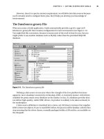
As shown in Figure 21−3, there are four IOS images in the download directory of our workstation. During the
labs in this chapter, our Cisco routers will be loading IOS images from this directory using TFTP.
Figure 21−3: IOS images in the download directory
A Cisco router also has the ability to act as a TFTP server. This feature eliminates the need for a PC or
workstation on your network that runs a TFTP server program.
Code Load Naming Conventions
Cisco IOS images adhere to a well−defined naming convention. Cisco maintains an online document on their
Web site titled, "Software Naming Conventions for IOS." The naming conventions let you interpret the
meaning of the characters in the filename of an IOS image. As an example, let's look at the IOS filenames for
two of the IOS images we will be using during this chapter.
The IOS code filename for the Cisco 3620 is: c3620−i−mz_113−8_T1.bin. This filename can be interpreted as
follows:
Hardware Platform is a Cisco 3620
↓
IP Subset Version
↓
↓
Run from RAM
Platform Specific
↓
↓
↓
↓
c3620 − i−
m z_
113−8_
T1.bin
á
á
Zipped
IOS 11.3(8)
We see that this file is an IOS image for a Cisco 3620 router. It is an IP subset code load that is compressed
and is designed to run from RAM. The IOS version is 11.3(8).
699
The IOS code filename for the Cisco 2500 is: igs−g−L_111−24.bin. This filename can be interpreted as
follows:
Hardware Platform is a Cisco 2500 Series Router
↓
ISDN Subset Version
↓
↓
Relocatable Code
↓
↓
↓
igs
−g−
L_
111−24.bin
á
IOS 11.1(24)
We see that this file is an IOS image for a Cisco 2500 router. It is an ISDN and IP code load that is
relocatable. The IOS version is 11.1(24).
Following are some more detailed descriptions of the IOS naming conventions:
• An IOS image name has three parts, each part is separated by dashes: e.g., aaaa−bbbb−cc, where:
♦ aaaa = Platform
♦ bbbbb = Feature sets
♦ cc = Where the IOS image executes from and if the IOS image is compressed
Platform
The first part of the image name specifies what platform it runs on.
as5200
c1600
c2500
c25FX
c3620
c3640
c3800
c4000
c4500
c7000
c7200
igs
5200
1600
25xx, 3xxx, 5100, AP (11.2 and later only)
Fixed Frad platform
3620
3640
3800
4000 (11.2 and later only)
4500, 4700
7000, 7010 (11.2 and later only)
7200
IGS, 25xx, 3xxx, 5100, AP
Feature Sets
The following capabilities are defined.
a − APPN
a2 − ATM
b − Appletalk
boot − used for boot images
c − Comm−server/Remote Access Server (RAS) subset (SNMP, IP, Bridging,
IPX, Atalk, Decnet, FR, HDLC, PPP, X,25, ARAP, tn3270, PT,
XRemote, LAT) (non−CiscoPro)
c − CommServer lite (CiscoPro)
c2 − Comm−server/Remote Access Server (RAS) subset (SNMP, IP, Bridging,
IPX, Atalk, Decnet, FR, HDLC, PPP, X,25, ARAP, tn3270, PT,
XRemote, LAT) (CiscoPro)
d − Desktop subset (SNMP, IP, Bridging, WAN, Remote Node, Terminal
Services, IPX, Atalk, ARAP)
(11.2 − Decnet)
d2 − reduced Desktop subset(SNMP, IP, IPX, ATALK, ARAP)
diag − IOS based diagnostics images
e − IPeXchange (no longer used in 11.3 and later)
− StarPipes DB2 Access − Enables Cisco IOS to act as a "Gateway" to
all IBM DB2 products for downstream clients/servers in 11.3T
700
eboot − ethernet boot image for mc3810 platform
f − FRAD subset (SNMP, FR, PPP, SDLLC, STUN)
f2 − modified FRAD subset, EIGRP, Pcbus, Lan Mgr removed, OSPF added
g − ISDN subset (SNMP, IP, Bridging, ISDN, PPP, IPX, Atalk)
g2 − gatekeeper proxy, voice and video
h − For Malibu(2910), 8021D, switch functions, IP Host
hdiag − Diagnostics image for Malibu(2910)
i − IP subset (SNMP, IP, Bridging, WAN, Remote Node, Terminal Services)
i2 − subset similar to IP subset for system controller image (3600)
i3 − reduced IP subset with BGP/MIB, EGP/MIB, NHRP, DIRRESP removed.
j − enterprise subset (formerly bpx, includes protocol translation)
*** not used until 10.3 ***
k − kitchen sink (enterprise for high−end) (Not used after 10.3)
k2 − high−end enterprise w/CIP2 ucode (Not used after 10.3)
k1 − Baseline Privacy key encryption (On 11.3 and up)
k2 − Triple DES (On 11.3 and up)
k3 − Reserved for future encryption capabilities (On 11.3 and up)
k4 − Reserved for future encryption capabilities (On 11.3 and up)
k5 − Reserved for future encryption capabilities (On 11.3 and up)
k6 − Reserved for future encryption capabilities (On 11.3 and up)
k7 − Reserved for future encryption capabilities (On 11.3 and up)
k8 − Reserved for future encryption capabilities (On 11.3 and up)
k9 − Reserved for future encryption capabilities (On 11.3 and up)
l − IPeXchange IPX, static routing, gateway
m − RMON (11.1 only)
n − IPX
o − Firewall (formerly IPeXchange Net Management)
p − Service Provider (IP RIP/IGRP/EIGRP/OSPF/BGP, CLNS ISIS/IGRP)
p2 − Service Provider w/CIP2 ucode
p3 − as5200 service provider
p4 − 5800 (Nitro) service provider
q − Async
q2 − IPeXchange Async
r − IBM base option (SRB, SDLLC, STUN, DLSW, QLLC) − used with
i, in, d (See note below.)
r2 − IBM variant for 1600 images
r3 − IBM variant for Ardent images (3810)
r4 − reduced IBM subset with BSC/MIB, BSTUN/MIB, ASPP/MIB, RSRB/MIB removed.
s − source route switch (SNMP, IP, Bridging, SRB) (10.2 and following)
s − (11.2 only) additions to the basic subset:
c1000 − (OSPF, PIM, SMRP, NLSP, ATIP, ATAURP, FRSVC, RSVP, NAT)
c1005 − (X.25, full WAN, OSPF, PIM, NLSP, SMRP, ATIP, ATAURP,
FRSVC, RSVP, NAT)
c1600 − (OSPF, IPMULTICAST, NHRP, NTP, NAT, RSVP, FRAME_RELAY_SVC)
AT "s" images also have: (SMRP,ATIP,AURP)
IPX "s" images also have: (NLSP,NHRP)
c2500 − (NAT, RMON, IBM, MMP, VPDN/L2F)
c2600 − (NAT, IBM, MMP, VPDN/L2F, VOIP and ATM)
c3620 − (NAT, IBM, MMP, VPDN/L2F) In 11.3T added VOIP
c3640 − (NAT, IBM, MMP, VPDN/L2F) In 11.3T added VOIP
c4000 − (NAT, IBM, MMP, VPDN/L2F)
c4500 − (NAT, ISL, LANE, IBM, MMP, VPDN/L2F)
c5200 − (PT, v.120, managed modems, RMON, MMP, VPDN/L2F)
c5300 − (MMP, VPDN, NAT, Modem Management, RMON, IBM)
c5rsm − (NAT, LANE and VLANS)
c7000 − (ISL, LANE, IBM, MMP, VPDN/L2F)
c7200 − (NAT, ISL, IBM, MMP, VPDN/L2F)
rsp
− (NAT, ISL, LANE, IBM, MMP, VPDN/L2F)
t − (11.2) AIP w/ modified Ucode to connect to Teralink 1000 Data
u − IP with VLAN RIP (Network Layer 3 Switching Software,
rsrb, srt, srb, sr/tlb)
v − VIP and dual RSP (HSA) support
v2 − Voice V2D
w − Reserved for WBU (remaining characters are specific to WBU)
i − IISP
l − LANE & PVC
p − PNNI
v − PVC traffic shaping
701
w2 − Reserved for CiscoAdvantage ED train (remaining characters are
specific to CiscoAdvantage)
a − IPX, static routing, gateway
b − Net Management
c − FR/X.25
y − Async
w3 − Reserved for Distributed Director
x − X.25 in 11.1 and earlier releases. FR/X.25 in 11.2 (IPeXchange)
H.323 Gatekeeper/Proxy in 11.3 releases for 2500, 3620, 3640
y − reduced IP (SNMP, IP RIP/IGRP/EIGRP, Bridging, ISDN, PPP) (C1003/4 )
− reduced IP (SNMP, IP RIP/IGRP/EIGRP, Bridging, WAN − X.25) (C1005)
(11.2 − includes X.25) (c1005)
y − IP variant (no Kerberos, Radius, NTP, OSPF, PIM, SMRP, NHRP...)
(c1600)
y2 − IP variant (SNMP, IP RIP/IGRP/EIGRP, WAN − X.25, OSPF, PIM)
(C1005)
y2 − IP Plus variant (no Kerberos, Radius, NTP,...) (c1600)
y3 − IP/X.31
y4 − reduced IP variant (Cable, Mibs, DHCP, EZHTTP)
z − managed modems
40 − 40−bit encryption
56 − 56−bit encryption
56i − 56−bit encryption with IPSEC
Where the IOS Image Runs From
f
m
r
l
−
−
−
−
flash
RAM
ROM
relocatable
The following may be added if the image has been 'zip' compressed:
z − zip compressed (note lowercase)
Run from RAM and Run from Flash Routers
A Cisco router executes its IOS from either RAM or flash memory. Executing from flash memory is slower.
Run from flash routers are units such as the Cisco 2500 series and some of the Cisco 1600 series routers. The
entire IOS is loaded into the flash memory in an uncompressed format. The Cisco IOS runs from the flash
memory. Upgrading the IOS becomes an issue. How can you load new code into flash memory that is
currently executing the IOS? Cisco addresses this problem by having a special IOS located in a ROM on the
router. A boot helper program reloads the router from the boot ROM. The flash can then be upgraded and the
new IOS image can be run from flash. Most run from flash routers are able to have dual banks of flash, which
will permit an IOS file to be downloaded into one bank of flash at the same time that an IOS image is running
out of the second bank of flash.
Run from RAM routers are units such as the Cisco 3600, 4000, 7000, and 7500 series. These routers store a
compressed IOS image in flash. When booting, the router copies the IOS from flash into RAM and executes
the IOS out of RAM. These run from RAM routers have their IOS upgraded by copying a new file to flash.
Since flash is not being used to execute the IOS image, you can simply TFTP the new IOS image to the
router's flash.
Commands Discussed in This Chapter
• copy tftp flash
• debug tftp
702
• show flash [all | chips | detailed | err | partition number [all | chips | detailed | err] | summary ]
• show version
• tftp server flash [partition−number:] filename
Definitions
copy tftp flash: This exec command copies a file from a TFTP server to the contents of flash memory on the
router.
debug tftp: This debug command provides output showing any TFTP transactions that occur on the router.
show flash: This exec command displays the contents of flash memory.
show version: This exec command displays router information such as system configuration, IOS level, and
the names and sources of configuration files.
tftp server: This global command specifies that the router should act as a TFTP server for the file specified
in the command.
IOS Requirements
The copy TFTP command has been available since IOS 10.0. Other features, such as the capability to make
the Cisco router into a TFTP server, have only been available since IOS 11.0.
Lab #94: Loading an IOS Image from a TFTP Server to a Run
from RAM Router
Equipment Needed
The following equipment is needed to perform this lab exercise
• One Cisco router with an Ethernet interface.
• A PC running a TFTP server program with an Ethernet card. The PC should also have a terminal
emulation program such as Procomm or Hyperterm.
• A Cisco rolled cable for console port connection to the router.
• An Ethernet hub with two Ethernet cables.
Configuration Overview
This lab will take a Cisco router that is running IOS 11.2(7) and upgrade it to IOS 11.3(8). This configuration
will demonstrate how to load an IOS image on a Cisco router that utilizes a run from RAM architecture.
Examples of run from RAM routers are the Cisco 3600 series, the Cisco 4000 series, and the Cisco 7000
series.
A PC running TFTP server software will be connected to the same LAN as a Cisco router. The software used
in this lab is Exceed from Hummingbird Communications. The Exceed software package contains many
TCP/IP programs, such as a TFTP server, an FTP server, and an X Window server. The new version of the
IOS image will reside on the PC and will be transferred to the Cisco router using the TFTP transfer protocol.
The PC will be acting as the TFTP server, and the Cisco router will be the TFTP client.
RouterA and the PC are connected as shown in Figure 21−4.
703
Figure 21−4: Connection between RouterA and the TFTP Server
Router Configuration
The configuration for the router in this example is as follows.
RouterA
Current configuration:
!
version 11.2
no service udp−small−servers
no service tcp−small−servers
!
hostname RouterA
!
!
!
interface Ethernet0/0
ip address 10.10.3.253 255.255.255.0 ← The Ethernet interface is on the same
network as the TFTP server
!
no ip classless
!
line con 0
line aux 0
line vty 0 4
login
!
end
RouterA will be loading a new IOS image from a TFTP server. RouterA's configuration does not need any
special commands to load the IOS image. The only item that needs to be configured on RouterA is the
Ethernet interface.
Monitoring and Testing the Configuration
Let's start by connecting to RouterA. Use the show version command to find out what version of IOS the
router is currently running. We see that the router is running a version of 11.2. The show version command
also tells us other key information about the router's software image and memory capabilities. We see that the
router has 16MB of DRAM. The DRAM is used to run the IOS on a run from RAM routers, such as the Cisco
3620 that we are using in this lab. We also see that this router has 16MB of flash memory. The flash memory
stores one or more IOS images. The show version output also tells us that the currently running IOS was
loaded from flash memory. Finally, we see that our router platform is a 3620 router.
RouterA#show version
Router is running IOS version 11.2(7a)P
Cisco Internetwork Operating System Software ↓
IOS (tm) 3600 Software (C3620−I−M), Version 11.2(7a)P, SHARED
PLATFORM, RELEASE
SOFTWARE (fc1)
Copyright (c) 1986−1997 by cisco Systems, Inc.
Compiled Wed 02−Jul−97 08:25 by ccai
Image text−base: 0x600088E0, data−base: 0x60440000
704
ROM: System Bootstrap, Version 11.1(7)AX [kuong (7)AX], EARLY DEPLOYMENT
RELEASE SOFTWARE (fc2)
RouterA uptime is 54 minutes
The IOS was loaded from flash memory
System restarted by reload
↓
System image file is "flash:c3620−i−mz.112−7a.P", booted via flash
This router is a Cisco 3620
↓
cisco 3620 (R4700) processor (revision 0x81) with 12288K/4096K
bytes of memory.
Processor board ID 05706232
á
R4700 processor, Implementation 33, Revision 1.0
The router has 16MB of DRAM.
The DRAM is broken up into
12MB of main memory, used for
processing, and 4MB of shared
memory user for I/O
Bridging software.
X.25 software, Version 2.0, NET2, BFE and GOSIP compliant.
Basic Rate ISDN software, Version 1.0.
1 Ethernet/IEEE 802.3 interface(s)
1 Serial network interface(s)
1 ISDN Basic Rate interface(s)
DRAM configuration is 32 bits wide with parity disabled.
29K bytes of non−volatile configuration memory.
16384K bytes of processor board System flash (Read/Write) ← The router has 16MB
of flash memory
Configuration register is 0x2102
Typeconnecting to RouterA. Use the the show flash command to view the contents of the flash memory on
the router. We see that the flash memory contains a single file, c3620−i−mz.112−7a.P. The size of the file is
2259976 bytes. The flash memory is 16MB in size.
RouterA#show flash
System flash directory:
File Length
Name/status
1
2259976 c3620−i−mz.112−7a.P ← There is only a single file in flash
memory
[2260040 bytes used, 14517176 available, 16777216 total]
16384K bytes of processor board System flash (Read/Write)
á
16MB of flash memory on this router
Let's make sure that we can reach our TFTP server at IP address 10.10.3.28 by using a ping command.
RouterA#ping 10.10.3.28
Type escape sequence to abort.
Sending 5, 100−byte ICMP Echos to 10.10.3.28, timeout is 2 seconds:
!!!!!
Success rate is 100 percent (5/5), round−trip min/avg/max = 1/3/8 ms
Once connecting to RouterA. Use thewe are sure we can reach the TFTP server, we can start loading the new
IOS image to the router. Use the copy tftp flash command to start a TFTP transfer from the PC to the flash
memory of RouterA. Notice that we will specify not to erase the current file that resides in the flash memory
of the router.
RouterA#copy tftp flash
System flash directory:
File Length
Name/status
1
2259976 c3620−i−mz.112−7a.P
[2260040 bytes used, 14517176 available, 16777216 total]
705
Address or name of remote host [10.10.3.28]? ← Address of TFTP server
Source file name? c3620−i−mz_113−8_T1.bin ← Name of IOS image we want to load
Destination file name [c3620−i−mz_113−8_T1.bin]?
Accessing file 'c3620−i−mz_113−8_T1.bin' on 10.10.3.28...
Loading c3620−i−mz_113−8_T1.bin from 10.10.3.28 (via Ethernet0/0): ! [OK]
Erase flash device before writing? [confirm]n ← Do not erase the current file
in the router's flash memory
Copy 'c3620−i−mz_113−8_T1.bin' from server
as 'c3620−i−mz_113−8_T1.bin' into Flash WITHOUT erase? [yes/no]y
Loading c3620−i−mz_113−8_T1.bin from 10.10.3.28 (via Ethernet0/0): !!!!!!!!!!!
!!!!!!!!!!!!!!!!!!!!!!!!!!!!!!!!!!!!!!!!!!!!!!!!!!!!!!!!!!!!!!!!!!!!!!!!!!!!!!
!!!!!!!!!!O!!!!!!!!!!!!!!!!!!!!!!!!!!!!!!!!!!!!!!!!!!!!!!!!!!!!!!!!!!
á
An O means that a TFTP packet was received out of order
!!!!!!!!!!!!!!!!!!!!!!!!!!!!!!!!!!!!!!!!!!!!!!!!!!!!!!!!O!!!!!!!!!!!!!!!!!!!!!
!!!!!!!!!!!!!!!!!!!!!!!!!!!!!!!!!!!!!!!!!!!!!!!!!!!!!!!!!!!!!!!!!!!!!!!!!!!!!!
!!!!!!!!!!!!!!O!!!!!!!!!!!!!!!!!!!!!!!!!!!!!!!!!!!!!!!!!!!!!!!!!!!!!!!!!!!!!!!
!!!!!!!!!!!!!!!!!!!!!!!!!!!!!!!!!!!!!!!!!!!!!!!!!O!!!!!!!!!!!!!!!!!!!!!!!!!!!!
!!!!!!!!!!!!!!!!!!!!!!!!!!!!!!!!!!!!!!!!!!!!!!!!!!!!!!!!!!!!!!!!!!!!!!!!!!!
!!!!!!!!!!!O!!!!!!!!!!!!!!!!!!!!!!!!!!!!!!!!!!!!!!!!!!!!!!!!!!!!!!!!!!!!!!!!!!
!!!!!!!!!!!!!!!!!!!!!!!!!!!!!!!!
[OK − 3332232/14517176 bytes]
Verifying checksum . . .
OK (0x1837)
Flash device copy took 00:00:35 [hh:mm:ss]
After the file download is complete, check the contents of the router's flash memory with the show flash
command. We see that there are now two files in the flash memory of the router.
RouterA#show flash
System flash directory:
File Length
Name/status
1
2259976 c3620−i−mz.112−7a.P
2
3332232 c3620−i−mz_113−8_T1.bin ← New file that we just loaded
[5592336 bytes used, 11184880 available, 16777216 total]
16384K bytes of processor board System flash (Read/Write)
Sinceconnecting to RouterA. Use the there are two files in the flash memory, we need to tell the router which
file to load during its power on sequence. Enter router configuration mode with the config term command.
Enter the boot system flash command shown next.
RouterA#config term
Enter configuration commands, one per line. End with CNTL/Z.
RouterA(config)#boot system flash c3620−i−mz_113−8_T1.bin
RouterA(config)#exit
You can verify that this command has been properly entered with the show run command.
RouterA#show run
Building configuration...
Current configuration:
!
version 11.2
no service udp−small−servers
no service tcp−small−servers
!
hostname RouterA
!
boot system flash c3620−i−mz_113−8_T1.bin ← The router will load this file from
flash memory during its power on
sequence
706
!
interface Ethernet0/0
ip address 10.10.3.253 255.255.255.0
!
no ip classless
!
line con 0
line aux 0
line vty 0 4
login
!
end
The connecting to RouterA. Use theconfiguration changes must be written with a write mem command, since
we have to reload the router.
RouterA#write mem
Building configuration...
[OK]
RouterA#reload
Proceed with reload? [confirm]
After the router reloads, it will be running IOS version 11.3(8)T1. We see that this file has been loaded from
router flash.
RouterA#show ver
Cisco Internetwork Operating System Software
IOS (tm) 3600 Software (C3620−I−M), Version 11.3(8)T1,
RELEASE SOFTWARE (fc1)
Copyright (c) 1986−1999 by cisco Systems, Inc.
Compiled Thu 11−Feb−99 17:22 by ccai
Image text−base: 0x60008918, data−base: 0x605B8000
ROM: System Bootstrap, Version 11.1(7)AX [kuong (7)AX], EARLY
DEPLOYMENT RELEASE SOFTWARE (fc2)
RouterA uptime is 5 minutes
System restarted by reload
System image file is "flash:c3620−i−mz_113−8_T1.bin",
booted via flash
cisco 3620 (R4700) processor (revision 0x81) with 12288K/4096K
bytes of memory.
Processor board ID 05706232
R4700 processor, Implementation 33, Revision 1.0
Bridging software.
X.25 software, Version 3.0.0.
Basic Rate ISDN software, Version 1.1.
1 Ethernet/IEEE 802.3 interface(s)
1 Serial network interface(s)
1 ISDN Basic Rate interface(s)
DRAM configuration is 32 bits wide with parity disabled.
29K bytes of non−volatile configuration memory.
16384K bytes of processor board System flash (Read/Write)
Configuration register is 0x2102
As an alternative, you can also load an IOS image to the router and erase the contents of the router's flash
memory. We see an example here where there are two files in the flash memoryconnecting to RouterA. Use
the of the router.
RouterA#show flash
System flash directory:
707
File Length
Name/status
1
2259976 c3620−i−mz.112−7a.P
2
3332232 c3620−i−mz_113−8_T1.bin
[5592336 bytes used, 11184880 available, 16777216 total]
16384K bytes of processor board System flash (Read/Write)
If you want to load a new IOS image without keeping the old image, use the copy tftp flash command and
allow the flash device to be erased before writing.
RouterA#copy tftp flash
System flash directory:
File Length
Name/status
1
2259976 c3620−i−mz.112−7a.P
2
3332232 c3620−i−mz_113−8_T1.bin
[5592336 bytes used, 11184880 available, 16777216 total]
Address or name of remote host [10.10.3.28]? 10.10.3.28
Source file name? c3620−i−mz_113−8_T1.bin
Destination file name [c3620−i−mz_113−8_T1.bin]?
Accessing file 'c3620−i−mz_113−8_T1.bin' on 10.10.3.28 . . .
Loading c3620−i−mz_113−8_T1.bin from 10.10.3.28 (via Ethernet0/0): ! [OK]
Erase flash device before writing? [confirm] ← Pressing enter at this prompt
will cause the flash to be erased before
writing a new file
Flash contains files. Are you sure you want to erase? [confirm]
Copy 'c3620−i−mz_113−8_T1.bin' from server
as 'c3620−i−mz_113−8_T1.bin' into Flash WITH erase? [yes/no]y
Erasing device ... eeeeeeeeeeeeeeeeeeeeeeeeeeeeeeeeeeeeeeeeeeeeeeeee
eeeeeeeeeeeeeee ... erased
á
The flash is being erased
Loading c3620−i−mz_113−8_T1.bin from 10.10.3.28 (via Ethernet0/0):
!!!!!!!!!!!!!!!!!!!!!!!!!!!!!O!!!!!!!!!!!!!!!!!!!!!!!!!!!!!!!!!!!!!!!!O!!!!!!!!
á
An O means that a TFTP packet was received out of order
!!!!!!!!!!!!!!!!!!!!!!!!!!!!!!!!!!!!!!!!!!!!!!!!!!!!!!!!!!!!!!!!!!!!O!!!!!!!!!!!!!!!!!!!!
!!!!!!!!!!!!!!!!!!!O!!!
!!!!!!!!!!!!!!!!!!!!!!!!!!!!!!!!!!!!!!!!!!!!!!!!!!!!!!!!!!!!!!!!!!!!!!!!!O!!!!!!!!!!!!!!!
!!!!!!!!!!!!!!!!!!!!!!!
O!!!!!!!!!!!!!!!!!!!!!!!!!!!!!!!!!!!!!!!!!!!!!!!!!!!!!!!!!!!!!!!!!!!!!!!!!!!!!O!!!!!!!!!!
!!!!!!!!!!!!!!!!!!!!!!!
!!!!!O!!!!!!!!!!!!!!!!!!!!!!!!!!!!!!!!!!!!!!!!!!!!!!!!!!!!!!!!!!!!!!!!!!!!!!!!!!!!!O!!!!!
!!!!!!!!!!!!!!!!!!!!!!!
!!!!!!!!!!!!O!!!!!!!!!!!!!!!!!!!!!!!!!!!!!!!!!!!!!!!!!!!!!!!!!!!!!!!!!!!!!!!!!!!!!!!!!!!!
!!!O!!!!!!!!!!!!!!!!!!!
!!!!!!!!!!!!!!!!!!!!!O!!
[OK − 3332232/16777216 bytes]
Verifying checksum... OK (0x1837)
Flash device copy took 00:00:34 [hh:mm:ss]
After connecting to RouterA. Use thethe IOS download is complete, we see that there is only one file in the
flash device, since we allowed the router to erase the flash before starting the download.
RouterA#sh flash
System flash directory:
File Length
Name/status
1
3332232 c3620−i−mz_113−8_T1.bin
[3332296 bytes used, 13444920 available, 16777216 total]
16384K bytes of processor board System flash (Read/Write)
708
Lab #95: Loading an IOS Image from a TFTP Server to a Run
from Flash Router
Equipment Needed
Theconnecting to RouterA. Use the following equipment is needed to perform this lab exercise:
• One Cisco router with an Ethernet interface.
• A PC running a TFTP server program with an Ethernet card. The PC should also have a terminal
emulation program such as Procomm or Hyperterm.
• A Cisco rolled cable for console port connection to the router.
• An Ethernet Hub with two Ethernet cables.
Configuration Overview
This configuration will demonstrate how to load an IOS image on a Cisco router that utilizes a run from flash
architecture. Examples of run from flash routers are the Cisco 2500 series and some of the Cisco 1600 series.
A PC running TFTP server software will be connected to the same LAN as a Cisco router. The software used
in this lab is Exceed from Hummingbird Communications. The Exceed software package contains many
TCP/IP programs such as a TFTP server, an FTP server, and an X Windows server. The new version of the
IOS image will reside on the PC and will be transferred to the Cisco router using the TFTP transfer protocol.
The PC will be acting as the TFTP server, and the Cisco router will be the TFTP client.
RouterC and the PC are connected as shown in Figure 21−5.
Figure 21−5: Connection between RouterC and the TFTP Server
Router Configuration
The configuration for the router in this example is as follows.
RouterC
Current configuration:
!
version 11.1
service udp−small−servers
service tcp−small−servers
!
hostname RouterC
!
!
interface Ethernet0
ip address 10.10.3.253 255.255.255.0 ← The Ethernet interface is on the same
network as the TFTP server
!
no ip classless
!
line con 0
709