CCIE Professional Development Large-Scale IP Network Solut phần 3 docx
Bạn đang xem bản rút gọn của tài liệu. Xem và tải ngay bản đầy đủ của tài liệu tại đây (679.81 KB, 49 trang )
100
Upon receiving a packet, cbus interface cards query the cbus controller for the destination line
card. The cbus controller performs a local route-cache lookup for the destination—if this is the
first packet to the destination, the cache lookup fails and the cbus controller sends a query to the
CSC card for a route-table lookup.
The CSC returns the result to the cbus controller, which caches the result and responds to the
query from the original line card. The receiving line card forwards the packet over the cbus to the
appropriate destination line card, and subsequent packets to the same destination can now be
autonomously switched over the cbus without the intervention of the centralized CPU. This
boosted the performance of the AGS+ platform to 80,000 pps.
Within the AGS+ architecture, interface buffers were maintained on the cbus controller and
system buffers on the CSC/4 CPU card.
Only four of the AGS+ chassis slots could be used for cbus interface cards. With the introduction
of the 7000 and 7010 series, Cisco maintained the same auxiliary-switching processor design
paradigm, but introduced a new range of processor cards. The extended Cisco bus included
connectivity to every slot—five slots, in the case of the 7000; three slots, in the case of the 7010.
The switch processor performed an identical role as the cbus controller: to offload fast-cache
lookup from the CPU so that packets that had a cache hit could be forwarded autonomously; and
to perform the MAC layer-rewrite, writing the new MAC header to the packet.
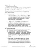
Recognizing that the CPU was now predominantly used for route calculations, Cisco renamed it
the route processor, and the auxiliary switching engine was renamed the switch processor. An all-
time high of 200,000 pps was achieved on the 7000 router performing autonomous switching (see
Figure 5-5).
Figure 5-5. Cisco 7000 Architecture
101
One additional refinement took place on the 7000 series. The silicon switch processor (also
known as the silicon switch engine, or SSE) is a hardware-accelerated alternative to the standard
switch processor. An SSE cache was precomputed on the route processor card and regularly
was dumped into the SSP. The result was more than 270,000 pps.
Optimum Switching
In 1995, Cisco introduced the 7500 series. Refinements relevant to switching included the
combination of both the route and the switch processors on a single card, and a new CyBus of
1.077 Gbit/s capacity that was backward-compatible with the cbus interface processors of the
7000 series.
A new route-cache mechanism, based on an m-trie lookup algorithm, provided switching capacity
similar to the 7000 series with SSP—around 270,000 pps. Operationally, however, it performed
the same role as autonomous switching: offloading switching functions from the Route Switch
Processor (RSP). Optimum switching is the default on the 7500 series interfaces.
Distributed Switching
With the introduction of the Versatile Interface Processor (VIP) cards, Cisco made the ultimate
step toward a peer multiprocessor architecture. Each VIP card contains its own MIPS r4600 RISC
processor, runs a mini-IOS kernel, and has configurable levels of SRAM and DRAM. Although the
VIP1 was available for a short time, most of the installed base consists of VIP2s. The distributed
features are targeted at the 7500 series (see Figure 5-6), but a VIP1 without distributed features
is supported in a 7000 platform equipped with an RSP7000 (combined RP/SP).
Figure 5-6. Cisco 7500 Architecture
102
Each VIP card participates in an interprocess communication system with the RSP over the
CyBus. IPC maintains an up-to-date copy of the RSP's fast switching cache on each VIP card,
enabling each to perform switching independent of the RSP, with the exception of the use of
packet memory.
Hence, within the constraints of the system bus, packet throughput is increased linearly with the
number of VIP cards installed in the router. Switching local to a VIP is performed at more than
120,000 pps, and between VIPs at more than 70,000 pps.
103
Netflow Switching
As discussed in Chapter 4, "Network Topology and Design," accounting of data traffic is not
only important for customer billing, but is a crucial part of traffic engineering. For example,
knowing the relative size of flows between routers in the network core can help you calculate the
most cost-effective topology and circuit size of the core network.
In terms of operation, Netflow switching is similar to the fast-switching cache: The first packet of
any flow is process switched and involves a routing table lookup by the CPU/Route Processor
(RP). Subsequent packets in the flow can be switched using a fast-cache lookup rather than an
expensive routing table traverse. In addition, on platforms capable of autonomous or optimum
switching, Netflow cache lookup and packet forwarding can occur without interrupting the RP.
The differences between Netflow and the fast-cache–based switching paradigms is the
information maintained in the cache, as well as the fact that, in Netflow switching, this information
can be periodically exported to collector hosts for further post-processing and analysis.
Per-flow information that is maintained by the Netflow cache includes the following:
• IP source and destination address
• Next-hop router address
• Input and output physical interfaces
• Packet and byte counts
• Start-of-flow and end-of-flow timestamps
• TCP/UDP source and destination application port numbers
• IP protocol (such as TCP, UDP, and so on)
• Type of service (indicates packet priority in multi-class service)
• TCP flags
• Source and destination autonomous system numbers
• Source and destination subnet masks
Other than the obvious accounting capabilities, Netflow switching improves performance in the
presence of complicated administrative filtering features, such as access lists. As with fast
switching, Netflow can operate in centralized or distributed switching mode. Distributed mode
supports the maintenance and exportation of the cache from individual VIPs.
Cisco Express Forwarding
Operational experience proves that the demand-cache mechanisms described previously did not
scale well in highly dynamic routing environments such as the Internet. Fast-switching caches
must generally be invalidated when there is a change in the routing table. Although route
holddown can prevent cyclic churn, rebuilding the cache is computationally expensive because
packets that initiate cache entries must be process-switched.
CEF resolves this problem by building and maintaining a forwarding information base (FIB) with
entries that include a one-to-one correspondence with entries in the IP routing table. Each entry
in the FIB points to an IP next-hop that exists in an adjacency table. The adjacency table contains
the information necessary for MAC-layer rewrites (see Figure 5-7).
Figure 5-7. Routing, FIB, and Adjacency Table Entries
104
NOTE
Adjacency information is the MAC-layer header to which a router must forward IP packets to
another device on the interface.
Unlike fast-cache entries, which are comprised of host routes only, CEF entries can include
hosts, subnets, or even supernets. In core-routing environments, the FIB table, therefore, may
actually be smaller than a demand-built fast-cache. The FIB is created immediately after router
boot-up.
105
CEF is able to run in centralized or distributed mode (see Figure 5-8). In distributed mode (see
Figure 5-9), a FIB and an adjacency database are maintained on each VIP card. As with DFS,
interprocess communication over the cybus is used to coordinate the distribution of the FIB table.
Figure 5-8. CEF Operation
Figure 5-9. dCEF Operation
106
With the introduction of the Gigabit Switch Router platform family, Cisco replaced the traditional
passive backplane used in earlier core products, such as the 7000 and 7500. An active and
extensible bit-slicing switching element comprised of a crossbar and associated control ASICs is
used to connect line cards for packet-forwarding purposes.
A central route processor performs systems management, routing, and forwarding table
calculations; and is responsible for distributing the CEF table to individual line cards. A separate
maintenance bus exists between line cards and the RP for bootstrapping and other diagnostic
and maintenance operations. However, large data transfers, such as CEF table downloads from
the RP to the line cards, occur through the switch fabric. Although the GSR operates with
distributed CEF tables, recursion is carried out at the RP rather than at individual line cards.
CEF has special handling of access lists and other per-interface intricate features that are
comparable, in performance terms, to optimum or autonomous switching. However, Netflow can
offer superior performance over CEF in the presence of complex access lists and other policy-
configuration features. In terms of accounting, CEF maintains basic per-prefix and adjacency
packet/byte counts. It also can be used with Netflow to provide more comprehensive accounting
functions and accelerated performance in the presence of access lists.
107
CEF also performs efficient per-packet or per-destination load sharing. Prior to CEF, per-packet
load sharing was always process-switched.
CEF is activated globally on routers, but both CEF and fast switching modes can be run
concurrently by disabling CEF on a per-interface/VIP basis. Concurrent operation is not
recommended, however, because this consumes resources for maintenance of both the FIB and
the fast switching cache.
Tag Switching
Tag switching aims to solve many of the problems facing large-scale networks. Among these are
the ever-increasing performance and scalability requirements; along with the need for service
differentiation, virtual private networks, and the means to easily control the path of traffic through
the network backbone. Tag switches—which may be dedicated tag-switching devices or IP
routers—forward packets based on a shim,which is an extra field on which to base a switching
decision. The shim is inserted between the Layer 2 and Layer 3 packet headers. In the case of
ATM, the shim may be the combination of the VPI and VCI.
A Tag Distribution Protocol (TDP) is used with standard IP routing protocols to distribute tag
information between switches within the network. Switching based on tags is extremely efficient
and is more readily implemented in hardware than the longest match lookups necessary for
forwarding based on IP destination addresses.
Tag switching is similar to CEF: A forwarding table is created, based on the contents of the IP
routing table. This Tag Information Base (TIB) is keyed based on incoming tags, and contains
entries of the form of outgoing tags, outgoing MAC-layer rewrites, and outgoing interfaces. As
with CEF, the TIB is prepopulated, based on the IP routing table rather than being built on a
packet-forwarding process on demand. Therefore, it scales well in dynamic routing environments.
Cisco's implementation of tag switching works efficiently with CEF because they share common
data structures and maintenance mechanisms.
Packets that arrive without a tag may be CEF or fast-switched, depending on the specific router
configuration. As with CEF, tag switching can operate in centralized or distributed mode on VIP-
capable platforms; it is enabled globally, but may be disabled on a per-interface/VIP basis (see
Figure 5-10).
Figure 5-10. Tag Switching
108
Routing and Forwarding
IP routers are typically capable of multiple routing processes, each of which maintains its own
RIB. These are either link-state protocols, such as IS-IS or OSPF; or distance-vector protocols,
such as RIP, IGRP, and BGP.
Each routing protocol may have multiple routes to the same destination, and the selection of the
best route by each protocol is normally determined on the basis of longest match, followed by
other routing protocol metrics. The per-protocol decision algorithm can be quite complex and can
depend on many locally configured variables that control routing policy.
109
Distance-vector routing protocols also may have incoming or outgoing policy filters—that is, they
may choose to ignore certain prefixes. Link-state protocols, however, do not generally have this
capability because they must flood consistent topological information. Some filtering is possible,
but if this is not part of the protocol itself (such as filtering between levels in IS-IS), it must be
used with extreme caution.
Populating the FIBs
IP prefixes from each routing process are inserted in the central forwarding information base
(FIB). This is the routing table used for actual packet forwarding. When there are two equal-length
prefixes from the different RIBs or different routing processes or protocols, an administrative
distance is applied to break the tie. This distance typically is applied to the whole routing
process—with the notable exception being BGP, which has different administrative distances for
external, internal, and locally generated routes.
Routes in the central FIB (which are only those actually chosen as the best routes for packet-
forwarding purposes) may be redistributed between routing protocols. This redistribution also may
be subject to local policy filters. Within a Cisco router, this central FIB is used for process
switching.
Improving FIBs: Fast IP Route-Lookup
With the staggering growth of the Internet and consequent demands on core Internet routers, the
field of fast IP route-lookup has been the subject of intense interest. Although route churn in the
Internet is relatively high, packet forwarding, rather than route-computation, is proving to be the
critical area requiring optimization. This signifies that lookup time is optimized at the expense of
routing table update time.
Route-lookup is the process of finding the best match between the destination IP address of a
packet and entries in the routing table. This may not be an exact match, but it is the most specific
supernet containing the destination IP address. This rule does not guarantee a unique choice if
non-contiguous subnet masks are used, which is one of many reasons their use is deprecated.
Most modern lookup techniques assume contiguous masking to achieve efficiency. In some
cases, the best route actually may be the default route.
Traditional approaches to route-lookup, such as those implemented in the BSD UNIX operating
system, employed tree structures. More recently, however, attention has been focused in three
areas: hardware-assisted lookups, using content addressable memories or caches; compression
techniques, allowing the routing table to fit in the high-speed cache of off-the-shelf processors;
and sophisticated hashing techniques. Cisco routers use a combination of these techniques,
depending on the switching mode employed.
As you read earlier in this chapter, the evolution of route-lookup and the resultant availability of
many lookup techniques means that modern routers may have a number of switching paths.
Each switching path maintains its own FIB, which is optimized for a certain type of
forwarding/switching paradigm, such as demand-built fast route-cache, or a special-purpose,
possibly hardware-assisted lookup mechanism.
Within a Cisco router, such as the c7500, these FIBs are used in a hierarchical manner. CEF is
an exception: A lookup failure in the CEF FIB results in a packet discard. When a lookup fails in
the lowest-level FIB, which is usually the fastest, switching of the packet is transferred to a
higher-level FIB, which is generally slower. Use of a particular FIB often can be configured on a
per-interface basis.
110
Switching with QoS
Traditionally, queuing of packets within IP routers has been first-in, first-out (FIFO). More recently,
Layer 3 quality of service features have been introduced to enable large-scale IP networks to
effectively handle a mix of best-effort, and mission-critical or time-sensitive applications. This is
typically achieved through congestion management and control algorithms implemented in a
packet scheduler associated with the outgoing interface.
The scheduler may perform a number of functions:
• Classifying packets assigns them particular priorities based on protocol type, and then
sends the packets in priority order. There is no minimum service level in priority queuing,
so lower-priority traffic can be locked out by higher-priority traffic.
• Custom queuing to ensure that packets match certain criteria (such as source address,
destination port, or IP precedence) is provided with a minimum service level. This is also
referred to as class-based queuing. Note that packets in the same class are still treated
as FIFO.
• Weighted fair queuing, which attempts to bound traffic latency, provides priority for
interactive traffic flows, and provides equitable treatment for large-volume (such as FTP)
flows. WFQ is supported in all switching modes, and can be used either with a default set
or a customer-supplied set of weights. Distributed WFQ requires CEF switching.
• Traffic shaping of outgoing packet streams occurs to meet agreed sustained and burst
rates. Traffic shaping can be applied, based on most fields in the IP header.
• Random Early Detection (RED) monitors the outgoing packet queue, and randomly
discards packets when user-configurable thresholds have been reached. When used with
TCP traffic, RED preempts congestion by backing off selected flows individually over a
period of time. This is preferable to a simple queue tail-drop, which results in multiple
TCP backoffs, and can induce cyclic congestion and "wave-like" link utilizations.
Distributed RED is possible with the distributed CEF switching mode.
• Committed Access Rate allows the maximum rate of traffic input or output on an interface
to be controlled. All packets are classified, based on conformity to or exceeding of
configured CAR; as a result, the packet can be dropped, or it can have its IP precedence
field adjusted. CAR requires CEF switching and may be run in distributed mode. Unlike
the other features described here, use of input CAR requires an input scheduler.
It is also possible to base routing decisions on fields other than the destination IP address. This
may be necessary due to QoS, security, or other policies. This cannot be accomplished through
an output scheduler, however, because the decision must be made prior to switching. An output
scheduler feasibly could route packets onto logical subinterfaces of a single physical interface.
Caching Technique Case Study
In previous sections about Cisco switching techniques, we discussed how fast switching is
performed, how cache is created from the routing table, and what information is kept in cache.
You might be wondering how the cache is populated. During the case study, the text discusses
what happens when a packet that must be fast-switched reaches the router.
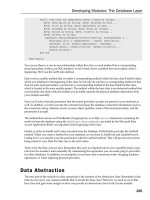
The cache is built from the routing table. In the scheme prior to CEF, the routing table is built
when the routing protocol injects routes. Before a packet is forwarded, a process performs a
lookup in the routing table and decides how the packet should be forwarded. Each entry in the
routing table for the network is considered. An example of entries in the routing table is shown
here:
111
Show ip route
150.150.6.0/24 [20/30] via 150.150.5.31, 00:00:23, Fddi2/0
150.150.0.0/16 [20/10] via 150.150.5.31, 00:20:23, Fddi2/0
171.68.0.0/16 [20/40] via 131.108.5.31, 01:50:2, Serial 0/0
171.68.0.0/16 [20/40] via 131.108.5.10, 01:05:2, Serial 0/1
10.10.10.1/32 [110/1572] via 131.108.5.10, 01:5:23, Serial 0/1
10.0.0.0/8 [20/10] via 131.1.1.1, 01:5:11, Ethernet 3/1
204.10.0.0/16 [20/40] via 150.150.5.31, 00:20:23, Fddi2/0
204.10.10.1/32 [20/30] via 150.150.5.31, 01:20:23, Fddi2/0
0.0.0.0/0 [20/20] via 150.150.5.31, 00:20:23, Fddi2/0
In the show ip route output shown above, the router has nine routing entries in the routing table.
The first two routing entries correspond with network 150.150.0.0. The first of the two is a subnet
entry 150.150.6.0/24, and the second correlates to the major network 150.150.0.0/16. The next
two entries correspond to major network 171.68.0.0/16. Following that, there are two entries for
the 10.0.0.0 network; the first is a host route to 10.10.10.1/32, and the second is an entry
corresponding to major network 10.0.0.0/8.
Next, there is a single entry for a CIDR block for 204.10.0.0/16. A host route to 204.10.10.1/32,
which is a network out of the CIDR block range, follows. The final entry corresponds to the default
route 0.0.0.0/0.
This example of an ip route explains how a Cisco router creates fast-switching cache entries,
which is shown in a show ip cache. We will begin by looking at the entries for network
150.150.0.0. The router has two entries in the routing table—one for the major network of
150.150.0.0/16 and one for the subnet of 150.150.6.0/24. Because the longest prefix mask for
this major net is /24 in the routing table, cache entries for any destination in 150.150.0.0 are
created as /24. If you send a packet to a destination of 150.150.8.1, the entry will be cached as
150.150.8.0/24, even though the major network of 150.150.0.0/16 covers the route for this
destination.
Now, consider the second case for the network 171.68.0.0/16. In this case, you have two equal
cost paths to the network. In this instance, /32 host entries are cache.
There is a misconception that load sharing is performed per session. In actuality, load sharing is
performed per destination. As an illustration, assume that a user wants to Telnet to 171.68.1.1.
The router will cache 171.68.1.1/32 via one of the interfaces. All future packets to this destination
will use this cache entry, so it will always be sent out the same interface. The host sending a
packet through the router will make a connection to 171.68.1.1 TCP port number 23. If another
user FTPs to the same host, 171.68.1.1, via this router, the router will use the newly created
cache entry.
Although both users are connecting to the same destination, each session is different, but all
packets take the same path that was created originally in the cache entry. This is the reason that
load sharing is per-destination and not per-session in fast switching. Now assume that another
user wants to connect to a different host on the same destination subnet. For example, if a third
user wants to connect to 171.68.1.2, this will cause a second cache entry to be created through
the second path, which is also a /32 entry. For this reason, cache entries during load sharing can
become very large.
112
The third entry in the routing table corresponds to network 10.0.0.0/8.The router has a /8 entry
and a /32 entry in the routing table. Each entry in the routing table would be cached for network
10.0.0.0/32, although there are only two entries in the routing table for the network 10.0.0.0/8. All
the entries for this network are created as /32. Remember from previous discussions that caching
is always done on the longest prefix in the routing table for the same major network.
TIP
A good practice for ISPs is to avoid receiving a /32 route from the Internet. ISPs should use an
access list to avoid routes with longer prefixes from being received from other ISPs or customers.
The only /32 routes an ISP should have in its routing table are routes from its own autonomous
system.
Note that Cisco routers still cache a classful entry for a CIDR route unless you are using CEF.
The routing table shown in the previous example has an entry of 204.10.0.0/16 and
204.10.10.1/32—in this case, the caching for all the CIDR networks would be performed as a
classful entry. If the router wanted to send a packet to the network 204.10.1.0/24, it would not
cache this route as a /16 because no explicit entry exists for network 204.10.1.0/24, and because
it is covered by 204.10.0.0/16.
The router also would not cache the route as a /32. Only entries for network 204.10.10.0 would
be cached as /32 because a host route of 204.10.10.1/32 exists in the routing table. No other
entry in the CIDR block of 204.10.0.0/16 would be cached as a /32.
Finally, the routes not found in the routing table will take the default route 0.0.0.0. All the entries
would be cached as a classful mask. If, for example, the router needs to send a packet to the
destination of 161.10.1.1, a cache entry would be created for network 161.10.0.0/16, not for
0.0.0.0/0.
Cache and Recursive Lookup
You can see from the previous discussion that, although this technique is efficient, it has
drawbacks, such as scalability problems. These problems do not affect the enterprise customer
because the networks are not changed rapidly and frequently, and because they do not carry
very large routing tables. Demand caching is a scalable method for the enterprise environment
because packet flow is not very dynamic. Cache deletion frees space in the memory as well.
ISPs, on the other hand, see the effect of caching on their networks because ISPs carry routes
from other networks, and they do not have control over the flapping. Therefore, routes appear
and disappear due to changes in another user's network. In addition, most of the routes in the
ISP environment are BGP-derived, so the next hops are not directly connected. For a router to
resolve the non-connected next hop, it must resolve this recursive lookup during the cache-
creation or during process switching. This can overload the router.
Cache entries also are aged from the cache table periodically (every minute), which contributes to
cache trashing.
For example, the next hop is not directly connected in the following routing entry for BGP. This
configuration shows the IP route for an IBGP-learned route:
113
Routing entry for 200.200.200.0/24
Known via "bgp 2", distance 200, metric 0
Tag 1, type internal
Last update from 171.68.181.1 00:45:07 ago
Routing Descriptor Blocks:
* 171.68.181.1, from 150.150.3.11, 00:45:07 ago
Route metric is 0, traffic share count is 1
AS Hops 1
The next hop in this case is 171.68.181.1, which is not a connected route. The router before it
forwards the packet to destination 200.200.200.0/24 and must resolve the next hop. The router
first must search the routing table for network 200.200.200.0/24, and then must perform a lookup
for the next hop: in this case, 171.68.181.1. Then, the router must find the connected interface
that will be used to forward the traffic toward the next hop and, ultimately, to the destination. This
is apparent in the show ip route output for the next hop:
C7000-2B#sh ip ro 171.68.181.1
Routing entry for 171.68.181.0/24
Known via "eigrp 200", distance 90, metric 284160, type internal
Redistributing via rip, eigrp 200
Last update from 171.68.173.13 on Ethernet0/0, 00:16:59 ago
Routing Descriptor Blocks:
* 171.68.173.13, from 171.68.173.13, 00:16:59 ago, via Ethernet0/0
Route metric is 284160, traffic share count is 1
Total delay is 1100 microseconds, minimum bandwidth is 10000 Kbit
Reliability 255/255, minimum MTU 1500 bytes
Loading 1/255, Hops 1
After the router has discovered the connected interface toward the next hop, the router creates
the cache entry, as seen in the following entry:
Prefix/Length Age Interface Next Hop
200.200.200.0/24 00:06:43 Ethernet0/0 171.68.173.13
Since this type of recursive lookup during major churns is not successful in the ISP environment,
Cisco created Express Forwarding for ISPs.
Populating Cisco Express Forwarding
CEF has two major components: the forwarding information base (FIB) and the adjacency
database. The FIB is the lookup table that the router uses to make destination base-switching
decisions during CEF operation. This table is almost an exact copy of the routing table. (The
FIB/CEF table does not carry administrative distances and metrics). When the routing table
topology is changed in the network, the routing table is updated and the changes are immediately
reflected in the CEF table.
114
Consider the same entries discussed in the last section. The routing table router contains the
following entries:
150.150.6.0/24 [20/1] via 150.150.5.31, 00:00:23, Fddi2/0
150.150.0.0/16 [20/10] via 150.150.5.31, 00:20:23, Fddi2/0
171.68.0.0/16 [20/0] via 131.108.5.31, 01:50:2, Serial 0/0
171.68.0.0/16 [20/0] via 131.108.5.10, 01:05:2, Serial 0/1
10.10.10.1/32 [110/1572] via 131.108.5.10 01:5:23 Serial 0/1
10.0.0.0/8 [20/10] via 131.1.1.1 01:5:11 Ethernet 3/1
204.10.0.0/16 [20/0] via 150.150.5.31, 00:20:23, Fddi2/0
204.10.10.1/32 [20/0] via 150.150.5.31, 01:20:23, Fddi2/0
0.0.0.0/0 [20/0] via 150.150.5.31, 00:20:23, Fddi2/0
Unlike the demand cache, in which the router created the cache entry on the longest prefix for the
network, CEF copies the complete routing table in the cache.
Consider the case of the routing entries for network 150.150.0.0. In this case, the router has two
entries for network 150.150.0.0/16 and 150.10.6.24. Unlike in the demand cache, if the router
wants to send a packet to subnet 150.150.8.0/24, it will not create an entry based on the longest
prefix. Instead, it will use the 150.150.0.0/16 entry.
Next, consider the case of network 171.68.0.0/16, in which the router has two equal-cost paths.
Prior to CEF, the router had to maintain the /32 cache for per-destination load balancing. With
CEF, the load sharing is now performed on the pair of source and destination caches. In our
example, when the router wanted to do a per-packet load, it had to process-switch the packets
because fast switching did not support per-packet load sharing.
With CEF, you can achieve per-packet load sharing, but the default is per-destination load
sharing. Per-destination uses both source and destination for load sharing. Per-packet is more
useful when the bulk of the traffic is destined for one host, such as a Web server. To balance the
traffic from multiple users to the same destination with per–packet load sharing, the router sends
packets to the same destination on different paths, as shown here:
Prefix Next Hop Interface
0.0.0.0/0 150.150.5.31 FDDI2/0
150.150.0.0/16 150.150.5.31 FDDI2/0
150.150.6.0/24 150.150.5.31 FDDI2/0
171.68.0.0/16 131.108.5.31 Serial 0/0
171.68.0.0/16 131.108.5.10 Serial 0/1
10.10.10.1/32 131.108.5.10 Serial 0/1
10.0.0.0/8 131.1.1.1 Ethernet 3/1
204.10.0.0/16 150.150.5.31 FDDI2/0
204.10.10.1/32 150.150.5.31 FDDI2/0
Again, in the case of network 10.0.0.0, the router has two entries: one for network 10.10.1.1/32
and another for network 10.0.0.0/8. Unlike the demand cache, no additional entries are created
on the longest prefix.
115
Previously, classful entries were created for the CIDR route, and /32 entries were created for
network 204.10.10.0. This is a marked reduction of the number of entries created for the CIDR
route. Rather than creating 254 entries for the CIDR route plus 254 entries for the major net
route, the router now needs to create only two entries.
In the demand-caching model, the router creates entries for all the networks to which it is sending
packets on the classful mask for the default route, as discussed earlier. With CEF, an entry is
created for the default network.
The next component of FIB is the MAC-layer rewrite, which is completed via the adjacency table.
Network nodes are considered adjacent if they can be reached directly. CEF creates an
adjacency table for Layer 2 information.
The adjacency table maintains Layer 2 next hop addresses for all the FIB entries. It is populated
as the adjacencies are discovered; each time the adjacency entry is created, a link-layer header
for that adjacency node is precomputed and stored in the adjacency table. After the route is
determined, it points to a next hop and to the corresponding adjacency. This route is
subsequently used for encapsulation during the CEF switching of packets.
Adjacency resolution is useful for load sharing. When a router is configured for load sharing, a
pointer is added for the adjacency corresponding to the next hop interface for each resolved path.
Recursive Lookup and CEF
In recursive lookup, the next hop for IBGP routes is not directly connected. This problem must be
resolved, as shown in the following output of show ip route for an IBGP-learned route:
Routing entry for 200.200.200.0/24
Known via "bgp 2", distance 200, metric 0
Tag 1, type internal
Last update from 171.68.181.1 00:45:07 ago
Routing Descriptor Blocks:
* 171.68.181.1, from 150.150.3.11, 00:45:07 ago
Route metric is 0, traffic share count is 1
AS Hops 1
In this case, the next hop, which is 171.68.181.1, is not directly connected, so this route must be
learned via IGP. As shown, this route is learned via Enhanced IGRP:
Routing entry for 171.68.181.0/24
Known via "eigrp 200", distance 90, metric 284160, type internal
Redistributing via rip, eigrp 200
Last update from 171.68.173.13 on Ethernet0/0, 00:16:59 ago
Routing Descriptor Blocks:
* 171.68.173.13, from 171.68.173.13, 00:16:59 ago, via Ethernet0/0
Route metric is 284160, traffic share count is 1
Total delay is 1100 microseconds, minimum bandwidth is 10000 Kbit
Reliability 255/255, minimum MTU 1500 bytes
Loading 1/255, Hops 1
116
Notice the BGP entry for network 200.200.200.0. The next hop is not directly connected; so to
reach the next hop, the router must find the connected interface used to reach 171.68.181.1. By
reading the show ip route for 171.68.181.1, it has learned Enhanced IGRP on Ethernet 0/0. The
connected next hop to reach 171.68.181.1 is 171.68.173.13, which is the directly connected next
hop. CEF resolves this issue by attaching the BGP route to the immediately connected next hop.
In this case, it will create the following CEF entries:
Prefix Next Hop Interface
171.68.181.0/24 171.68.173.13 Ethernet0/0
171.68.173.0/24 Attached Ethernet0/0
200.200.200.0/24 171.68.173.13 Ethernet0/0
Different Types of Adjacencies
There are several types of adjacencies:
• Null adjacency
Packets destined for null-interface are dropped. This is used for dropping packets to
unknown destinations. It can be used as an effective form of access filtering.
• Glean adjacency
When a router is connected to a subnet, the FIB table maintains a prefix for the subnet
rather than for each individual host. This subnet prefix points to a glean adjacency. When
a packet must be forwarded to a specific host, the adjacency database is gleaned for the
specific prefix.
Output of show ip cef glean appears as follows:
Prefix Next Hop Interface
216.179.253.128/25 Attached FastEthernet8/0
219.1.169.220/30 Attached FastEthernet9/0
219.18.9.124/30 Attached FastEthernet2/0
219.18.9.136/30 Attached FastEthernet2/0
219.18.84.128/26 Attached FastEthernet5/0
• Punt adjacency
Features that require special handling or are not yet supported with CEF are forwarded to
the next switching layer for handling.
• Drop adjacency
Packets are dropped, but the prefix is checked.
117
These two examples provide you an opportunity to see how the cache is populated by demand
cache, which is used for fast switching, as well as how CEF populates the cache.
Summary
The fundamental roles of routers are route-computation, packet scheduling, and forwarding.
Router architecture has evolved through three generations, from a shared bus central CPU, to
multiple peer-line cards connected by an intelligent switching fabric. With this evolution, the Cisco
core product line has evolved from central CPU-orientated process switching through the use of a
fast switching cache, to distributed CEF.
Routers may compute multiple RIBs, each associated with a particular routing protocol (OSPF,
Enhanced IGRP, RIP, BGP, or IS-IS) or process. Similarly, routers also may contain multiple
FIBs, each associated with a particular switching path (process, fast, CEF, or TAG). Improvement
in route-lookup methodology, together with the cheaper availability of low-cost memory, has
played a major part in increased packet throughput. These concepts are summarized in Figure
5-11.
Figure 5-11. Router Routing, Switching, and Scheduling Overview
118
119
Increasingly, network operators are calling for sophisticated, yet scalable accounting, security,
packet scheduling, and traffic-engineering features. New switching techniques, such as CEF,
TAG, and Netflow, address these needs. The choice of switching mechanisms depends on the
placement of the router within the network architecture: The accounting and security features of
Netflow and CEF are generally performed at the perimeter, whereas the performance of CEF,
and the traffic engineering and performance of TAG are aimed at the core.
Scalable congestion control and management algorithms, such as RED, CAR, and WFQ, will be
critical components of modern high-performance routers. Again, the roles of routers vary,
depending upon their position within the network architecture. Classification of packets will be a
function of the routers on the perimeter of the network, and the core routers will focus on highly
scalable packet scheduling.
Review Questions
1:
When you see a cache ager running on a network, should you be alarmed?
2:
Why do you see so many /32 entries on a network, and what can you do to
prevent these?
3:
Do you cache a CIDR route?
4:
How do you enable optimum switching?
5:
In what situation is it wise to disable fast switching?
6:
What is CEF?
7:
Will cache ager run with FIB?
8:
If CEF does not process-switch, how does it receive the MAC-layer information?
9:
What are adjacencies?
10:
Does FIB support load sharing?
11:
Does CEF support access lists?
Answers:
1:
When you see a cache ager running on a network, should you be alarmed?
A:
No. This is normal behavior for demand caching. Unused entries are aged out
every minute.
2:
Why do you see so many /32 entries on a network, and what can you do to prevent these?
A:
Block/32 routes in your routing table from other autonomous systems. You
12
0
might also perform load sharing.
3:
Do you cache a CIDR route?
A:
No. Cache at the longest prefix or the classful network boundary for demand
cache, if there is a CIDR or a default route.
4:
How do you enable optimum switching?
A:
It is the default on RSP processors. Disable it with no ip route-cache
optimum because it is an interface subcommand.
5:
In what situation is it wise to disable fast switching?
A:
Disable fast switching when you have a high-speed interface feeding a slower
link and enough CPU power is available. This can be successful for enterprise
environments, but not for an ISP.
6:
What is CEF?
A:
CEF assists in making forwarding decisions; it is an exact copy of the routing
table and performs well for large routing-table environments.
7:
Will cache ager run with FIB?
A:
No. CEF does not create entries on demand; it copies the routing table.
8:
If CEF does not process-switch, how does it receive the MAC-layer information?
A:
CEF receives its MAC-layer information via adjacencies.
9:
What are adjacencies?
A:
Two nodes are considered adjacent if they can reach each other via a single hop
across a link. The adjacency database is a table of connected nodes, each with
information about the L2 MAC rewrite.
10:
Does FIB support load sharing?
A:
Yes. It supports load sharing, based on both per-packet and per-destination.
11:
Does CEF support access lists?
A:
Yes. Both inbound and outbound access lists are supported.
For Further Reading…
Bennett, G. Designing TCP/IP Internetworks. New York, NY: John Wiley and Sons, 1997.
Degermark, Brodnik, Carlsson, and Pink. Small Forwarding Tables for Fast Routing Lookups.
France, Proc ACM SIGCOMM 97, September 1997.
121
Keshav, S. An Engineering Approach to Computer Networking. Reading, MA: Addison-Wesley,
1997.
Keshav and Sharma. "Issues and Trends in Router Design." IEEE Communications Magazine,
(May 1998).
Kumar, Lakshman, and Stiliadis. "Beyond Best Effort: Router Architectures for the Differentiated
Services of Tomorrow's Internet." IEEE Communications Magazine, (May 1998).
122
Chapter 6. Routing Information Protocol
This chapter provides an overview of the Routing Information Protocol (RIP), including the
following topics:
Overview of RIP
This section discusses RIP's basic functions, its limitations, and the algorithm it uses.
Introduction to the distance vector protocol
In this section, we explain the algorithm based on Bellman Ford, and explore how the algorithm is
executed, and how information is passed along the path.
Fundamentals of RIP operation
This section explains the basics of RIP, how routes are calculated, and how information is
propagated.
Discontiguous networks
In this section, we discuss disconnected networks and how RIP behaves when parts of a major
network are disconnected, and we offer suggestions on how to employ them.
Overview of RIP
RIP is a distance vector protocol that uses the Bellman Ford algorithm to compute the shortest
route to the destination. RIP was originally designed for Xerox PARC and was used in Xerox
Network Systems (XNS). It then became associated with TCP/IP and the UNIX system. The
protocol is one of the first dynamic routing protocols used in the Internet. It was developed as a
method of passing reachability information between routers and hosts.
Each entry in a RIP table contains a variety of information, including the ultimate destination, the
next hop toward the destination, and the metric to reach the destination. The metric indicates the
distance in number of hops to the destination. RIP maintains the best route to the destination, so
when new information provides a better route, this information replaces the previous route in the
table.
Although RIP is still a widely used protocol, it has several restrictions, including a 15-hop
maximum. (The sixteenth hop has a special meaning in RIP, as you will discover in Chapter 7.)
RIP also lacks support for variable-length subnet masking or supernetting. Currently, the Internet
uses addresses that appear to be part of the class A network. RIP Version 1 will be incapable of
utilizing these addresses because of its classful behavior. For these reasons, RIP has been
declared a historic document in RFC 1923.
RIP is greatly hindered by its inability to consider real-time parameters, such as bandwidth, delay,
or load. Consider the network in Figure 6-1. Here, router R1 learns about network 131.108.10.0
from two routers: R2 and R3. The route is advertised by R3 to network 131.108.10.0 with one
hop, and router R2 advertises it with two hops. Because RIP is not concerned with the speed of
the links between the routers, it chooses R3 to reach the destination, even though the link speed
via R2 is approximately 30 times faster. Naturally, this decision is extremely undesirable.
123
Figure 6-1. Suboptimal Path Taken by RIP on Number of Hops
With a hop-count limit of 15, any destination greater than 15 hops is considered unreachable. The
RIP hop count greatly restricts its use in a large network. However, the restriction does prevent a
count to infinity problem from causing endless routing loops.
The count to infinity problem is shown in Figure 6-2. Here, router R1 can reach network A with a
hop count of 1, and it advertises this route to router R2. Realizing that it can reach network A with
a hop count of 2, R2 then sends this information back to R1. Now, R1 loses its connection to
network A, and sees that it can reach network A via R2. As R2 is advertising network A with two
hops, router R1 says that it can reach network A with three hops. Because R2's next hop to
destination A was R1, R2 sees that R1 can reach destination A with three hops. R2 then changes
its hop count to four. This problem continues indefinitely, unless some external boundary
condition is imposed. This boundary condition is RIP's maximum hop count of infinity, which is the
sixteenth hop.
Figure 6-2. Count to Infinity
124
Three additional issues with regard to RIP also must be addressed: holddown, split horizon, and
poison reverse:
• Holddowns prevent regular update messages from inappropriately installing a route that
has become defective. When a route is defective, neighboring routers detect it, and then
calculate new routes. The routers send out routing update messages to inform their
neighbors of the route changes. This update might not arrive to all the routers at the
correct time, however, which causes some routers to choose an incorrect path. A
holddown tells routers to suppress any changes that might affect recently removed routes
for some period of time. This period is greater than the time it takes to update the entire
network with a routing change.
• A split horizon is derived from the fact that it is never useful to send information about a
route back to the direction from which it came. For example, revisit Figure 6-2. Router
R1 advertises routes from network A to router R2. Thus, it is unecessary for router R2 to
include this route in its update back to R1 because R2 learned this route from R1 and
because R1 is closer to the destination. The split horizon rule states that R2 should strike
this route from any update sent to R1. Split horizon prevents looping problems between
nodes.
• Poison reverse updates the sending neighbor about the route it has sent with an infinity
metric. For example, in Figure 6-2, router R2 sends the route back to R1 with an infinity
metric. Poison reverse updates also help prevent routing loops.
One of RIP's many drawbacks is that it does not support variable-length subnet masking. Classful
in nature, version 1 packets do not carry mask information. If an update is received about a
subnet of the connected network, this version infers that the mask is the same as that of
connected interfaces on that network. The router will always summarize when crossing a network
bound at a natural classful mask.
Consider the network shown in Figure 6-3. When router R1 sends updates about network
140.10.10.0/24 out of serial interface, it sends updates at a classful mask of 14.10.0.0/16
because the updates travel across a different major network. When R2 receives this update, it
ignores this route because one of its interfaces is connected to the same major network.
Figure 6-3. RIP and Discontiguous Networks