CCIE Professional Development Large-Scale IP Network Solut phần 6 ppsx
Bạn đang xem bản rút gọn của tài liệu. Xem và tải ngay bản đầy đủ của tài liệu tại đây (659.86 KB, 49 trang )
247
Route Summarization
IS-IS does not include the concept of filtering, so link-state protocols do not have the liberty of
filtering information when they are propagated. The only location in which filtering could occur is
at the point of origin. To filter out propagation of a redistributed route in IS-IS, you can use the
summary-address command to limit the routes from propagating L1 and L2. For L1, the router
summary-address command is used to summarize external routes only. For L2, the summary-
address command is used for summarizing external routes as well as L1 routes.
Scaling IS-IS
Currently, IS-IS is being used as an IGP by some of the largest ISPs. In most cases, a well-
defined ISP network should not have a large IGP routing table, but due to extensive redundancy,
scaling does become a problem. In addition, even if the IGP has a strong addressing structure,
sometimes it must find specific routes to the next hop according to strict policy requirements. For
this reason, route summarization is not always possible.
Experience in working with IS-IS has provided some insight that may be useful to you. One of the
key things to remember is that Cisco defaults to both the level 1 and level 2 routers because all
the level 2 routers must route within their area. In addition, the router cannot distinguish whether it
is a transit IS for interarea traffic. This is the reason Cisco runs L1 and L2 as the default mode.
Running L1 and L2 throughout the network is less scalable because the router must maintain two
separate databases and must run multiple SPFs. This L1 and L2 model enlarges the backbone
more than necessary, so it is highly recommended that you configure L1 as the default when
possible, especially when you are running IS-IS for IP.
For scaling any large-size IP network, the address layout is very critical. The address scheme
must be laid out so that an L1 and L2 router can summarize and send a single route to the
backbone for the level 1 area. If the network is small, everything can be placed into one area,
leaving provisions for the expansion of a multiarea environment for future growth.
IS-IS Over NBMA Networks
The behavior of link-state protocols is different when handling non-broadcast multiaccess
networks. In this situation, a difference always exists between physical and logical topology. For
broadcast networks, for example, a pseudonode is created and is flooded with the ID set to the ID
of the DIS. The broadcast model will also be successful in the frame or ATM cloud, as long as all
the virtual circuits are operating properly. When a PVC breaks down, forwarding and routing is
blackholed.
A router that loses its virtual circuit to the DIS will try to become the DIS. Other routers will send
the ID of the actual DIS to this router. The router that has lost its virtual circuit to the DIS cannot
send packets because the database loses synchronization when there is no connection to the
DIS.
Although this router has just lost its connection to the DIS, it still has operational PVCs to other
routers. Yet, because it lacks completed data base synchronization, it cannot use those PVCs to
route traffic through other routers. If the database is not completely in sync, the routes are not
installed in the routing table.
One model that could be applied here is the point-to-point subinterface. An IP address could be
configured on these interfaces. However, this would waste a considerable amount of address
24
8
space. Therefore, the best approach is to apply an unnumbered point-to-point network because it
does not have point-to-multipoint, as in OSPF.
The point-to-point model does not have blackholes, but it does have a problem with flooding.
When a router receives an LSP, it should flood the LSP to all the neighbors except the one from
which it learned of the LSP.
This could become a serious problem in a large mesh environment. A single router can receive
the same LSP (n–1)
2
times! To solve this issue, Cisco employs a feature called interface
blocking, with which you can configure certain interfaces to avoid flooding the LSP. This should
be performed with redundancy in mind, so that all the routers on the cloud receive the LSP. This
feature is discussed in more detail in Chapter 9, "Open Shortest Path First."
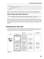
Figure 10-6 shows the flood storm that is created on a full meshed point-to-point subinterface.
The storm is created by the re-flooding of the LSP on the same physical interface, but having
different logical interfaces with the same set of neighbors.
Figure 10-6. LSP Flood Storm on Full Meshed Point-to-Point Interfaces
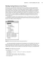
Basic IS-IS Configuration
To perform basic IS-IS configuration, the router process for IS-IS is defined first, and then an
NSAP address is assigned to the router. Figure 10-7 depicts a sample network in which router B
is a level 1 and level 2 router, and router A is only a level 1 router.
Figure 10-7. Simple Network Setup for IS-IS
249
The configuration of router B is as follows:
hostname router B
clns routing
interface Pos1/0/0
ip address 10.10.1.1 255.255.255.0
ip router IS-IS MKS
IS-IS circuit-type level-2
interface atm 2/0/0
ip address 131.108.1.1 255.255.255.0
ip router IS-IS MKS
IS-IS circuit-type level-1
router IS-IS MKS
net 39.00001.0000.0000.0001.00
As you can see in Figure 10-7, router A does not need to be a level 2 router because it only has
to create a single database.
The configuration of router A is as follows:
hostname router A
clns routing
interface atm 2/0
ip address 131.108.1.2 255.255.255.0
ip router IS-IS MKS
router IS-IS MKS
net 39.0001.0000.0000.0002.00
is-type level-1-only
The basic configuration for IS-IS is simple, as long as the router level is undefined. By default, the
router runs both level 1 and level 2. If the router is left at the default behavior (say, it is an L1 and
L2 router), you must define the circuit type that the interface is running by defining the level type,
250
as for router B. If you define the IS type under the router IS-IS command, however, the router
becomes confined to that level only, as is the case for router A.
The net command assigns a unique NSAP address to the router. This address is assigned per
router, not per interface; in this case, the first three bytes are area addresses and 39.0001 is the
area address. The next six bytes comprise the system ID 0000.0000.0002 (router A) and the last
byte is the N selector, which will be 00 for the router. For this reason, this NSAP address is a
NET.
The spf-interval Command
By default, the SPF algorithm runs at least every five seconds, under stable network conditions,
even though network events such as adjacency changes could trigger immediate SPF runs.
Running SPF on a very large LS database requires tremendous processor resources, so a high
frequency of runs could be disastrous to the router and the network. The spf-interval command
adjusts the frequency at which SPF runs. This command was set for periodic intervals, and SPF
runs at 30 seconds.
The sh IS-IS spf-log command displays how frequently the SPF process has run and is an
indication of the event trigger. The configuration would be the following:
RTR-B#sh IS-IS spf-log
Level 1 SPF log
When Duration Nodes Count Triggers
00:25:27 8 4 1 PERIODIC
00:18:09 12 5 2 NEWLSP TLVCONTENT
00:10:27 8 5 1 PERIODIC
Level 2 SPF log
When Duration Nodes Count Triggers
00:40:35 8 3 1 PERIODIC
00:25:35 8 3 1 PERIODIC
00:18:17 8 3 1 TLVCONTENT
00:10:34 8 3 1 PERIODIC
The IS-IS metric Command
IS-IS is limited because its metric has only six bits. This means that the value of an individual
metric can range only from 0 to 63. The total length of a path between two ISs can be 1023
maximum. You should consider the metric in advance. The default value is assigned to be 10,
independent of the bandwidth for all types of links and for both level 1 and level 2. The interface
metric can be modified for each level independently. Configuration for level 1 metric is as follows:
Hostname router B
Interface serial 0
ip address 131.108.1.1 255.255.255.0
ip router IS-IS MKS
IS-IS circuit-type level-1
IS-IS metric 30 level-2
251
By defining the level with the metric command, the level 2 metric is 30 for this serial interface.
The log-adjacency-changes Command
The log-adjacency-changes command is very useful because it tracks changes. In link-state
protocols, it is very important to keep track of the neighbors. This command identifies any
changes to the adjacencies and link flaps.
The configuration for router B here is as follows:
hostname router B
router IS-IS MKS
net 39.0001.0000.0000.0001.00
log-adjacency-changes.
The output of this command is:
routerB # sh log
%CLNS-5-ADJACENCY: IS-IS: Adjacency to 0000.0000.0001 (ethenet0)
IS-IS and Default Routes
The purpose of the default route in any routing protocol is to forward traffic to destinations that are
not in the router's routing table. It is not possible for all the routers in a network to have full
Internet routes. For this purpose, routers without full routes to all the destinations forward traffic to
the default originating router.
Level 1 routers never maintain information about any destination that is outside their area, so all
level 1 routers merely send packets to the nearest level 2 router for any destination outside their
local area.
The default-information originate command is used with level 2 routers for sending traffic to
destinations not found in the local routing table. This command is used to send a default route in
the backbone, and it creates an external entry into the L2 LSP. Unlike OSPF, this command does
not require a default route to be present in the router that is originating the default route.
If you compare this command with the OSPF default-information command, it behaves similar
to the way that the default-information originate always command behaves in OSPF. This
means that, regardless of the default route's presence in the routing table of the originating
router, the command still propagates a default route.
IS-IS and Redistribution
A route whose source does not originate from the IS-IS domain is treated as an external route.
Therefore, a separate TLV is defined for IP external ratability information. These external routes
can be redistributed into both level 1 and level 2 as external routes.
252
Metrics for external routes can be redistributed, just as they can for both internal and external
metrics. In a tie-breaking situation, the internal is preferred over the external:
router IS-IS MKS
net 39.0001.0000.0000.0001.00
redistribute static ip metric 30 level-1-2
ip route 55.1.0.0 255.255.0.0 Null0
ip route 55.2.0.0 255.255.0.0 Null0
IS-IS and Summarization
Level 1 router summarization is done only for external routes (redistributed routes from other
protocols) because the level 1 router does not receive any routes from the level 2 routers. As
such, there is no need to summarize routes from level 2 routers—you can summarize both level 1
and external routes in level 2.
External routes can be summarized only at the redistributing router. After the LSP is originated, it
cannot be summarized. Summarizing of external routes in level 1 routers is performed as follows:
router IS-IS MKS
net 39.0001.0000.0000.0001.00
summary-address 131.108.0.0 255.255.0.0 level-1
redistribute static ip metric 30 level-1
ip route 131.108.0.0 255.255.0.0 Null0
You can also summarize routes from level 1 into the backbone:
router IS-IS MKS
net 39.0001.0000.0000.0001.00
summary-address 131.108.0.0 255.255.0.0 level-2
This configuration is for summarization of the links of a level 1 area into a level 2 area.
Summary
IS-IS is a link-state protocol based on the OSI Intradomain Routing Protocol, and is designed for
use with the ISO protocol. It can support pure IP environments, pure OSI environments, and
multiprotocol environments. There are four packet types in IS-IS: hello, LSPs, CSNP data units,
and PSNP data units.
Link-state protocols (LSPs) are based on neighbor relationships. Every router advertises the cost
and state of its links. There are four LSP processes: receive, update, decision, and forwarding.
253
LSPs are flooded to provide the routers a consistent view of the network. Flooding and
synchronization are performed via CSNP, PSNP, SSN, and SRM bits.
There are two levels of hierarchy in IS-IS. In level 1, routers have full knowledge of all the links in
their area. For any destination outside their area, they route to the closest level 2 router. Level 2
routers form the backbone of IS-IS.
By default, all Cisco routers are configured as both L1 and L2. Maintaining a database for both
levels is not scalable, so route summarization is not always possible. The router should be
configured as a single level only, wherever possible. For scaling a large IP network, the address
scheme must be laid out so that L1 can summarize and send a single route to the backbone from
the level 1 area.
LSPs behave differently in NBMA networks. There is always a difference between physical and
logical topology. To maintain synchronization of the database, a point-to-point interface is used.
However, there can be flooding as a result, which is a major problem in a large mesh
environment. This problem is addressed with an interface-blocking feature in Cisco routers. By
following the configuration advice in this chapter, you should be able to successfully operate IS-IS
in your network.
Review Questions
1:
What is the difference between an NSAP and a NET?
2:
Why would you want multiple NETs on one box?
3:
How many bits are reserved for the metric in IS-IS?
4:
When is a non-pseudonode LSP generated?
Answers:
1:
What is the difference between an NSAP and a NET?
A:
An NSAP with an n-selector of 0 is called a NET.
2:
Why would you want multiple NETs on one box?
A:
You can use multiple NETs while in the process of merging or splitting areas.
3:
How many bits are reserved for the metric in IS-IS?
A:
Six bits are reserved, so the metric cannot be larger than 63.
4:
When is a non-pseudonode LSP generated?
A:
A non-pseudonode LSP represents a router and includes the ISs and the LANs
attached to that router.
254
For Further Reading …
Marty, Abe. "Introduction to IS-IS." Cisco Internal Document.
Previdi, Stefano. IS-IS Presentation. 1998.
Smith, Henk. IS-IS Personal Communication. 1999.
Smith, Henk. IS-IS Presentation. 1997.
255
Chapter 11. Border Gateway Protocol
Earlier chapters in this book described interior routing protocols used predominantly for routing
within autonomous systems. This chapter discusses the Border Gateway Protocol (BGP), which
is predominantly used for routing between autonomous systems.
The approach of this chapter is similar to the earlier chapters on routing protocols: It begins with a
bird's-eye view of how the protocol works and then dives straight into the details of its various
messages, routing information, and states. Next, we explore the scalability features of Cisco's
implementation, and finally, we provide general configuration tips for large-scale networks. This
chapter covers the following issues in relation to BGP:
Fundamentals and operation of BGP
In this section, you will read about the basic operation and application of BGP. The text describes
the application of the protocol within and between networks.
Description of the BGP protocol
This section examines the protocol at the packet level. You will learn the details and purpose of
BGP open, update, notification, and keepalive messages; and will discover how the various Cisco
configuration commands modify the behavior of the protocol. Newer features of BGP, such as
capability negotiation and multiprotocol extensions, are also included in the discussion.
BGP's finite state machine (FSM)
BGP has an eight-state FSM. This section describes the purpose of each state, how Cisco's
implementation moves from one state to the next, and how this movement between states may
be modified by configuration commands.
The routing policy and the BGP decision algorithm
Understanding the BGP decision algorithm is the key to understanding the protocol and its
operation. This section describes the algorithm specified in the BGP RFC, and discusses the
optimizations and extensions included in the Cisco implementation. Configuration commands that
can be used to tune the behavior of the decision algorithm are also described.
Scalability features
This section describes the use of peer groups, route-reflectors, and confederations to scale BGP
architectures.
Large network BGP configuration
This section examines specific configuration issues for large networks. The discussion includes
BGP synchronization, authentication, automatic route summarization, logging, dampening, and
the use of peer groups and loopback addresses. It concludes with the development of a BGP
configuration "stencil" for large networks.
The chapter concludes with a case study that examines the overall BGP architecture of a large
service provider network.
256
Introduction to BGP
BGP was originally designed for routing between major service providers within the Internet, so it
is considered an exterior routing protocol. A worthy successor to the now-obsolete Exterior
Gateway Protocol (EGP), BGP is the "glue" that holds the modern Internet together. It has
assumed that role since version 4 of the protocol (BGP4), which was deployed in 1993. Earlier
versions of BGP—notably BGP3—were used on the NSFNET in the early 1990s.
As a protocol, BGP requires a great deal of manual configuration. This, along with its detailed
design and considerable testing exposure on the Internet, has led to a stable and highly scalable
implementation of the protocol. The level of BGP operational expertise is increasing, and
modifications to the protocol to support Virtual Private Networks (VPNs) and even voice-call
routing, are on the horizon.
Fundamentals of BGP Operation
BGP is structured around the concept that the Internet is divided into a number of Autonomous
Systems (ASs). Before you learn how the protocol operates, you should become familiar with
ASs.
An Autonomous System (AS) is a network under a single administration, identified by a single
two-byte number (1–65536), which is allocated by the InterNIC and is globally unique to the AS.
Within an AS, private AS numbers may be used by BGP, but they must be translated to the
official AS prior to connectivity with the Internet.
An AS is essentially a network under a single administrative control, and it may be categorized as
a stub, multihomed, or transit AS. A stub AS is a network that connects to a single Internet
service provider and does not generally provide transit for other ASs. A multihomed AS connects
to more than one ISP. A transit AS is the ISP itself. In other words, it provides connectivity
between other ASs.
Figure 11-1 shows this arrangement. Stub AS-A reaches other destinations on the Internet
through its transit provider, ISP-C. Stub AS-E reaches all Internet destinations through its transit
provider, ISP-D.
Figure 11-1. Stub, Multihomed, and Transit ASs
Transit providers must either provide connectivity to all other transit providers in the global
Internet, or purchase that connectivity through a higher-tier transit provider. Therefore, in the
Internet there is a hierarchy of transit providers. The providers at the highest tier of the hierarchy
257
(typically called Tier 1 ISPs) must provide connectivity to all other Tier 1 ISPs for global
connectivity to be complete.
A multihomed AS, such as B shown in Figure 11-1, connects to two or more transit providers.
Users in network B may reach Internet destinations through either provider by using basic load
sharing of traffic, or through a policy that determines the best route to any particular destination.
The InterNIC allocates AS numbers (ASNs). However, not all networks require an official, globally
unique ASN. Unique ASNs are necessary only when an organization must be routable on the
Internet as a self-contained entity. Multihomed ASs are sometimes listed in this category,
although, through careful use of address translation or load-sharing techniques, you can avoid
the use of an official ASN. Networks providing Internet transit to other networks are the most
appropriate users of InterNIC-assigned ASNs.
BGP Neighbor Relationships
BGP neighbor relationships, often called peering, are usually manually configured into routers by
the network administrator, according to certain rules and to logically follow the overall network
topology. Each neighbor session runs over TCP (port 179) to ensure reliable delivery and
incremental, rather than periodic, rebroadcasting of updates. These two characteristics
distinguish BGP from the auto-neighbor-discover/periodic-rebroadcast nature of most interior
routing protocols.
NOTE
Incremental updates occur when all routing information is sent only once. The routing information
must be explicitly withdrawn or the BGP TCP session closed, for the information to become
invalid.
Two BGP peers exchange all their routes when the session is first established: Beyond this point,
the peers exchange updates when there is a topology change in the network or a change in
routing policy. Therefore, it is possible for a peering session to see extended periods of inactivity.
As a result, BGP peers exchange session keepalive messages. The keepalive period can be
tuned to suit the needs of a particular topology. For example, a low keepalive can be set if a fast
fail-over is required. Failover is convergence to an alternate route if the current route becomes
invalid.
Although an individual BGP router may maintain many paths to a particular destination, it
forwards only its best path—that is, the one selected as the candidate for forwarding packets—to
its peers. This best path is determined through policy derived from various attributes associated
with the routes exchanged between peers. These policies are discussed in the latter part of this
chapter.
External versus Internal BGP
The classic application of BGP is a route exchange between autonomous systems. However, the
scalable properties of the protocol, along with the need to transit several attributes to implement
routing policy, have encouraged its use within autonomous systems. As a result, as shown in
Figure 11-2, there are two types of BGPs: External BGP (EBGP), for use between ASs; and
Internal BGP (IBGP), for use within them.
258
Figure 11-2. External BGP (EBGP) Exists between Autonomous Systems, and Internal BGP
(IBGP) Exists within Them
EBGP and IBGP differ in a number of important ways. The most critical difference to understand
at this stage is that the BGP router never forwards a path learned from one IBGP peer to another
IBGP peer, even if that path is its best path. The exception to this is when a route-reflector
hierarchy (discussed later) is established to reduce the size of the IBGP mesh. EGP peers, on the
other hand, always forward the routes learned from one EBGP peer to both EBGP and IBGP
peers, although you can use filters to modify this behavior. IBGP routers in an AS, therefore, must
maintain an IBGP session with all other IBGP routers in the network to obtain complete routing
information about external networks. In addition to this full IBGP mesh, most networks also use
an IGP, such as IS-IS or OSPF, to carry the routing information for links within the local network.
BGP is described as a path-vector protocol, although it is essentially a distance-vector protocol
that carries a list of the ASs traversed by the route to provide loop detection for EBGP. An EBGP
speaker adds its own AS to this list before forwarding a route to another EBGP peer. An IBGP
speaker does not modify the list because it is sending the route to a peer within the same AS.
As a result, the AS list cannot be used to detect the IBGP routing loops (loops within a single
autonomous system). These loops usually are caused by poor configuration, resulting in
inconsistent policy. The Cisco BGP implementation provides methods to fine-tune configurations
for improved scalability, but careless use may result in routing loops. When modifying the default
BGP behavior, you should ensure that your modifications provide for a consistent policy within the
AS.
TIP
259
BGP4 was the first version of the protocol to include masks with each route, and therefore
supports Classless Inter Domain Routing (CIDR). As you may remember from Chapter 2, "IP
Fundamentals," CIDR provides a means for address aggregation, and has been the major
contributor to minimizing the prefix count in Internet routing tables since 1993. Prefix aggregation
involves a loss of more detailed routes. Because all BGP prefixes have an associated AS path
list, it follows that BGP4 also provides the means for aggregating AS paths into an AS set.
Description of the BGP4 Protocol
Note that this chapter limits its description of BGP to version 4, which is the one used almost
exclusively on the Internet today. BGP4 has four message types:
• OPEN messages are used to establish the BGP session.
• UPDATE messages are used to send routing prefixes, along with their associated BGP
attributes (such as the AS-PATH).
• NOTIFICATION messages are sent whenever a protocol error is detected, after which
the BGP session is closed.
• KEEPALIVE messages are exchanged whenever the keepalive period is exceeded,
without an update being exchanged.
As shown in Figure 11-3, each message begins with a 19-byte header. The marker field is 16
bytes, and contains a sequence that can be predicted by the remote peer. It is, therefore, used for
authentication or synchronization purposes. If not used for these purposes, the entire marker field
is set to ones. The Cisco BGP implementation includes this setting to all ones because
authentication is performed at the TCP layer.
Figure 11-3. The 19-Byte BGP Packet Header
The two-byte length field indicates the total length of the BGP message, including the header, in
bytes. Message lengths range from 19 bytes, which represent only the header and constitutes a
KEEPALIVE message, and 4096 bytes, which most likely will be a large UPDATE containing
multiple Network Layer Reachability Information [NLRI]).
The single-byte type field indicates the message type contained in the data portion. It may be one
of the following:
• OPEN message
• UPDATE message
• NOTIFICATION message
• KEEPALIVE message
Now, we will examine each of these messages and the way they are used within the protocol.
260
The OPEN Message and Capability Negotiation
The OPEN message is shown in Figure 11-4.
Figure 11-4. The OPEN Message
This message begins with a one-byte BGP version number—this is generally version four,
although Cisco routers will negotiate between versions 2 and 4 unless you explicitly set the
neighbor { ip-address | peer-group-name } version value. In almost all cases, you use version 4.
A two-byte ASN contains the AS of the remote neighbor. If this does not correspond to the ASN
listed in the neighbor { ip-address | peer-group-name } remote-as number configuration line, the
local Cisco router sends a notification and closes the session.
TIP
Holdtime is the period of time the session will be paused if a keepalive, update, or withdraw
message is not received. This is negotiated as the lowest value sent by either neighbor. By
default, Cisco routers use a holdtime of three minutes, although this can be configured on a per-
neighbor basis using the neighbor { ip-address | peer-group-name } timers keepalive holdtime
command, or on a per-router basis using the bgp timers keepalive holdtime command.
The BGP Router Identifier is a four-byte field. In Cisco router implementation, this is set to the
highest IP address on the router. Addresses of loopback interfaces are considered before
physical interface addresses. You may also explicitly set this field using the bgp router-id ip-
address BGP router configuration command.
NOTE
Loopback interfaces are virtual interfaces on the router that are always enabled unless
administratively disabled. They can source much of the router traffic used for network
management and routing purposes.
261
The Optional Parameters field, shown in Figure 11-5, consists of a one-byte parameter type, a
one-byte parameter length, and a variable-length parameter value. Two types are commonly
used:
Figure 11-5. The Optional Parameters Field
• Type 1 is used to indicate the BGP authentication using MD5, if requested. This is not
used by Cisco's implementation of BGP session authentication, which is executed at the
TCP level and enabled using the neighbor { ip-address | peer-group-name } password
string subcommand.
• Type 2 is used for capability negotiation. The original BGP spec (RFC 1771) states that a
notification message with the error subcode set to Unsupported Optional Parameter must
be sent, and the session must be closed if an unsupported capability is requested.
Capability negotiation facilitates the introduction of new capabilities into BGP networks by
enabling two BGP speakers to settle on a common set of supported capabilities without
closing the session. For example, if router A wants unicast and multicast BGP routes,
and if router B supports only unicast, the routers will settle for a unicast update only. In
Cisco's implementation, if the remote BGP speaker does not support capability
negotiation (the local speaker receives a NOTIFICATION message with the error code
set to Unsupported Optional Parameter), the local router next attempts to establish the
session without capabilities negotiation.
The UPDATE Message and BGP Attributes
The UPDATE message is used to transfer routing intelligence. Its format is shown in Figure 11-
6. The UPDATE message may advertise routes, withdraw routes, or both.
Figure 11-6. The UPDATE Message
262
The UPDATE message begins with the withdrawn-routes length, which may be zero, in which
case no routes are withdrawn. Otherwise, the withdrawn-routes length contains a number of
<length,prefix> triples, with length being one octet, and indicates the number of octets in the
prefix field. A length of zero matches all IP addresses, in which case the prefix's field is of zero
length. In all other cases, the prefix field contains an IP address prefix, padded with trailing bits so
that the field ends on an octet boundary.
NOTE
Most network protocols pad related fields so that they are located on an octet or byte boundary.
This allows for more efficient processing by modern microprocessors, which have instruction sets
optimized for operating on single or multiple byte-size chunks.
The Total Path Attribute Length field sizes the path attributes that will follow. As shown in Figure
11-7, each path attribute consists of an Attribute Flag's octet, followed by an Attribute Type Code
octet, and finally the attribute information itself.
Figure 11-7. The Format of the AS-PATH Attribute
The first three bits of the Attribute Flags octet describe the general nature of the attribute that
follows:
First bit: 1 => optional, 0 => well-known
Second bit: 1 => transitive, 0 => non-transitive
Third bit: 1 => partial optional transitive, 0 => complete optional transitive
These first two flags describe four attribute categories:
• 01: Well-known, mandatory. These attributes must be included in every update
containing NLRI, and are recognized by all compliant implementations. A notification
message will be generated and the peering session will be closed if they are missing.
These attributes are always transitive, which means that if these NLRI are passed to
other BGP speakers, the attributes also must be passed along.
In addition, these attributes may be modified. For example, AS-PATH is well known and
mandatory: A BGP speaker must transit the AS path, but may pre-append its own AS
number to the AS list, or even perform aggregation and convert the path to an
AS_PATH/AS_SET combination.
263
• 00: Well-known, discretionary. These attributes must also be recognized by all compliant
implementations; however, they do not necessarily have to be transited if the NLRI are
passed on to subsequent BGP speakers. Local preference, which is often used to select
the best route within an individual AS, falls into this category.
• 10: Optional, transitive. These attributes may not be recognized by all BGP
implementations. If it is not recognized, the partial bit (the third bit in the Attribute Flag
octet) should be set before advertising the NLRI to other BGP speakers. In addition, if a
BGP speaker other than the originator of the route attaches an optional transitive attribute
to the route, the partial bit should also be set.
This action indicates that certain routers in the path may not have understood or have not
seen the attribute, and therefore may not have taken actions pertaining to the attribute. A
router may set the partial bit if it does not understand the community attribute, but has
passed it on unmodified to another AS. Similarly, if a router adds the community attribute
to a route learned from another BGP router, it will also set the partial bit before passing it
on.
Routers that subsequently receive the route will be aware that not all routers in the AS
path have acted upon the information contained in the community attribute.
• 11: Optional, non-transitive. Again, such attributes may not be recognized by all BGP
implementations. If they are not recognized, the attribute should be dropped when
passing the NLRI to other BGP speakers. The Cluster list attribute falls into this category;
if it is not recognized by a BGP speaker, it should not be passed on because it may result
in conflicts within other networks.
The fourth high-order bit of the Attribute Flags octet, if set to zero, indicates that the Attribute
Length field is one byte; if set to one, the Attribute Length field is two bytes, which accomodates
potentially long attributes, such as multiprotocol NRLI (see RFC 2283).
Attribute type codes are maintained by the Internet Assigned Numbers Authority (IANA) in the
assigned numbers RFC 1700. The procedure for registering new attribute types is documented in
RFC 2042, which also lists those attributes that were defined as of this writing:
Value Code
1 ORIGIN
2 AS_PATH
3 NEXT_HOP
4 MULTI_EXIT_DISC
5 LOCAL_PREF
6 ATOMIC_AGGREGATE
7 AGGREGATOR
8 COMMUNITY
9 ORIGINATOR_ID
11 DPA
12 ADVERTISER
13 RCID_PATH/CLUSTER_ID
14 MP_REACH_NLRI
15 MP_UNREACH_NLRI
255 Reserved for development
264
Here, you see a brief description of each. Note that all the attributes associated with any BGP
prefix can be displayed using show ip bgp <prefix>:
sh ip bgp 1.0.8.12
BGP routing table entry for 1.0.8.12/32, version 17274
Paths: (1 available, best #1, advertised over IBGP)
12 ! AS Path
0.0.0.0 ! Next-hop
ORIGIN EGP, metric 12, localpref 12, weight 12, valid, sourced,
best
Destination preference 12, set by AS 1000
Community: 1000:12
Type 1: ORIGIN
ORIGIN is a well-known mandatory attribute that indicates how the route was injected into the
BGP routing system. ORIGIN may be set to IGP, EGP, or Incomplete. If the BGP decision comes
down to the choice of ORIGIN, IGP is preferred over EGP, which is preferred over Incomplete.
Although it is part of the decision process, ORIGIN is not typically used as an intentional part of
routing policy. AS path, local preference, and multiexit-discriminator are considered much higher
in the path-selection process.
In the Cisco implementation, routes installed in the BGP table using the BGP network route
configuration command are given an ORIGIN of IGP. Those redistributed from the EGP routing
process are given an ORIGIN of EGP. Those redistributed from other protocols (static,
connected, Enhanced IGRP, OSPF, IS-IS, or RIP) are given an ORIGIN of Incomplete. This
behavior can, of course, be overridden through the use of route maps.
Type 2: AS_PATH
AS_PATH is a well-known mandatory attribute that enumerates the AS systems through which
the routing update has passed. Every BGP router preappends its own AS number to the
AS_PATH attribute before forwarding the route to its external peers. For internal peers, it does
not modify the attribute.
The AS_PATH attribute consists of one or more occurrences of the following three fields:
<path segment type, path segment length, path segment value>
The type may have the value 1 through 4 to indicate AS_SET, AS_SEQUENCE,
AS_CONFED_SET, and AS_CONFED_SEQUENCE, respectively. The segment length is one
octet and contains the number of ASs listed in the segment value. The segment value itself
contains one or more two-octet (16-bit) AS numbers.
An AS_SEQUENCE is a sequential list of ASs through which the route has passed. If a route is
aggregated by an AS into a larger route, the AS_SEQUENCE loses meaning because the
aggregate itself has not passed sequentially through each AS. In fact, routes contributing to the
attribute may have completely different AS_SEQUENCEs. On the other hand, simply removing
265
AS information from routes contributing to the aggregate removes BGP's loop-detection
mechanisms.
In Cisco IOS, aggregate routes are generated using the aggregate-address address mask [as-
set] BGP router-configuration command. When generating an aggregate, the Cisco
implementation performs the following steps:
• Resets the AS_PATH to include only the AS of the aggregating router.
• Fills in the aggregator attribute (see the description of aggregator attribute, which
follows).
• Unless the as_set keyword is used, it sets the ATOMIC_AGGREGATE attribute to
indicate loss of AS path information. If the as_set keyword is used, all ASs from routes
contributing to an aggregate are uniquely listed in the AS_SET. However, you will not do
this as a regular practice, because it implies that a new update for the aggregate must be
sent every time a path contributing to the aggregate changes.
As an example, consider the following configuration:
Router bgp 100
aggregate address 10.0.0.0 255.255.255.0 as-set
This configuration would cause the router to generate a route for the CIDR block 10.0.0.0/8, with
AS_PATH of 100. The AS_SET would include all the AS numbers known by this router to contain
routes within 10.0.0.0/8. The aggregator attribute would contain the AS number of this router
(100), together with its IP address.
AS_CONFED_SET and AS_CONFED_SEQUENCE have the same meaning as AS_SET and
AS_SEQUENCE, respectively. However, their use and visibility are limited to a BGP
confederation, which is a way to scale BGP networks. You will learn more about confederations in
the section "BGP Scalability Features," later in this chapter.
Type 3: NEXT_HOP
NEXT_HOP is a well-known mandatory attribute. It is a four-octet IP address that identifies the
next hop for NLRI contained in the update.
NOTE
This NEXT_HOP is IPv4 NLRI-specific: it is not associated with multiprotocol NLRIs contained in
the MP_REACH-NLRI attribute, which carries its own NEXT_HOP information.
The treatment of the NEXT_HOP attribute varies slightly for EBGP and IBGP, as illustrated in
Figure 11-8.
Figure 11-8. Treatment of the Next_Hop Attribute Differs for EBGP and IBGP
266
These steps are followed by treatment of the next_hop attribute:
1. Normally, when advertising an EBGP-learned route into IBGP, the next-hop attribute is
unchanged. For example, suppose R3 advertises the route for network C to R2 via
EBGP. It will set the next hop to its IP address on the multiaccess media. When R2
advertises C to IBGP neighbor R1, it does not modify the next hop. Thus, R1 sends traffic
to network C directly over the peering LAN rather than through R2.
This behavior can be changed using the per-neighbor next-hop-self or the route-map
set next-hop configuration commands. For example, if R2 applies next-hop-self to the
IBGP session with R1, packets from R1 to network C would be routed via R2.
2. When advertising any routes to an EBGP neighbor, the local BGP speaker must set the
next hop to an IP address on the peering subnet, which may, of course, be its own IP
address.
If the next hop is not the router's own IP address, but instead is the address of some
other router on the peering LAN, this is called third-party next hop, and is only applicable
to multiaccess media. For example, suppose AS1 transits the route for D from AS3 to
AS2. R2 learns the route for D via EBGP from R4 and passes it on to R3 via EBGP. By
default, R2 advertises D to R3 with a next hop of R4's LAN interface. This produces
efficient routing because R2 is not involved in the actual transfer of data packets.
Again, this behavior can be modified by configuring next-hop-self on the EBGP session
between R2 and R3, or by applying a route map with set next-hop. This would result in
inefficient routing of packets via R2 to R3, but it may satisfy the peering policy of AS2.
If router R2 or R1 were to transit the route to D to another peer AS on a different peering
LAN/subnet, they would set the next_hop as their own aaddress on that subnet.
Type 4: MULTI_EXIT_DISC
267
This attribute is an optional, non-transitive attribute, also known as MED or BGP metric. An AS
may use MED to indicate the best entry point to reach a particular destination to a neighboring
AS. A lower MED is preferred over a higher MED. According to RFC 1771, an update without a
MED is interpreted as having a MED of infinity. In Cisco implementation, which predates the RFC,
the lack of a MED indicates a MED of zero.
If you need to modify this behavior, you should contact your Cisco representative to discuss
available options.
Figure 11-9 illustrates the use of MED. In this example, R1 advertises that it directly connects
network C to R3 via EBGP, using a MED of 1. R2 also learns about network C via IBGP from R1
and advertises it to R3. R3 chooses the path directly through R1.
Figure 11-9. Using the MED Attribute
The MED attribute has four octets and ranges from 0 to 4,294,967,295.
Because MED is non-transitive, an AS does not pass the MEDs it learns from one AS to another.
Thus, R3 would remove the MED attribute before passing the route for C to AS3.
268
By default, MEDs are compared only for routes that originate from the same neighboring AS. It is
possible to compare MEDs for the same route from different ASs using the bgp always-
compare-med BGP subcommand. This is useful only in rare circumstances, when there is
agreement between three ASs on the treatment of the MED value.
By default, when redistributing IGPs into BGP, the IGP metric is translated into an MED. In
addition, when the set metric-type internal is used in an outgoing route map, the BGP MED is
set to equal the IGP metric of the BGP next hop. The BGP MED is periodically updated to reflect
changes in the IGP; if necessary, an update is sent.
Type 5: LOCAL_PREF
LOCAL_PREF is a well-known discretionary attribute. It is only sent—and, in fact, must be sent—
in IBGP updates, not in EBGP (local-pref attributes in EBGP updates are ignored). As with MED,
it ranges in value from 0 to 4,294,967,295. Unlike MED, however, it is intended for implementing
local policies, not for communicating best-path information to other ASs. The default local
preference is 100, although this may be modified using the bgp default local- preference BGP
subcommand.
Of all BGP attributes, local preference is ranked highest in the decision-making process. Thus, by
applying a local preference to routes learned via EBGP, the degree of preference for each path to
a particular route is predetermined by the router configuration.
Another route is preferred over the route with highest local preference only if the following
conditions are met:
• The BGP weight is lower than another route. BGP weight is a per-neighbor Cisco feature.
It is not a BGP attribute, so it is never directly communicated to BGP neighbors. It is set
on a per-neighbor basis using the neighbor {ip-address | peer-group-name} weight
weight BGP router configuration command. The default weight is 50.
• The route is also learned via another routing protocol with lower administrative distance.
Figure 11-10 illustrates the use of local preference. AS1 learns two paths for network C. One
path goes directly to AS3; the other is via AS2. If all other attributes were equal, AS1 would
choose the shorter AS path to C, which is the path via R1 to R4. However, if R2 sets the local
preference of the route for C to 200 (the default is 100), R2 advertises this route to each of its
internal neighbors, including R1. R1 will prefer the path via R2, R3, and R4 to reach network C
because its local preference is higher.
Figure 11-10. Using Local Preference
269
This arrangement may look inefficient, but remember that Figure 11-10 shows nothing about
the performance of the various network links in the diagram. It may be that the links from R1 to
R2, to R3, to R4, have much greater capacity and available bandwidth than the link directly
between R1 and R4.
Moreover, this route may represent a less costly one in monetary terms. Local preference
provides the tool to implement best-path policies that may be based on network performance
data, visible to the network administrator but not directly or automatically visible to the routing
protocol itself. BGP cannot inherently detect the congestion and performance of the network,
short of complete failure or the monetary costs of using certain paths.
Some network operators may choose to apply a local preference to all incoming EBGP routes
and have the BGP path-decision algorithm be based wholly on the local preference. This is the
strategy outlined in the BGP specification RFC 1771.
Type 6: ATOMIC_AGGREGATE
ATOMIC_AGGREGATE is a well-known discretionary attribute of length 0 (only the attribute type
is listed). As mentioned in the description of the path attribute, when generating an aggregate
without AS-SET information, a BGP router must ensure that this attribute is set to indicate the
loss of AS-PATH information.
Once set, this attribute is never removed by a router that readvertises the route to either an IBGP
or EBGP neighbor. If a Cisco router sets the atomic attribute, it will also set the aggregator
attribute.
Type 7: AGGREGATOR
AGGREGATOR is an optional, transitive attribute of six octets. The first two octets and the last
four octets contain the AS number and IP address, respectively, of the router generating the
aggregate route. In the Cisco implementation, the IP address is the router ID (the highest IP
address on the router; loopbacks are considered before physical interfaces).
The AGGREGATOR attribute can be useful for debugging and other network operational issues.
If an aggregate is unclear, or if it appears that a particular AS should not be generating the
270
aggregate, it enables network administrators to pinpoint exactly which router in the AS is
generating the aggregate.
Type 8: COMMUNITY
COMMUNITY is an optional, transitive attribute consisting of a sequence of four-octet
communities. An AS may create, reset, or preappend to the sequence. Communities 0x00000000
through 0x0000FFFF and 0xFFFF0000 0xFFFFFFFF are reserved; however, the remainder of
the 32-bit space is free for use.
By common convention, when creating or adding a community to this attribute, the first two octets
are assigned to the number of the AS generating the attribute. The second two octets are freely
assigned according to either some local policy code or a policy code agreed upon between
providers. It is common to display communities in the decimal notation; for example,
AS:policycode.
If an aggregate route is formed, the COMMUNITY attribute should contain the set of communities
from all the aggregated routes. Cisco routers will perform this if the as-set keyword is included in
the aggregate-address BGP router-configuration command used to generate the aggregate.
Three well-known communities exist:
• NO_EXPORT (0xFFFFFF01): Routes carrying a COMMUNITY attribute with this value
should not be advertised outside the local AS or outside the local confederation.
• NO_ADVERTISE (0xFFFFFF02): Routes carrying a community attribute with this value
should not be advertised to any peers.
• NO_EXPORT_SUBCONFED: Routes carrying a community attribute with this value
should not be advertised to EBGP peers (including EBGP peers within a confederation).
The COMMUNITY attribute is used to "color" routes. Once colored, route maps can be used to
control the distribution and acceptance of routes with a particular color. The color may also be
used for service classification in a network. In other words, the color can apply preferential
queuing treatment to packets destined to or sourced from networks in a particular community.
This feature, called BGP QoS Policy Propagation, is described in Chapter 14, "Quality of
Service Features."
Type 9:ORIGINATOR_ID
The ORIGINATOR_ID is a four-octet, optional, non-transitive attribute. It carriers the router-ID of
a route-reflector that injects (reflects) the route of a client into an AS. This attribute can aid in
debugging and loop-detection in a route-reflector environment.
Type 10: CLUSTER_LIST
The CLUSTER_LIST is an optional, non-transitive attribute of variable length. It is a sequence of
four-byte fields containing the CLUSTER_IDs of the reflection path, through which the route has
passed. When a route-reflector reflects a route to non-client peers, it appends its CLUSTER_ID to
the CLUSTER_LIST. As with the ORIGINATOR_ID, this attribute can aid in debugging route-
reflector environments. In addition, it aids in automated loop detection; if a router receives an
update containing its own CLUSTER_ID in the CLUSTER_LIST, the update is ignored.
NOTE
271
The following attributes have not gained wide-spread acceptance, and thus are not discussed in
this chapter: TYPE 11: DPA, TYPE 12: ADVERTISER, and TYPE 13: RCID_PATH /
CLUSTER_ID.
Type 14: MP_REACH_NLRI
The MP_REACH_NLRI attribute is optional and non-transitive. It consists of one or more triples:
Address Family Information, Next Hop Information, and NLR. The format of each triple is shown
in Figure 11-11.
Figure 11-11. Format of Triples in the MP_REACH_NLRI Attribute