CCIE Professional Development Large-Scale IP Network Solut phần 8 docx
Bạn đang xem bản rút gọn của tài liệu. Xem và tải ngay bản đầy đủ của tài liệu tại đây (558.88 KB, 49 trang )
345
A:
If you run your own RP, you need to find out whether your provider supports
MSDP. If you don't have an RP, you may want to inquire about your provider
sending auto-RP announcements to your network instead.
For Further Reading . . .
INTERNET-DRAFT. draft-ietf-idmr-igmp-v3-01.txt
Kumar, V. MBONE: Interactive Multimedia on the Internet. Indianapolis, IN: New Riders, 1996.
Maufer, T. Deploying IP Multicast in the Enterprise. Upper Saddle River, NJ: Prentice-Hall, 1998.
RFC 1112. Host Extensions for IP Multicast (IGMPv1).
RFC 2236. Internet Group Management Protocol, Version 2.
RFC 2283. Multiprotocol Extensions for BGP-4.
RFC 2327. SDP (Session Description Protocol).
RFC 2362. Protocol Independent Multicast-Sparse Mode: Protocol Specification.
RFC 2365. Administratively Scoped IP Multicast.
346
Chapter 14. Quality of Service Features
After completing your study of routing protocols, you now can learn how to provide differentiated
levels of service within the network. Routing and differentiated service can be intimately linked—
indeed, some routing protocols provide mechanisms for making different routing decisions based
on the desired quality of service (QoS). However, for improved scalability, it is usually better to
decouple routing and QoS in large networks. This chapter covers the following issues in relation
to quality of service:
QoS policy propagation
This section briefly describes the ways in which QoS policy can be propagated throughout the
network.
Congestion-management algorithms
In this section, you learn how routers cope with congestion when it occurs. In particular, first-in,
first-out (FIFO), priority queuing, custom queuing, weighted fair queuing (WFQ), and selective
packet discard are described.
Congestion-avoidance algorithms
Congestion can lead to the inefficient use of network resources. In this section, you will learn why
and how RSVP, or the combination of weighted random early detection, rate limiting, and BGP
policy propagation, can help.
Deploying QoS in large networks
Building on the techniques described in the previous sections, this section explores the
deployment of QoS functionality in a large network architecture. The need for simple and scalable
techniques is discussed, and a recommended approach is prescribed.
Introduction to QoS
One school of thought believes that IP QoS is not cost-effective; and that spending money on
fiber, over-engineering, or very responsive capacity-upgrade mechanisms is more cost-effective.
It seems wise to subscribe to that school of thought when considering the backbone of a network.
Nevertheless, simply waving money around does not immediately increase global fiber
infrastructure. Networks will always face short-term congestion and isolated hot spots within a
network architecture, such as international links for large ISPs. Therefore, it is important to
understand the various mechanisms that enable you to manage or avoid congestion.
This chapter begins by reviewing various methods of providing differentiated service. In short, two
requirements exist:
• A router must be capable of classifying and treating packets according to a QoS policy.
• There must be a way for routers to communicate this policy throughout the network.
The chapter describes solutions to the first requirement by describing the various queuing and
packet drop schemes, collectively referred to as congestion-management and avoidance
algorithms, within Cisco routers. For the latter requirement, the chapter examines the
configuration of specific queuing algorithms, the Resource Reservation Protocol (RSVP), packet
347
coloring via IP precedence, and policy propagation using BGP. It then describes the
recommended model for large networks and considers some specific IOS configuration issues.
NOTE
QoS, an overused term, sometimes refers to service guarantees; other times it refers to providing
preferential treatment to certain network traffic, but without absolute guarantees.
QoS Policy Propagation
Propagation of QoS policy within a network is typically provided in one of three ways:
• Hard state
Techniques are applied in circuit or connection-oriented networks. Resource reservations
are made prior to or in conjunction with call routing through the network, and the
reservations remain until the call or data transfer is terminated. This approach relies on
complex signaling techniques for call setup, such as those associated with ATM call
routing.
• Soft state
Techniques in this process are similar to hard state, except that the reservations must be
periodically refreshed. The actual path through the network may change through the
duration of the data transfers, which is one of the benefits of soft-state reservation. Again,
the signaling associated with soft-state reservation can be quite complex, such as that of
the RSVP.
QoS enhancements for many routing protocols have also been proposed, and because
most interior routing protocols use a soft-state algorithm, the associated QoS functionality
is in the same category. This chapter examines propagating QoS policy through the BGP
routing protocol.
• Stateless
Techniques rely on routers having a "hard-coded" queuing treatment for different packet
types. A router may provide separate queues for packets at each IP precedence level or,
more generally, based on any parameters associated with an IP flow, such as
source/destination addresses and ports. Stateless techniques include priority and custom
queuing, and no mechanism exists to communicate this QoS policy between routers in
the network.
Throughout this book, chapters have emphasized scalability as an overriding goal when
designing large networks. In particular, complex functions, such as accounting and routing policy,
should be implemented at the perimeter of the network to minimize the effort required in the core
and in the distribution networks, in which the emphasis is on switching packets as fast as
possible.
Per-flow resource reservation is difficult to scale, and appears particularly daunting when you
consider the potential signaling overhead in core routers carrying thousands or even millions of
flows. In such environments, it becomes necessary to aggregate users into service classes.
Consequently, if differentiated service will ever be implemented for large networks, mechanisms
emphasizing the aggregation of users into broad categories represent the most scalable
348
approach within the core. That requires the access network to provide the interface between the
state-based reservation mechanisms typically required by users and stateless schemes
necessary for scaling the network core.
Congestion-Management Algorithms
Congestion-management techniques are reactive, which means they determine how the network
behaves when congestion is present. Unless they are configured by default within IOS, such as
selective packet discard or FIFO, it is not wise to deploy these algorithms on a large scale.
Instead, try using the congestion-avoidance techniques described later in this chapter.
Despite their limited scalability, user-configured congestion-management algorithms can be
useful in isolated instances, such as a relatively low-bandwidth link dedicated to a special
purpose. These algorithms are all stateless because each router must be individually configured
(or programmed) to implement the desired policy.
First-In, First-Out Algorithm
The simplest queuing algorithm is the F IFO algorithm. The first packet that reaches a router will
be the first that is allocated with a buffer, so it will be the first packet forwarded onto the next hop
interface. This process is shown in Figure 14-1.
Figure 14-1. The FIFO Algorithm
NOTE
Prior to the introduction of selective packet discard and WFQ, FIFO was the default treatment of
packets received by a Cisco router.
349
Note that when multiple switching algorithms are enabled, the behavior may be not be exactly
FIFO. For example, it is possible for a packet switched by Cisco Express Forwarding (CEF) to
"leap frog" a process-switched packet simply because it has a faster and more immediate
switching path. This is illustrated by Figure 14-2.
Figure 14-2. FIFO "Leap Frogging" Due to Different Switching Engines
When the next hop link is congested under the FIFO algorithm, packets will be dropped from the
tail of the output queue on the link under load. In TCP environments, this can result in waves of
congestion due to flow synchronization (also called global synchronization). When several
successive packets are dropped, the back-off/slow-start algorithms of the associated multiple
TCP sessions are engaged, network load drops suddenly, and then slowly rebuilds until
congestion reoccurs.
The resulting oscillation of network load between low usage and congestion results in poor
average throughput and unpredictable latencies. A congestion-avoidance algorithm called
random early drop, which is discussed shortly, alleviates this problem.
Other pitfalls of FIFO queuing are its inability to protect well-behaved sources against ill-behaved
ones. "Bursty" traffic sources can produce unpredictable queuing latencies for delay-sensitive or
real-time applications; high-bandwidth applications such as FTP can introduce sporadic
performance for interactive applications such as Telnet. It is even possible for an application's
data to disrupt traffic that is critical for network control and signaling. Selective packet discard and
WFQ, which are enabled by default in more recent versions of IOS, alleviate these problems.
The key to receiving better service for critical applications is to introduce managed queues. The
aim of managed queues is to penalize certain classes of traffic to benefit others.
Priority Queuing
Priority queuing is the simplest "fancy queuing" strategy. As shown in Figure 14-3, priority lists
are used to allocate traffic into one of four priority queues: high, medium, normal, or low. The
medium queue is serviced only when the high queue is empty, the normal queue is serviced
when both the high and medium queues are empty, and the low queue is serviced when all the
other queues are empty. Priority queues should be used with caution, as any traffic in higher
queues can deny service to traffic in lower-priority queues. Moreover, priority queuing is a
processor-intensive feature that does not scale well for high-speed interfaces.
350
Figure 14-3. Priority Queuing
To avoid service denial, it may be necessary to increase the size of the lower-priority queues.
This is achieved via the priority-list <list> queue-limit command. In addition, higher-priority
queues may also be rate-limited using Committed Access Rate (CAR), described later in this
chapter.
Priority queues are relatively simple to configure. In general, however, custom queuing provides a
more flexible—not to mention deterministic—solution.
A router supports up to 16 priority lists, which can be applied to a particular interface or protocol.
Those packets that do not match any of the allocations specified in the access list will be placed
into the normal queue, although this behavior can be changed using the priority-list <list>
default <queuekeyword> command. Within any particular priority queue, the algorithm is FIFO.
Custom Queuing
Custom queuing, also called class-based queuing (CBQ), allows a guaranteed rate or latency to
be provided to traffic identified by a queue list. Queue lists are used to allocate traffic into one of
up to 16 custom queues. Queues 1 through 16 are serviced sequentially, allowing a configurable
byte count to be transmitted before servicing the next queue. Packets are not fragmented if they
fall across the byte-count boundary; servicing simply moves to the next queue when the byte
count is exceeded.
This byte count determines the traffic "burst" permitted to each queue. The relative size of the
byte counts across queues, together with the queue length, indirectly determines the proportion of
overall link bandwidth allocated to each queue. Figure 14-4 shows this arrangement.
Figure 14-4. Custom Queuing
351
Although custom queuing prevents any queue from monopolizing resources, the latency in
queues with small byte counts can be greater during periods of congestion. It may be necessary
to tune the relative size of these queues with the queue-list <list-number> queue <queue-
number> limit command to achieve optimum results.
NOTE
Queue 0 is reserved by IOS for keepalives, signaling, and other system-critical functions. It is
emptied before any of the queues 1 through 16 are processed.
As with priority queues, custom queues can be applied to a particular interface or protocol.
Packets that do not match any of the allocations specified in the access list will be placed into
queue number 1, although this behavior can be changed using the queue-list <list-number>
default <queue-number> command. Within any particular custom queue, the algorithm is FIFO.
Weighted Fair Queuing
WFQ is applied by default to all lines at E1 speeds (2 megabits per second) and below, provided
that they are not using LAPB or PPP compression. When WFQ is enabled, low-volume flows
such as Telnet or text-only Web traffic, which usually constitute the majority, are given higher
priority on the link. High-volume flows such as FTP or multimedia Web content, which are
generally fewer, share the remaining bandwidth on an FIFO basis and absorb the latency penalty.
Figure 14-5 summarizes the operation of WFQ within the router.
Figure 14-5. WFQ within the Router
352
The weight of a queue is inversely proportional to throughput. Higher IP precedence reduces the
weight, and link-level congestion feedback increases it. The result is reduced jitter, leading to
more predictable bandwidth availability to each application. There is also less chance that larger
traffic flows will starve smaller flows of resources.
This algorithm dynamically characterizes data flows—these are referred to as conversations in
WFQ terminology. The packet attributes used to identify a conversation are similar to RSVP.
They include the source and destination IP addresses and ports, and the IP protocol. Details of
each conversation can be examined using the show queue <interface> command.
WFQ maintains two types of queues:
• Hashed queues are characterized according to the volume of traffic associated with the
conversation, the IP precedence of packets in the flow (higher precedence means lower
weight), and the link-level congestion feedback associated with the flow. Examples
include Frame Relay discard-eligible, backward explicit congestion notification, or forward
explicit congestion notification.
• Reserved queues are characterized by the RSVP session associated with the traffic flow.
You can set the number and size of reserved and hashed conversation queues on an interface
using the fair-queue interface subcommand. When queue lengths exceed the congestive discard
threshold, messages for that conversation are dropped.
The IP Precedence field has values between 0 (the default) and 7. IP Precedence serves as a
divisor to this weighting factor. For instance, traffic with an IP Precedence field value of 7 receives
a lower weight than traffic with an IP Precedence field value of 3, and therefore has priority in the
transmit order.
For example, if you have one flow at each precedence level on an interface, the total link
denominator is the following:
Denominator = 1+2+3+4+5+6+7+8 = 36
353
Thus, the flows at each precedence level will receive (precedence+1)/denominator.
However, if you have 18 precedence-1 flows and one each of the others, the denominator
becomes the following:
Denominator = 1+18*2+3+4+5+6+7+8 = 70
The flows at each precedence level will get 8/70, 7/70, 6/70, 5/70, 4/70, 3/70, 2/70, and 1/70 of
the link. This means the 18 flows at precedence 1 will share approximately 2/70 of the link.
NOTE
As with priority and custom queuing, WFQ becomes resource-exhaustive at high speeds for
current processor-based implementations.
Selective Packet Discard
So far, this chapter has covered queue management for user data on the network. What about
data that is critical for maintaining the network itself, such as routing updates or interface
keepalives? Cisco routers automatically send packets that are critical to internetwork control with
an IP precedence of 6 or above. The routers perform selective packet discard (SPD) for packets
that are not critical to routing and interface stability.
You do not need to perform any configuration to enable SPD functionality. However, a more
aggressive mode can be configured via the ip spd mode aggressive global configuration
command. When aggressive mode is configured, all IP packets that fail basic sanity checks, such
as those with bad checksums or TTLs, will be dropped aggressively as an extra protection
against bad IP packet spoofing. The show ip spd command displays whether aggressive mode
is enabled.
When the IP input queue reaches SPD minimum threshold, which is tuned via the ip spd queue
min-threshold n command, all packets that are subject to aggressive drop policy are dropped
immediately, whereas normal IP packets (not high-priority packets) are dropped with increasing
probability as the length of the IP input queue grows. When the IP input queue reaches SPD
maximum threshold, specified by the ip spd queue max-threshold n command, all normal IP
packets are dropped at 100 percent. The default SPD minimum threshold is 10, whereas the
default maximum threshold is 75. The default values for min and max threshold have been
carefully selected by Cisco, and for most purposes, you will not need to modify them.
Managing congestion when it occurs is always tricky. What works in some instances may not
work in others. Moreover, most congestion-management techniques have very little or no
intelligence about one of the most ubiquitous forms of Internet traffic—TCP data flows.
Congestion-avoidance algorithms introduce this intelligence.
354
Congestion-Avoidance Algorithms
Because the queue's tail drops, even in managed queue environments, and because it can
induce global synchronization, there is a great deal of merit in environments that do not allow
congestion in the first place. Covered here are two ways to accomplish this. The first is a
combination of three features: CAR, Weighted Random Early Detection (WRED), and BGP policy
propagation; the second is RSVP, a fully integrated bandwidth-management feature.
Although CAR and WRED are stateless policy propagation techniques, they become soft-state
when combined with BGP. In other words, the information carried by the BGP routing protocol
determines the level of service provided to all traffic.
RSVP, on the other hand, is the "classic" soft-state protocol for bandwidth reservation.
Weighted Random Early Detection
The queuing algorithms discussed so far are concerned with determining the behavior of the
router in the presence of congestion. In other words, they are congestion-management
algorithms.
Each algorithm results in packet drops from the tail of a queue in the event of congestion. As you
have already seen, this can result in TCP flow synchronization, associated oscillatory congestion,
and poor use of network bandwidth. Moreover, in some cases, multiple packets from a single
TCP session tend to travel in groups, occupying successive slots in a router queue. Successive
tail drops can, therefore, be applied to the packets from a single TCP session, which tends to
effectively stall the session, rather than applying a slowdown.
WRED is a congestion-avoidance algorithm: It attempts to predict congestion, and then avoid it
by inducing back-off in TCP traffic sources. WRED does this simply by monitoring the average
queue depth of an interface using the following formula:
Average = (old_average * (1- ½^n)) + (current_queue_size * ½^n).
When the average queue depth is above the minimum threshold, WRED begins to drop packets.
The rate of packet drop increases linearly as the average queue size increases, until the average
queue size reaches the maximum threshold.
WRED behavior is illustrated in Figure 14-6. The packet-drop probability is based on the
minimum threshold, maximum threshold, and mark probability denominator. The mark probability
denominator is the proportion of packets dropped when the queue length is at the maximum
threshold. It thus determines the gradient of the packet-discard-probability lines in Figure 14-6.
After the average queue size is above the maximum threshold, all packets are dropped.
Figure 14-6. Impact of MIN/MAX Thresholds and Mark Probability Denominator On WRED
Packet Discard Probability
355
Figure 14-7 shows the buffering arrangement in a router. A classifier inserts traffic from the
switching engine into one of the prior eight WRED queues, which manage subsequent delivery to
the hardware output buffer.
Figure 14-7. The Buffering Arrangement for WRED in a Router
Statistically, this algorithm means that higher-bandwidth TCP sessions will experience more
drops, so the sources generating the most traffic are the most likely to be slowed.
Now, we will consider the impact of changing WRED parameter values from the following
defaults:
Mark-prob-denominator = 10
356
Min_threshold = (9 + IP Precedence)/18 * Max_threshold
Max_threshold = function of line speed and available buffering capacity
Exponential weighting constant = 9
WARNING
The WRED default values are based on the best available data. Cisco recommends that you not
change these values unless you have carefully determined the overall effect to be beneficial.
The mark probability denominator is the fraction of packets dropped when the average queue
depth is at the maximum threshold. For example, if the denominator is 512, then one out of every
512 packets is dropped when the average queue is at the maximum threshold.
The minimum threshold value should be set high enough to maximize the link utilization. If the
minimum threshold is too low, packets may be dropped unnecessarily, and the transmission link
will not be fully used.
The difference between the maximum threshold and the minimum threshold should be large
enough to avoid the inefficient "wave-like" network usage that occurs as the result of TCP global
synchronization. If the difference is too small, many packets may be dropped at once, resulting in
global synchronization.
The values of minimum threshold, maximum threshold, and mark probability denominator can be
configured per-interface for each IP precedence: they affect the relative severity of the drop
treatment provided for each precedence level (non-IP traffic is treated as precedence 0). By
default, the probability of drop decreases with IP precedence because the minimum threshold is
higher. If the values for each precedence are identical, WRED behavior reverts to that of standard
(non-weighted) RED.
The n value is an exponential weighting constant that is configured on a per-interface basis. For
high values of n, the previous average becomes more important, which smooths the peaks and
lows in queue length. The WRED process will be slow to begin dropping packets, but it may
continue dropping packets after the actual queue size has fallen below the minimum threshold.
The slow-moving average will accommodate temporary bursts in traffic.
NOTE
If the value of n becomes too high, WRED will not react to congestion. Packets will be transmitted
or dropped as if WRED were not in effect.
For low values of n, the average queue size closely tracks the current queue size. The resulting
average may fluctuate with changes in the traffic levels. In this case, the WRED process
responds quickly to long queues. When the queue falls below the minimum threshold, the
process will stop dropping packets.
If the value of n becomes too low, WRED will overreact to temporary traffic bursts and will drop
traffic unnecessarily.
357
WRED is dependent on well-behaved TCP implementations. It operates on the assumption that
much of the network traffic is indeed TCP in the first place. As time goes on, these assumptions
are becoming increasingly valid. Although WRED does not provide service guarantees in the
presence of congestion, it does provide extremely scalable service differentiation and congestion-
avoidance, which are the major arguments for its deployment in large network backbones, in
which packet-switching speeds are paramount. Implementation of WRED in silicon switching
elements is also extremely viable.
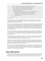
Rate-Limiting and Committed Access Rate
Rate-limiting controls the volume of data entering the network. It is generally deployed on routers
that aggregate customer links, and configured parameters may be used as the basis of charging
for the link.
In particular, if the capacity of the access circuit exceeds the network capacity required by the
customer, rate-limiting may restrict a customer's use of the network to the agreed level. Cisco
offers three traffic-shaping and policy tools: Generic Traffic Shaping, Frame Relay Traffic
Shaping, and CAR. This chapter focuses on the latter, CAR, because it is by far the most flexible
and powerful mechanism for IP environments.
CAR rate limits may be implemented either on input or output interfaces, and they work for
subinterface varieties, such as Frame Relay and ATM. They are usable only for IP traffic.
As shown in Figure 14-8, CAR performs three functions at the highest level. First, traffic is
passed through a filter. Second, packets matching the filter classification are passed through a
token bucket-based, traffic rate measurement system. Third, actions may be performed on the
packet, depending on the results of the traffic rate measurement system. These three functions
may be cascaded so that an individual packet may pass through a CAR policy consisting of
multiple match/measure/action stages.
Figure 14-8. CAR Performs Three Distinct Functions
Packets may be classified by physical port, source, destination IP or MAC address, application
port, IP protocol type, or other criteria specifiable by access lists or extended access lists.
Packets also may have been already classified by external sources, such as a customer or a
358
downstream network provider. This external classification may be accepted by the network, or
may be overridden and reclassified according to a specified policy. The CAR rate limit commands
set-prec-transmit and set-prec-continue are used for packet coloring and re-coloring.
Traffic rate measurement occurs via token bucket filters. Token bucket parameters include the
committed rate (in increments of 8 Kbps), the normal burst size, and the excess burst size.
Tokens are added to the bucket at the committed rate, and the number of tokens in the bucket is
limited by the normal burst size.
Arriving packets that find sufficient tokens available are said to conform. The appropriate number
of tokens is removed from the bucket, and the specified conform action is executed. Traffic
exceeding the normal burst limit, but falling within the excess burst limit, is handled via a RED-like
managed discard policy that provides a gradual effect for the rate limit and allows the traffic
sources to slow down before suffering sequential packet discards.
Some arriving packets might not conform to the token bucket specification, either because they
exceed the excess burst limit, or because they fall between the normal burst limit and the
maximum burst limit and were not probabilistically discarded. These packets are handled by the
specified exceed action.
Unlike a leaky bucket implementation, CAR does not smooth or shape the traffic; therefore, it
does not buffer or add delay.
You may configure the conform/exceed actions with the following information:
• Transmit
Switch the packet.
• Set precedence and transmit
Set the precedence bits in the Type of Service field in the IP packet header to a specified
value, and transmit. This action can be utilized to either color (set precedence) or recolor
(modify existing packet precedence) the packet.
• Drop
Discard the packet.
• Continue
Evaluate the next rate limit in a chain of rate limits.
• Set precedence and continue
Set the precedence bits to a specified value, and then evaluate the next rate limit in the
chain.
In case of VIP-based platforms, two more policies and one extra capability are possible:
• Set QoS group and transmit
359
The packet is assigned to a QoS group, and then is transmitted.
• Set QoS group and continue
The packet is assigned to a QoS group, and then is evaluated using the next rate policy.
If there is not another rate policy, the packet is transmitted.
• Cascading
This method enables a series of rate limits to be applied to packets. Cascading specifies
more granular policies to match packets against an ordered sequence of policies until an
applicable rate limit is reached, and the packet is either transmitted or discarded. Packets
that fall to the bottom of a list of rate limits are transmitted. You can configure up to 100
rate policies on a subinterface.
CAR can be used to partition network traffic into multiple priority levels or classes of service
(CoSs). You may define up to eight CoSs using the three precedence bits in the Type of Service
field in the IP header, and then utilize the other QoS features to assign appropriate traffic-
handling policies, including congestion management, bandwidth allocation, and delay bounds for
each traffic class. In particular, CAR may be used to apply this policy at the perimeter of the
network, leaving WRED to appropriately deal with packets within the core and distribution
networks.
The status of traffic shaping can be examined using the show traffic, show traffic statistics,
and show <interface> rate-limit commands.
BGP Policy Propagation
CAR and WRED provide QoS policy enforcement within the router, but how is this policy
propagated throughout the network? BGP policy propagation makes this possible by enabling you
to adjust the IP precedence of a packet based on its source or destination address and,
optionally, based on the associated BGP community and/or as-path. Recall from Chapter 11,
"Border Gateway Protocol," that an as-path is a mandatory BGP attribute that lists each
autonomous system through which the route has passed.
As shown in Figure 14-9, when a BGP best path (the most preferred BGP route to a destination)
is inserted into the CEF forwarding table, a table map may be applied via the table-map bgp
subcommand. The table map, which is actually a route map, matches the prefix based on IP
address, community, or as-path; and adds an IP precedence or QoS-group-id to the inserted CEF
entry. The IP precedence or QoS-group-id of any CEF entry can be viewed via the show ip cef
command.
Figure 14-9. When the Best BGP Route Is Inserted Into the CEF Forwarding Table, a Table
Map May Be Applied via the table-map bgp Subcommand
360
You can configure the IP precedence of a packet to be overwritten by the value in the CEF table
via the bgp-policy {source | destination} ip-prec-map interface subcommand. In addition, the
packet may be tagged with a QoS-group-id via the bgp-policy {source | destination} ip-qos-
map interface subcommand. Either the source or the destination address can be used for the
purpose of classifying the packet. After the precedence has been overwritten, or after a QoS tag
has been applied, CAR and WRED functionality can still be applied, as shown in Figure 14-9.
Note that the QoS-group-id is not part of the IP packet—it is stripped after the packet exits the
router—however, the modified IP precedence remains. Within the router, both the IP precedence
and the QoS-group-id can be used in conjunction with CAR functionality.
NOTE
In all cases, the associated interface must be configured for CEF or dCEF.
Both the table-map BGP subcommand and bgp-policy interface subcommand need to be
applied only where traffic classification and/or rate-limiting are required; routers deeper within the
network can differentiate between packets based on the overwritten IP Precedence field.
Note, however, that the router performing the classification must have the necessary BGP routing
information to perform the classification. This might mean that you need to carry extra routing
information in access routers if the classification is based on the destination address of the
packet. Figure 14-10 shows the reason for this.
Figure 14-10. Using BGP Policy Propagation: AS2 Is the Service Provider and AS1 and AS3
Are Customers
361
In Figure 14-10, AS2 is the service provider, and AS1 and AS3 are customers. If access router
A1 in AS2 receives traffic from AS1 that is destined for AS3, and classifies packets based on
BGP information associated with the source address, the route is successful because A1
receives BGP updates directly from AS1, containing the necessary classification data.
Consider, however, that AS3 wants all packets that it is destined to receive to be allocated a
certain IP precedence within AS2's network. This can occur only if router A1 receives BGP
updates about AS3's network. In short, the access-router in AS2 must carry routing information
about AS3, and any other AS for which QoS policy propagation is required. Access router A1
cannot use the default route for any destination networks requiring QoS policy.
In practice, this may not cause difficulty because any customer that expects QoS treatment will
probably want to receive a full set of routes from the provider anyway (for multihoming purposes,
for example). This means that A1 must carry full routes for all customers of AS2. Nevertheless,
this example demonstrates the increased requirements for access routers in terms of memory
and route computations, if BGP-QoS propagation and dual-homing is required.
Resource Reservation Protocol
RSVP is a soft-state signaling system that enables receivers to reserve resources for incoming
traffic flows. Flows are identified by destination address and the transport-layer protocol, and are,
therefore, unidirectional. The destination address can be a multicast group address; therefore,
from an RSVP perspective, unicast flows are simply a special case of multicast. More specifically,
in the unicast case, it is not necessary for a host to join a group prior to reserving resources via
RSVP.
Besides the queuing mechanisms of WRED and WFQ, RSVP also relies on the underlying
routing protocol to determine the path from sender to receiver. Although the receiver initiates
RSVP reservations, the protocol includes its own mechanisms for discovering the route, derived
362
from the routing protocol, from sender to receiver, and therefore does not rely on a symmetrically-
routed environment.
RSVP is a soft-state protocol, which means that the messages necessary for reserving resources
are periodically repeated. This process serves as a rudimentary protection against lost RSVP
messages, enables new participants to be added mid-session—such as when a new receiver or
sender joins a multicast group—and provides for changes in network routing.
Service Classes and Reservation Styles
NOTE
RSVP is simply a reservation scheme: it relies on the underlying interface queuing mechanisms
of WRED and WFQ to implement controlled load and guaranteed service reservations,
respectively.
Controlled load reservations tightly approximate the performance visible to best-effort applications
under unloaded conditions. That is, a high percentage of transmitted packets will be successfully
delivered, with a transit delay approximately equal to the router switching delays, in addition to
propagation and packetization delays.
NOTE
Switching delay is the amount of time the router needs to process and forward a packet;
propagation delay is the speed of light in the transmission media; and packetization delay is the
time required for a router to receive a packet on a particular link. For example, a 512-byte packet
on a 1 megabit/s link has a packetization delay of 512×8 bits/1,000,000 bits/s = 4 milliseconds.
In short, very little time is spent in packet queues. Applications requesting a controlled load
reservation indicate their performance requirements in the form of traffic specification (Tspec)
parameters carried in RSVP messages. If the traffic generated by the application exceeds these
requirements, the performance visible to the application will exhibit overload characteristics, such
as packet loss and large delays.
According to the RSVP standard, the overload conditions for RSVP-controlled load reservations
do not have to be equivalent to those of best-effort (non-QoS-reserved) traffic following the same
path through the network. They can be much better or much worse. WRED applies weights to
RSVP-controlled load flows appropriate to the Tspec parameters.
Guaranteed service reservations provide an assured level of bandwidth with delay-bounded
service. This delay bound refers to queuing delay only; switching, propagation, and packetization
delays must be added to the guaranteed service delay to determine the overall delay for packets.
WFQ weights are applied to provide the necessary queue-servicing to bound the queuing delay.
NOTE
The bandwidth available on any particular link on which RSVP/WFQ is enabled is allocated as
shown in Figure 14-11. Bandwidth is first allocated to reserved flows. This is followed by
bandwidth for interactive/low-volume, best-effort flows; and the remaining bandwidth is available
363
for high-bandwidth, best-effort flows. For RSVP/WRED, bandwidth is allocated first to reserved
flows, and then to best-effort flows.
Figure 14-11. Link Bandwidth Allocation with RSVP (a) and WRED (b)
RSVP supports three reservation styles, with more expected as the protocol evolves:
• A wildcard filter (WF) style reservationTraffic from all senders is grouped into a shared
pipe. The resources allocated to this shared pipe match the largest reservation by any
receiver using the pipe. This style is useful when there is usually only one or two active
senders from an entire group. An audio conference is a typical example. Each receiver
could request sufficient bandwidth to enable one or two senders (speakers) to speak at
the same time.
• A shared-explicit (SE) style reservationThis reservation method uses the same shared
pipe environment. However, the set of senders sharing the pipe is explicitly set by the
receiver making the reservation (no sender-wildcard). To use the audio-conference
example once more, with an SE style reservation, you still would reserve enough
resources to allow one or two people to speak—however, you are explicitly specifying
those people you want to hear. This style of reservation is obviously less convenient than
the WF style, but it provides greater control for the audience.
364
• A fixed filter (FF) styleThis method reserves resources for flows from an explicit list of
senders; the total reservation on any link is therefore the sum total of reservations for
each sender. When the destination is a multicast group of addresses, FF style
reservations from multiple receivers for the same sender must be merged, and the router
performing the multicast packet replication calculates the largest resource allocation.
Unicast reservations are generally fixed filter style, with a single sender specified.
RSVP uses IP protocol 46, although a UDP encapsulation using ports 1698 and 1699 is also
supported for hosts. The multicast address used by the router to send UDP-encapsulated
messages is set with the ip rsvp udp-multicast global configuration command.
RSVP Operation
The operation of RSVP is shown in Figure 14-12. Because the routed path from sender to
receiver may be asymmetric, such as when the path for traffic from Host A to Host B is via R1,
R2, R3, and the return path is via R3, R1, senders must prime the routers to expect reservation
requests for a particular flow. This is accomplished by using path messages from the sender to
the first hop router toward the receiver.
Figure 14-12. RSVP Operation
The first hop router inserts its own address as the path message's last hop, and forwards it to the
next hop router. This "last hop" field tells the next hop router where to forward a reservation
message for this particular flow.
This hop-by-hop processing of path messfages continues until the receiver is reached. At this
point, if the receiver sends a reservation message toward the sender, each router knows how to
forward the reservation message back to the sender so that it flows through each router in the
path from sender to receiver. The ip rsvp neighbor command can be used for neighboring
routers from which the local router will accept reservations.
If an error occurs in the processing of path or reservation messages, a path-error or reservation-
error message is generated and is routed hop-by-hop toward the sender or receiver, respectively.
Each error message includes objects sufficient to uniquely identify the path or reservation
message causing the error, and it always includes the ERROR-SPEC object. There are several
possible errors that can occur:
• Admission failureReservation could not be granted due to unavailable resources.
• Administrative rejectionPolicy forbids reservation.
• No Path information for Reservation message.
• No Sender information for Reservation message.
• Conflicting reservation styleThe style does not match the existing state.
• Unknown reservation style.
365
• Conflicting destination portsZero and non-zero destination port fields have appeared for
the same session.
• Conflicting sender portsZero and non-zero source port fields have appeared for the same
session.
• Service preemptedHard state already exists.
• Unknown object class.
• Unknown object type.
• Traffic Control ErrorMalformed requests have been issued.
• Traffic Control System Error.
• RSVP System ErrorImplementation-dependent debugging messages are present.
Paths and reservations have an associated refresh period, which is generally randomized within a
range to avoid congestion issues associated with synchronization of control messages. If this
period expires without a refresh of the reservation state, the reservation is expired. However, to
liberate resources in a more timely manner, a reservation TEARDOWN message is used to
remove the reservation even before its soft-state expires.
RSVP Protocol
Figure 14-13 shows the format of RSVP messages, which consist of a header containing seven
defined fields and one reserved field, followed by a main body containing a series of RSVP
objects.
Figure 14-13. RSVP Messages
Each message begins with a 4-bit RSVP version number: the current version is 2. This is followed
by a 4-bit flag field, which is currently unused. The type field indicates the message type:
Value Type
1 Path
2 Reservation-request
3 Path-error
366
4 Reservation-request error
5 Path-teardown
6 Reservation-teardown
7 Reservation-request acknowledgment
A 16-bit standard TCP/UDP checksum is used over the entire contents of the RSVP message.
The checksum field is assumed to be zero. Length is the RSVP packet length in bytes. The Send
TTL is matched to the TTL of the IP packet in which the RSVP message was encapsulated.
Each RSVP object field begins with an object length field, which must be one or more multiples of
4. The Class-Num and C-Type fields identify the object class and type, respectively. Currently
defined class/type combinations are shown in Table 14-1.
Table 14-1. RSVP Object Classes
Object Class
Description
Null Contains a Class-Num of 0, and its C-Type is ignored. Its length must be at
least 4, but can be any multiple of 4. A null object can appear anywhere in a
sequence of objects, and its contents will be ignored by the receiver.
Session Contains the IP destination address and possibly a generalized destination port
to define a specific session for the other objects that follow (required in every
RSVP message).
RSVP Hop Carries the IP address of the RSVP-capable node that sent this message.
Time Values If present, contains values for the refresh period and the state TTL to override
the default values.
Style Defines the reservation style, plus style-specific information that is not a flow-
specification or filter-specification object (included in the reservation-request
message).
Flow
Specification
Defines a desired QoS (included in a reservation-request message).
Filter
Specification
Defines a subset of session-data packets that should receive the desired QoS
(specified by a flow-specification object within a reservation-request message).
Sender
Template
Contains a sender IP address and perhaps some additional demultiplexing
information to identify a sender (included in a path message).
Sender TSPEC
Defines the traffic characteristics of a sender's data stream (included in the path
message).
Adspec Carries advertising data in a path message.
Error
Specification
Specifies an error (included in a path-error or reservation-request error
message).
Policy Data Carries information that will enable a local policy module to decide whether an
associated reservation is administratively permitted (included in a path or
reservation-request message).
Integrity
Contains cryptographic data to authenticate the originating node and perhaps to
verify the contents of this reservation-request message.
Scope An explicit specification of the scope for forwarding a reservation-request
message.
Reservation
Confirmation
Carries the IP address of a receiver that requested a confirmation. Can appear
in either a reservation-request or reservation-request acknowledgment.
367
RSVP is enabled on a (sub)interface basis using ip rsvp bandwidth [interface-kbps] [single-
flow-kbps]. By default, up to 75 percent of an interface bandwidth can be reserved by RSVP,
although this can be adjusted using the interface-kbps parameter; by default, single-flow-kbps
is 100 percent of the interface kbps.
Deploying QoS in Large Networks
As usual, the approach is to perform computational expensive functions at the perimeter of the
network, liberating the core and distribution networks to focus on aggregation and forwarding
functions. Hence, it is recommended that you deploy policy control functions on the network
perimeter and incorporate congestion avoidance, in the form of WRED, at the core. If traffic-
shaping and/or rate-limiting is required at the network perimeter, CAR represents the most
flexible solution.
This is not to say that congestion-management capabilities (such as priority or custom queuing)
will not find application in the network, but they should be used sparingly and with caution,
particularly on high-speed links.
In its current form, RSVP will be difficult to scale to a large network backbone. However, the
reservations can be mapped at the perimeter of the network into IP precedence.
If WRED is used in the core, the primary policy control that must be performed is the setting of IP
precedence. This can be achieved in three ways. First, the network operator may apply the
precedence based on policy (CAR access lists) configured into the IP precedence, either on the
host station or via routers in the customer network. Second, the network operator may apply
precedence in the access router to which the customer connects using static access lists. Third,
the customer may dynamically indicate to the network operator the IP precedence to associate
with each set of source addresses based on BGP communities. The case study at the end of the
chapter demonstrates the application of these ideas.
Summary
In this chapter, you examined various QoS solutions that are employed in building large networks.
In particular, you discovered the details of Cisco features that are available for congestion
management (FIFO, PQ, CQ, WFQ) and avoidance (WRED, CAR), as well as the means to
propagate QoS policy through the network (IP precedence, BGP policy propagation, and RSVP).
Although the various fancy queuing mechanisms and soft-state mechanisms such as RSVP are
highly flexible solutions, they consume valuable resources, and current implementations are
applicable only to line rates in the low megabits per second. However, the combination of CAR on
the perimeter, WRED in the core for congestion avoidance, and BGP for intra/interdomain QoS
signaling represents a highly-scalable and easily-managed suite of features for the deployment of
differentiated services on a large scale.
Implementation of differentiated services within a network is a highly contentious issue. Clearly,
the mechanisms described in this chapter are not a solution for a poorly-scaled or under-
engineered network. However, mechanisms such as WFQ and WRED can improve the perceived
quality and utilization of network bandwidth.
368
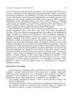
Case Study: Applying Differentiated Service in a Large
Network
This case study describes the QoS architecture of a large service
provider network. We use the network topology developed in Chapter
4, "Network Topologies," as a model for this case study. Figure 14-
14 shows the QoS architecture for this topology. In summary, WRED is
deployed on all backbone links; WRED or WFQ is deployed on links to
customers, possibly in addition to CAR.
Configuring the distribution and core routes is trivial: simply enable
WRED via the random-detect command on all interfaces where output
congestion is expected. DWRED should be used where possible. As a
general rule, the default WRED parameter settings are appropriate.
If the customer is left to set the IP precedence of incoming packets,
access router QoS configuration can be as simple as enabling WRED on
the interface leading to the service provider. However, one should
consider the issues involved in allowing the customer to assign IP policy
for their traffic. There must be a level of expertise with the customer
network that will permit them to make appropriate IP precedence
configurations within their own hosts or routers. Perhaps more
importantly, there must be some restrictions to prevent customers from
using the critical preference values reserved for network administrative
functions, such as routing.
The last point is the need to police incoming precedence levels upon
ingress to the network, similar to the way in which routing updates or
packet source addresses are handled. This encourages the provider to
implement QoS policy, regardless of customer actions. Policing can be
achieved via CAR or via the ip policy-map interface subcommand and
an associated route map.
The access router can be configured to apply policy based on access
lists. At the same time, various CAR rate-limit policies can be applied.
This approach is static: the customers are not allowed the flexibility of
adjusting the level of service that they wish to have applied to various
traffic sources.
If the customers offer routes to the provider via BGP, this can be used to
set the appropriate precedence level upon ingress to the network via
BGP policy propagation. This allows the IP precedence associated with
the each prefix to be dynamically signaled to the network.
Customer-initiated QoS policy changes are sent to the provider by
369
updating, for example, the community assigned to a prefix, and then
sending a new BGP update to the provider. Moreover, the provider can
propagate this information to other customers, as well as other network
operators, allowing them to implement their own policies.
Figure 14-14. QoS Architecture for a Large Network
Review Questions
1:
Many switching modes can be employed. How can you determine which mode is
enabled on a particular interface?
2:
Is over-engineering network bandwidth cheaper than deploying various
complicated QoS strategies?
3:
Should you use CAR, WRED, WFQ, or RSVP?
4:
Should you manage congestion, or avoid it altogether?
5:
An example network has multiprotocol traffic such as AppleTalk, IPX, and SNA
traffic. Can you still use WRED in this environment?