ccna study guide by sybex phần 8 docx
Bạn đang xem bản rút gọn của tài liệu. Xem và tải ngay bản đầy đủ của tài liệu tại đây (5.86 MB, 75 trang )
Frame Relay 491
7. The CO receives the frame and sends it through the Frame Relay
“cloud” to its destination. This cloud can be dozens of switching
offices—or more! It looks for the destination IP address and DLCI
number. It typically can find the DLCI number of the remote device or
router by looking up an IP-to-DLCI mapping. Frame Relay mappings
are usually created statically by the service provider, but they can be
created dynamically using the Inverse ARP (IARP) protocol. Remem-
ber that before data is sent through the cloud, the virtual circuit is cre-
ated from end to end.
8. Once the frame reaches the switching office closest to the destination
office, it is sent through the local loop. The frame is received at the
demarc and then is sent to the CSU/DSU. Finally, the router extracts
the packet, or datagram, from the frame and puts the packet in a
new LAN frame to be delivered to the destination host. The frame on
the LAN will have the final destination hardware address in the
header. This was found in the router’s ARP cache, or an ARP broad-
cast was performed. Whew!
The user and server do not need to know, nor should they know, every-
thing that happens as the frame makes its way across the Frame Relay net-
work. The remote server should be as easy to use as a locally connected
resource.
Frame Relay Encapsulation
When configuring Frame Relay on Cisco routers, you need to specify it as an
encapsulation on serial interfaces. There are only two encapsulation types:
Cisco and IETF (Internet Engineering Task Force). The following router
output shows the two different encapsulation methods when choosing
Frame Relay on your Cisco router:
RouterA(config)#int s0
RouterA(config-if)#encapsulation frame-relay ?
ietf Use RFC1490 encapsulation
<cr>
The default encapsulation is Cisco unless you manually type in IETF, and
Cisco is the type used when connecting two Cisco devices. You’d opt for
the IETF-type encapsulation if you needed to connect a Cisco device to a
Copyright ©2000 SYBEX , Inc., Alameda, CA
www.sybex.com
492 Chapter 10
Wide Area Networking Protocols
non-Cisco device with Frame Relay. So before choosing an encapsulation
type, check with your ISP and find out which one they use. (If they don’t
know, hook up with a different ISP!)
Data Link Connection Identifiers (DLCIs)
Frame Relay virtual circuits (PVCs) are identified by DLCIs. A Frame Relay
service provider, such as the telephone company, typically assigns DLCI val-
ues, which are used by Frame Relay to distinguish between different virtual cir-
cuits on the network. Because many virtual circuits can be terminated on one
multipoint Frame Relay interface, many DLCIs are often affiliated with it.
For the IP devices at each end of a virtual circuit to communicate, their IP
addresses need to be mapped to DLCIs. This mapping can function as a mul-
tipoint device—one that can identify to the Frame Relay network the appro-
priate destination virtual circuit for each packet that is sent over the single
physical interface. The mappings can be done dynamically through IARP or
manually through the Frame Relay map command.
Frame Relay uses DLCIs the same way that X.25 uses X.121 addresses,
and every DLCI number can be given either global or local meaning every-
where within the Frame Relay network.
Sometimes a provider can give a site a DLCI that is advertised to all
remote sites as the same PVC. This PVC is said to have a global significance.
For example, a corporate office might have a DLCI of 20. All remote sites
would know that the corporate office is DLCI 20 and use this PVC to com-
municate to the corporate office. However, the customary implementation is
to give each DLCI local meaning. What does this mean? It means that DLCI
numbers do not necessarily need to be unique. Two DLCI numbers can be
the same on different sides of a link because Frame Relay maps a local DLCI
number to a virtual circuit on each interface of the switch. Each remote office
can have its own DLCI number and communicate with the corporate office
using unique DLCI numbers.
DLCI numbers, used to identify a PVC, are typically assigned by the pro-
vider and start at 16. Configuring a DLCI number to be applied to an inter-
face is shown below:
RouterA(config-if)#frame-relay interface-dlci ?
<16-1007> Define a DLCI as part of the current
subinterface
RouterA(config-if)#frame-relay interface-dlci 16
Copyright ©2000 SYBEX , Inc., Alameda, CA
www.sybex.com
Frame Relay 493
Local Management Interface (LMI)
The Local Management Interface (LMI) was developed in 1990 by Cisco
Systems, StrataCom, Northern Telecom, and Digital Equipment Corpora-
tion and became known as the Gang-of-Four LMI or Cisco LMI. This gang
took the basic Frame Relay protocol from the CCIT and added extensions
onto the protocol features that allow internetworking devices to communi-
cate easily with a Frame Relay network.
The LMI is a signaling standard between a CPE device (router) and a frame
switch. The LMI is responsible for managing and maintaining status between
these devices. LMI messages provide information about the following:
Keepalives Verify data is flowing
Multicasting Provides a local DLCI PVC
Multicast addressing Provides global significance
Status of virtual circuits Provides DLCI status
Beginning with IOS version 11.2, the LMI type is auto-sensed. This enables the
interface to determine the LMI type supported by the switch.
If you’re not going to use the auto-sense feature, you’ll need to check with
your Frame Relay provider to find out which type to use instead. The default
type is Cisco, but you may need to change to ANSI or Q.933A. The three dif-
ferent LMI types are depicted in the router output below.
RouterA(config-if)#frame-relay lmi-type ?
cisco
ansi
q933a
As seen in the output, all three standard LMI signaling formats are
supported:
Cisco LMI defined by the Gang of Four (default)
ANSI Annex D defined by ANSI standard T1.617
ITU-T (q933a) Annex A defined by Q.933
Copyright ©2000 SYBEX , Inc., Alameda, CA
www.sybex.com
494 Chapter 10
Wide Area Networking Protocols
Routers receive LMI information on a frame-encapsulated interface and
update the virtual circuit status to one of three different states:
Active state Everything is up and routers can exchange information.
Inactive state The router’s interface is up and working with a connec-
tion to the switching office, but the remote router is not working.
Deleted state This means that no LMI information is being received
on the interface from the switch. It could be a mapping problem or a line
failure.
Subinterfaces
You can have multiple virtual circuits on a single serial interface and yet treat
each as a separate interface. These are known as subinterfaces. Think of a
subinterface as a hardware interface defined by the IOS software. An advan-
tage gained through using subinterfaces is the ability to assign different Net-
work layer characteristics to each subinterface and virtual circuit, such as IP
routing on one virtual circuit and IPX on another.
Partial Meshed Networks
You can use subinterfaces to mitigate partial meshed Frame Relay networks
and split horizon protocols. For example, say you were running the IP pro-
tocol on a LAN network. If, on the same physical network, Router A can talk
to Router B, and Router B to Router C, you can usually assume that Router
A can talk to Router C. Though this is true with a LAN, it’s not true with a
Frame Relay network, unless Router A has a PVC to Router C.
In Figure 10.5, Network 1 is configured with five locations. To be able to
make this network function, you would have to create a meshed network as
shown in Network 2. However, even though Network 2’s example works,
it’s an expensive solution—configuring subinterfaces as shown in the Net-
work 3 solution is much more cost-effective.
In Network 3, configuring subinterfaces actually works to subdivide the
Frame Relay network into smaller subnetworks—each with its own network
number. So locations A, B, and C connect to a fully meshed network, while
locations C and D, and D and E, are connected via point-to-point connec-
tions. Locations C and D connect to two subinterfaces and forward packets.
Subinterfaces also solve the problem with routing protocols that use split
horizon. As you may recall, split horizon protocols do not advertise routes
Copyright ©2000 SYBEX , Inc., Alameda, CA
www.sybex.com
Frame Relay 495
out the same interface they received the route update on. This can cause a
problem on a meshed Frame Relay network. However, by using subinter-
faces, routing protocols that receive route updates on one subinterface can
send out the same route update on another subinterface.
FIGURE 10.5 Partial meshed network examples
Creating Subinterfaces
You define subinterfaces with the int s0.subinterface number com-
mand as shown below. You first set the encapsulation on the serial interface,
then you can define the subinterfaces.
RouterA(config)#int s0
RouterA(config)#encapsulation frame-relay
Copyright ©2000 SYBEX , Inc., Alameda, CA
www.sybex.com
496 Chapter 10
Wide Area Networking Protocols
RouterA(config)#int s0.?
<0-4294967295> Serial interface number
RouterA(config)#int s0.16 ?
multipoint Treat as a multipoint link
point-to-point Treat as a point-to-point link
You can define an almost limitless number of subinterfaces on a given
physical interface (keeping router memory in mind). In the above example,
we chose to use subinterface 16 because that represents the DLCI number
assigned to that interface. However, you can choose any number between 0
and 4,292,967,295.
There are two types of subinterfaces:
Point-to-point Used when a single virtual circuit connects one router to
another. Each point-to-point subinterface requires its own subnet.
Multipoint Used when the router is the center of a star of virtual cir-
cuits. Uses a single subnet for all routers’ serial interfaces connected to the
frame switch.
An example of a production router running multiple subinterfaces is
shown below. Notice that the subinterface number matches the DLCI num-
ber. This is not a requirement but helps in the administration of the inter-
faces. Also notice that there is no LMI type defined, which means they are
running either the default of Cisco or using autodetect if running Cisco IOS
version 11.2 or newer. This configuration was taken from one of my cus-
tomers’ production routers (used by permission). Notice that each interface
is defined as a separate subnet, separate IPX network, and separate Apple-
Talk cable range (AppleTalk is beyond the scope of this course):
interface Serial0
no ip address
no ip directed-broadcast
encapsulation frame-relay
!
interface Serial0.102 point-to-point
ip address 10.1.12.1 255.255.255.0
no ip directed-broadcast
appletalk cable-range 12-12 12.65
appletalk zone wan2
Copyright ©2000 SYBEX , Inc., Alameda, CA
www.sybex.com
Frame Relay 497
appletalk protocol eigrp
no appletalk protocol rtmp
ipx network 12
frame-relay interface-dlci 102
!
interface Serial0.103 point-to-point
ip address 10.1.13.1 255.255.255.0
no ip directed-broadcast
appletalk cable-range 13-13 13.174
appletalk zone wan3
appletalk protocol eigrp
no appletalk protocol rtmp
ipx network 13
frame-relay interface-dlci 103
!
interface Serial0.104 point-to-point
ip address 10.1.14.1 255.255.255.0
no ip directed-broadcast
appletalk cable-range 14-14 14.131
appletalk zone wan4
appletalk protocol eigrp
no appletalk protocol rtmp
ipx network 14
frame-relay interface-dlci 104
!
interface Serial0.105 point-to-point
ip address 10.1.15.1 255.255.255.0
no ip directed-broadcast
appletalk cable-range 15-15 15.184
appletalk zone wan5
appletalk protocol eigrp
no appletalk protocol rtmp
ipx network 15
frame-relay interface-dlci 105
!
interface Serial0.106 point-to-point
Copyright ©2000 SYBEX , Inc., Alameda, CA
www.sybex.com
498 Chapter 10
Wide Area Networking Protocols
ip address 10.1.16.1 255.255.255.0
no ip directed-broadcast
appletalk cable-range 16-16 16.28
appletalk zone wan6
appletalk protocol eigrp
no appletalk protocol rtmp
ipx network 16
frame-relay interface-dlci 106
!
interface Serial0.107 point-to-point
ip address 10.1.17.1 255.255.255.0
no ip directed-broadcast
appletalk cable-range 17-17 17.223
appletalk zone wan7
appletalk protocol eigrp
no appletalk protocol rtmp
ipx network 17
frame-relay interface-dlci 107
!
interface Serial0.108 point-to-point
ip address 10.1.18.1 255.255.255.0
no ip directed-broadcast
appletalk cable-range 18-18 18.43
appletalk zone wan8
appletalk protocol eigrp
no appletalk protocol rtmp
ipx network 18
frame-relay interface-dlci 108
Mapping Frame Relay
As we explained earlier, in order for IP devices at the ends of virtual circuits
to communicate, their addresses must be mapped to the DLCIs. There are
two ways to make this mapping happen:
Use the Frame Relay map command.
Use the inverse-arp function.
Copyright ©2000 SYBEX , Inc., Alameda, CA
www.sybex.com
Frame Relay 499
Here’s an example using the Frame Relay map command:
RouterA(config)#int s0
RouterA(config-if)#encap frame
RouterA(config-if)#int s0.16 point-to-point
RouterA(config-if)#no inverse-arp
RouterA(config-if)#ip address 172.16.30.1 255.255.255.0
RouterA(config-if)#frame-relay map ip 172.16.30.17 16 ietf
broadcast
RouterA(config-if)#frame-relay map ip 172.16.30.18 17
broadcast
RouterA(config-if)#frame-relay map ip 172.16.30.19 18
Here’s what we did: First, we chose configured interface serial 0 to use the
encapsulation type of Cisco (default), then we created our subinterface. We
then turned off inverse arp and mapped three virtual circuits and their cor-
responding DLCI numbers.
Notice that we changed the encapsulation type for the first mapping. The
frame map command is the only way to configure multiple frame encapsu-
lation types on an interface.
The broadcast keyword at the end of the map command tells the router
to forward broadcasts for this interface to this specific virtual circuit.
Remember that Frame Relay is a nonbroadcast multiaccess (NBMA) encap-
sulation method, which will not broadcast routing protocols. You can either
use the map command with the broadcast keyword or the neighbor com-
mand within the routing process.
Instead of putting in map commands for each virtual circuit, you can use
the inverse-arp function to perform dynamic mapping of the IP address
to the DLCI number. This makes our configuration look like this:
RouterA(config)#int s0.16 point-to-point
RouterA(config-if)#encap frame-relay ietf
RouterA(config-if)#ip address 172.16.30.1 255.255.255.0
Yes, this configuration is a whole lot easier to do, but it’s not as stable as
using the map command. Why? Sometimes, when using the inverse-arp
function, configuration errors occur because virtual circuits can be insidi-
ously and dynamically mapped to unknown devices.
Copyright ©2000 SYBEX , Inc., Alameda, CA
www.sybex.com
500 Chapter 10
Wide Area Networking Protocols
Frame Relay Congestion Control
In this section we will define how the Frame Relay switch handles congestion
problems.
DE (Discard Eligibility) When a Frame Relay router detects congestion
on the Frame Relay network, it will turn the DE bit on in a Frame Relay
packet header. If the switch is congested, the Frame Relay switch will dis-
card the packets with the DE bit set first. If your bandwidth is configured
with a CIR of zero, the DE will always be on.
FECN (Forward-Explicit Congestion Notification) When the Frame
Relay network recognizes congestion in the cloud, the switch will set the
FECN bit to 1 in a Frame Relay packet header. This will indicate to the
destination DCE that the path just traversed is congested.
BECN (Backward-Explicit Congestion Notification) When the switch
detects congestion in the Frame Relay network, it will set the BECN bit in
a Frame Relay packet and send it to the source router, telling it to slow
down the rate at which it is transmitting packets.
Committed Information Rate (CIR)
Frame Relay provides a packet-switched network to many different custom-
ers at the same time. This is a great idea because it spreads the cost of the
switches among many customers. However, Frame Relay is based on the
assumption that not all customers need to transmit constant data all at the
same time. Frame Relay works best with bursty traffic.
Think of Frame Relay as a party line. Remember party lines? That is when
many people on your block had to share the same phone number. Okay, I am
showing my age here, but understand that party lines were created on the
assumption that few people needed to use the phone each day. If you needed
to talk excessively, you had to pay for the more expensive dedicated circuit.
Frame Relay works somewhat on the same principle, except many devices
can transmit at the same time. However, if you need a constant data-stream
connection, then Frame Relay is not for you. Buy a dedicated, point-to-point
T-1 instead.
Frame Relay works by providing a dedicated bandwidth to each user,
who is committed to that bandwidth at any given time. Frame Relay provid-
ers allow customers to buy a lower amount of bandwidth than what they
Copyright ©2000 SYBEX , Inc., Alameda, CA
www.sybex.com
Frame Relay 501
really might need. This is called the Committed Information Rate (CIR).
What this means is that the customer can buy bandwidth of, for example,
256k, but it is possible to burst up to T-1 speeds. The CIR specifies that as
long as the data input by a device to the Frame Relay network is below or
equal to the CIR, then the network will continue to forward data for the
PVC. However, if data rates exceed the CIR, it is not guaranteed.
It is sometimes possible to also purchase a Bc (Committed Burst), which
allows customers to exceed their CIR for a specified amount of time. In this
situation, the DE bit will always be set.
Choose a CIR based on realistic, anticipated traffic rates. Some Frame
Relay providers allow you to purchase a CIR of zero. You can use a zero CIR
to save money if retransmission of packets is acceptable. However, under-
stand that the DE bit will always be turned on in every frame.
Monitoring Frame Relay
There are several ways to check the status of your interfaces and PVCs once
you have Frame Relay encapsulation set up and running:
RouterA>sho frame ?
ip show frame relay IP statistics
lmi show frame relay lmi statistics
map Frame-Relay map table
pvc show frame relay pvc statistics
route show frame relay route
traffic Frame-Relay protocol statistics
Show Frame-Relay Lmi
The show frame-relay lmi command will give you the LMI traffic statis-
tics exchanged between the local router and the Frame Relay switch.
Router#sh frame lmi
LMI Statistics for interface Serial0 (Frame Relay DTE) LMI TYPE
= CISCO
Invalid Unnumbered info 0 Invalid Prot Disc 0
Invalid dummy Call Ref 0 Invalid Msg Type 0
Invalid Status Message 0 Invalid Lock Shift 0
Copyright ©2000 SYBEX , Inc., Alameda, CA
www.sybex.com
502 Chapter 10
Wide Area Networking Protocols
Invalid Information ID 0 Invalid Report IE Len 0
Invalid Report Request 0 Invalid Keep IE Len 0
Num Status Enq. Sent 0 Num Status msgs Rcvd 0
Num Update Status Rcvd 0 Num Status Timeouts 0
Router#
The router output from the show frame-relay lmi command shows you
LMI errors as well as the LMI type.
Show Frame-Relay Pvc
The show frame pvc command will list all configured PVCs and DLCI num-
bers. It provides the status of each PVC connection and traffic statistics. It
will also give you the number of BECN and FECN packets received on the
router.
RouterA#sho frame pvc
PVC Statistics for interface Serial0 (Frame Relay DTE)
DLCI = 16,DLCI USAGE = LOCAL,PVC STATUS =ACTIVE,INTERFACE
= Serial0.1
input pkts 50977876 output pkts 41822892 in bytes
3137403144
out bytes 3408047602 dropped pkts 5 in FECN pkts 0
in BECN pkts 0 out FECN pkts 0 out BECN pkts 0
in DE pkts 9393 out DE pkts 0
pvc create time 7w3d, last time pvc status changed 7w3d
DLCI = 18,DLCI USAGE =LOCAL,PVC STATUS =ACTIVE,INTERFACE =
Serial0.3
input pkts 30572401 output pkts 31139837 in bytes
1797291100
out bytes 3227181474 dropped pkts 5 in FECN pkts 0
in BECN pkts 0 out FECN pkts 0 out BECN pkts 0
in DE pkts 28 out DE pkts 0
pvc create time 7w3d, last time pvc status changed 7w3d
Copyright ©2000 SYBEX , Inc., Alameda, CA
www.sybex.com
Frame Relay 503
To see information about only PVC 16, you can type the command show
frame-relay pvc 16.
Show Interface
We can also use the show interface command to check for LMI traffic.
The show interface command displays information about the encapsula-
tion as well as layer-2 and layer-3 information.
The LMI DLCI, as bolded in the command, is used to define the type of
LMI being used. If it is 1023, it is the default LMI type of Cisco. If the LMI
DLCI is zero, then it is the ANSI LMI type.
RouterA#sho int s0
Serial0 is up, line protocol is up
Hardware is HD64570
MTU 1500 bytes, BW 1544 Kbit, DLY 20000 usec, rely 255/
255, load 2/255
Encapsulation FRAME-RELAY, loopback not set, keepalive
set (10 sec)
LMI enq sent 451751,LMI stat recvd 451750,LMI upd recvd
164,DTE LMI up
LMI enq recvd 0, LMI stat sent 0, LMI upd sent 0
LMI DLCI 1023 LMI type is CISCO frame relay DTE
Broadcast queue 0/64, broadcasts sent/dropped 0/0,
interface broadcasts 839294
The show interface command displays line, protocol, DLCI, and LMI
information.
Show Frame Map
The show frame map command will show you the Network layer–to–DLCI
mappings.
RouterB#show frame map
Serial0 (up): ipx 20.0007.7842.3575 dlci 16(0x10,0x400),
dynamic, broadcast,, status defined, active
Serial0 (up): ip 172.16.20.1 dlci 16(0x10,0x400),
dynamic,
broadcast,, status defined, active
Copyright ©2000 SYBEX , Inc., Alameda, CA
www.sybex.com
504 Chapter 10
Wide Area Networking Protocols
Serial1 (up): ipx 40.0007.7842.153a dlci 17(0x11,0x410),
dynamic, broadcast,, status defined, active
Serial1 (up): ip 172.16.40.2 dlci 17(0x11,0x410),
dynamic,
broadcast,, status defined, active
Notice that the search interface has two mappings, one for IP and one for
IPX. Also, notice that the Network layer addresses were resolved with the
dynamic protocol Inverse ARP (IARP). If an administrator mapped the
addresses, the output would say “static.”
After the DLCI number is listed, you can see some numbers in parenthe-
ses. Notice the first number is 0x10, which is the hex equivalent for the DLCI
number 16 used on serial 0, and the 0x11 is the hex for DLCI 17 used on
serial 1. The second numbers, 0x400 and 0x410, are the DLCI numbers con-
figured in the Frame Relay frame. They are different because of the way the
bits are spread out in the frame.
To clear the dynamic mappings, you can use the command clear frame-
relay-inarp.
Debug Frame Lmi
The debug frame lmi command will show output on the router consoles by
default. The information from this command will allow you to verify and
troubleshoot the Frame Relay connection by helping you to determine
whether the router and switch are exchanging the correct LMI information.
Router#debug frame-relay lmi
Serial3/1(in): Status, myseq 214
RT IE 1, length 1, type 0
KA IE 3, length 2, yourseq 214, myseq 214
PVC IE 0x7 , length 0x6 , dlci 130, status 0x2 , bw 0
Serial3/1(out): StEnq, myseq 215, yourseen 214, DTE up
datagramstart = 0x1959DF4, datagramsize = 13
FR encap = 0xFCF10309
00 75 01 01 01 03 02 D7 D6
Copyright ©2000 SYBEX , Inc., Alameda, CA
www.sybex.com
Integrated Services Digital Network (ISDN) 505
Serial3/1(in): Status, myseq 215
RT IE 1, length 1, type 1
KA IE 3, length 2, yourseq 215, myseq 215
Serial3/1(out): StEnq, myseq 216, yourseen 215, DTE up
datagramstart = 0x1959DF4, datagramsize = 13
FR encap = 0xFCF10309
00 75 01 01 01 03 02 D8 D7
Integrated Services Digital Network (ISDN)
Integrated Services Digital Network (ISDN) is a digital service designed
to run over existing telephone networks. ISDN can support both data and
voice—a telecommuter’s dream. But ISDN applications require bandwidth.
Typical ISDN applications and implementations include high-speed image
applications (such as Group IV facsimile), high-speed file transfer, videocon-
ferencing, and multiple links into homes of telecommuters.
ISDN is actually a set of communication protocols proposed by tele-
phone companies that allows them to carry a group of digital services that
simultaneously convey data, text, voice, music, graphics, and video to end
users, and it was designed to achieve this over the telephone systems
already in place. ISDN is referenced by a suite of ITU-T standards that
encompass the OSI model’s Physical, Data Link, and Network layers. The
ISDN standards define the hardware and call-setup schemes for end-to-end
digital connectivity.
PPP is typically used with ISDN to provide data encapsulation, link integ-
rity, and authentication. These are the benefits of ISDN:
Can carry voice, video, and data simultaneously
Has faster call setup than a modem
Has faster data rates than a modem connection
Copyright ©2000 SYBEX , Inc., Alameda, CA
www.sybex.com
506 Chapter 10
Wide Area Networking Protocols
ISDN Components
The components used with ISDN include functions and reference points. Fig-
ure 10.6 shows how the different types of terminal and reference points can
be used in an ISDN network.
FIGURE 10.6 ISDN functions and reference points
In North America, ISDN uses a two-wire connection into a home or
office. That is called a “U” reference point. The NT1 device is used to con-
vert the two-wire connection to a four-wire connection that is used by ISDN
phones and terminal adapters (TAs). Most routers can now be purchased
with a built-in NT1 (U) interface.
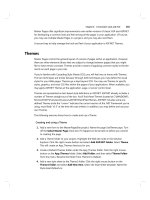
Figure 10.7 shows the different reference points and terminal equipment
that can be used with Cisco ISDN BRI interfaces.
R
S/T
U
S/T
U
U
TA NT1
NT1
ISDN switch
service
Router with
built-in NT1
ISDN
device (TE1)
Non-ISDN
device (TE2)
Copyright ©2000 SYBEX , Inc., Alameda, CA
www.sybex.com
Integrated Services Digital Network (ISDN) 507
FIGURE 10.7 ISDN BRI reference points and terminal equipment
ISDN Terminals
Devices connecting to the ISDN network are known as terminal equipment
(TE) and network termination (NT) equipment. There are two types of each:
TE1 Terminal equipment type 1 refers to those terminals that under-
stand ISDN standards and can plug right into an ISDN network.
TE2 Terminal equipment type 2 refers to those that predate ISDN stan-
dards. To use a TE2, you have to use a terminal adapter (TA) to be able
to plug into an ISDN network.
NT1 Network termination 1 implements the ISDN Physical layer spec-
ifications and connects the user devices to the ISDN network.
NT2 Network termination 2 is typically a provider’s equipment, such as
a switch or PBX. It also provides Data Link and Network layer implemen-
tation. It’s very rare at a customer premises.
TA Terminal adapter converts TE2 wiring to TE1 wiring that then con-
nects into an NT1 device for conversion into a two-wire ISDN network.
S/T
S/T
R
S0
U
bri0
bri0
Native ISDN interface—int bri0
Nonnative ISDN interface—int serial 0
(EIA/TIA-232, V.35, X.21)
Service provider
network
TE1
NT1
NT1NT1
TE1
NT1
TE2
Copyright ©2000 SYBEX , Inc., Alameda, CA
www.sybex.com
508 Chapter 10
Wide Area Networking Protocols
ISDN Reference Points
Reference points are a series of specifications that define the connection
between the various equipment used in an ISDN network. ISDN has four ref-
erence points that define logical interfaces:
R reference point Defines the reference point between non-ISDN equip-
ment (TE2) and a TA.
S reference point Defines the reference point between the customer
router and an NT2. Enables calls between the different customer equip-
ment.
T reference point Defines the reference point between NT1 and NT2
devices. S and T reference points are electrically the same and can perform
the same function. Therefore, they are sometimes referred to as an S/T ref-
erence point.
U reference point Defines the reference point between NT1 devices and
line-termination equipment in a carrier network. (This is only in North
America where the NT1 function isn’t provided by the carrier network.)
ISDN Protocols
ISDN protocols are defined by the ITU, and there are several series of pro-
tocols dealing with diverse issues:
Protocols beginning with the letter E deal with using ISDN on the
existing telephone network.
Protocols beginning with the letter I deal with concepts, aspects, and
services.
Protocols beginning with the letter Q cover switching and signaling.
ISDN Switch Types
We can credit AT&T and Nortel for the majority of the ISDN switches in
place today, but additional companies also make them. In Table 10.1 under
“Keyword,” you’ll find the right keyword to use along with the isdn
switch-type command to configure a router for the variety of switches it’s
Copyright ©2000 SYBEX , Inc., Alameda, CA
www.sybex.com
Integrated Services Digital Network (ISDN) 509
going to connect to. If you don’t know which switch your provider is using
at their central office, simply call them to find out.
Basic Rate Interface (BRI)
ISDN Basic Rate Interface (BRI, also known as 2B+1D) service provides two
B channels and one D channel. The BRI B-channel service operates at
64Kbps and carries data, while the BRI D-channel service operates at
16Kbps and usually carries control and signaling information.
The D-channel signaling protocol spans the OSI reference model’s Physi-
cal, Data Link, and Network layers. The D channel carries signaling infor-
mation to set up and control calls. The D channel can also be used for other
functions like an alarm system for a building, or anything that doesn’t need
much bandwidth, since it is only a whopping 16k. D channels work with
LAPD at the Data Link layer.
When configuring ISDN BRI, you will need to obtain SPIDs (Service Pro-
file Identifiers), and you should have one SPID for each B channel. SPIDs can
be thought of as the telephone number of each B channel. The ISDN device
gives the SPID to the ISDN switch, which then allows the device to access the
network for BRI or PRI service. Without a SPID, many ISDN switches don’t
allow an ISDN device to place a call on the network.
To set up a BRI call, four events must take place:
1. The D channel between the router and the local ISDN switch comes up.
TABLE 10.1 ISDN Switch Types
Switch Type Keyword
AT&T basic rate switch Basic-5ess
Nortel DMS-100 basic rate switch Basic-dms100
National ISDN-1 switch Basic-ni1
AT&T 4ESS (ISDN PRI only) Primary-4ess
AT&T 5ESS (ISDN PRI only) Primary-5ess
Nortel DMS-100 (ISDN PRI only) Primary-dms100
Copyright ©2000 SYBEX , Inc., Alameda, CA
www.sybex.com
510 Chapter 10
Wide Area Networking Protocols
2. The ISDN switch uses the SS7 signaling technique to set up a path to
a remote switch.
3. The remote switch sets up the D-channel link to the remote router.
4. The B channels are then connected end-to-end.
Primary Rate Interface (PRI)
In North America and Japan, the ISDN Primary Rate Interface (PRI, also
known as 23B+D1) service delivers 23 64Kbps B channels and one 64Kbps
D channel for a total bit rate of up to 1.544Mbps.
In Europe, Australia, and other parts of the world, ISDN provides 30
64Kbps B channels and one 64Kbps D channel for a total bit rate of up to
2.048Mbps.
ISDN with Cisco Routers
Accessing ISDN with a Cisco router means that you will need to purchase
either a router with a built-in NT1 (U reference point) or an ISDN modem
(called a TA). If your router has a BRI interface, you’re ready to rock. Oth-
erwise, you can use one of your router’s serial interfaces if you can get ahold
of a TA. A router with a BRI interface is called a TE1 (terminal endpoint 1),
and one that requires a TA is called a TE2 (terminal endpoint 2).
ISDN supports virtually every upper-layer network protocol (IP, IPX,
AppleTalk, you name it), and you can choose PPP, HDLC, or LAPD as your
encapsulation protocol.
When configuring ISDN, you’ll need to know the type of switch that your ser-
vice provider is using. To see which switches your router will support, use the
isdn switch-type ? command in global configuration mode or interface con-
figuration mode. You need to do this because each manufacturer has a pro-
prietary protocol for signaling.
For each ISDN BRI interface, you need to specify the SPIDs that are using
the isdn spid1 and isdn spid2 interface subcommands. These are pro-
vided by the ISDN provider and identify you on the switch, sort of like a tele-
phone number. However, some providers no longer require SPIDs to be
configured on the router. Check with your provider to be sure.
Copyright ©2000 SYBEX , Inc., Alameda, CA
www.sybex.com
Dial-on-Demand Routing (DDR) 511
The second part of the SPID configuration is the local dial number for that
SPID. It is optional, but some switches need to have those set on the router
in order to use both B channels simultaneously.
An example is shown below:
RouterA#config t
Enter configuration commands, one per line. End with CNTL/Z.
RouterA(config)#isdn switch-type basic-ne1
RouterA(config)#int bri0
RouterA(config-if)#encap ppp (optional)
RouterA(config-if)#isdn spid1 086506610100 8650661
RouterA(config-if)#isdn spid2 086506620100 8650662
The isdn switch-type command can be configured in either global configu-
ration or interface configuration mode. Configuring the switch type global will
set the switch type for all BRI interfaces in the router. If you only have one
interface, it doesn’t matter where you use the isdn switch-type command.
Dial-on-Demand Routing (DDR)
Dial-on-demand routing (DDR) is used to allow two or more Cisco
routers to dial an ISDN dial-up connection on an as-needed basis. DDR is
only used for low-volume, periodic network connections using either a Pub-
lic Switched Telephone Network (PSTN) or ISDN. This was designed to
reduce WAN costs if you have to pay on a per-minute or per-packet basis.
DDR works when a packet received on an interface meets the require-
ments of an access list defined by an administrator, which defines interesting
traffic. The following five steps give a basic description of how DDR works
when an interesting packet is received in a router interface:
1. Route to the destination network is determined.
2. Interesting packets dictate a DDR call.
3. Dialer information is looked up.
4. Traffic is transmitted.
Copyright ©2000 SYBEX , Inc., Alameda, CA
www.sybex.com
512 Chapter 10
Wide Area Networking Protocols
5. Call is terminated when no more traffic is being transmitted over a
link and the idle-timeout period ends.
Configuring DDR
To configure legacy DDR, you need to perform three tasks:
1. Define static routes, which define how to get to the remote networks
and what interface to use to get there.
2. Specify the traffic that is considered interesting to the router.
3. Configure the dialer information that will be used to dial the interface
to get to the remote network.
Configuring Static Routes
To forward traffic across the ISDN link, you configure static routes in each of
the routers. You certainly can configure dynamic routing protocols to run on
your ISDN link, but then the link will never drop. The suggested routing
method is static routes. Keep the following in mind when creating static routes:
All participating routers must have static routes defining all routes of
known networks.
Default routing can be used if the network is a stub network.
An example of static routing with ISDN is shown below:
RouterA(config)#ip route 172.16.50.0 255.255.255.0
172.16.60.2
RouterA(config)#ip route 172.16.60.2 255.255.255.255 bri0
What this does is tell the router how to get to network 172.16.50.0, which
is through 172.16.60.2. The second line tells the router how to get to
172.16.60.2.
Specifying Interesting Traffic
After setting the route tables in each router, you need to configure the router
to determine what brings up the ISDN line. An administrator using the
dialer-list global configuration command defines interesting packets.
Copyright ©2000 SYBEX , Inc., Alameda, CA
www.sybex.com
Dial-on-Demand Routing (DDR) 513
The command to turn on all IP traffic is shown as follows:
804A(config)#dialer-list 1 protocol ip permit
804A(config)#int bri0
804A(config-if)#dialer-group 1
The dialer-group command sets the access list on the BRI interface.
Extended access lists can be used with the dialer-list command to define
interesting traffic to just certain applications. We’ll cover that in a minute.
Configuring the Dialer Information
There are five steps in the configuration of the dialer information.
1. Choose the interface.
2. Set the IP address.
3. Configure the encapsulation type.
4. Link interesting traffic to the interface.
5. Configure the number or numbers to dial.
Here is an example of how to configure the five steps:
804A#config t
804A(config)#int bri0
804A(config-if)#ip address 172.16.60.1 255.255.255.0
804A(config-if)#no shut
804A(config-if)#encapsulation ppp
804A(config-if)#dialer-group 1
804A(config-if)#dialer-string 8350661
Instead of the dialer-string command, you can use a dialer map,
which provides more security.
804A(config-if)#dialer map ip 172.16.60.2 name 804B
8350661
The dialer map command can be used with the dialer-group com-
mand and its associated access list to initiate dialing. The dialer map
command uses the IP address of the next hop router, the hostname of the
remote router for authentication, and then the number to dial to get there.
Copyright ©2000 SYBEX , Inc., Alameda, CA
www.sybex.com
514 Chapter 10
Wide Area Networking Protocols
Take a look at the following configuration of an 804 router:
804B#sh run
Building configuration
Current configuration:
!
version 12.0
no service pad
service timestamps debug uptime
service timestamps log uptime
no service password-encryption
!
hostname 804B
!
ip subnet-zero
!
isdn switch-type basic-ni
!
interface Ethernet0
ip address 172.16.50.10 255.255.255.0
no ip directed-broadcast
!
interface BRI0
ip address 172.16.60.2 255.255.255.0
no ip directed-broadcast
encapsulation ppp
dialer idle-timeout 300
dialer string 8358661
dialer load-threshold 2 either
dialer-group 1
isdn switch-type basic-ni
isdn spid1 0835866201 8358662
isdn spid2 0835866401 8358664
hold-queue 75 in
!
ip classless
Copyright ©2000 SYBEX , Inc., Alameda, CA
www.sybex.com
Dial-on-Demand Routing (DDR) 515
ip route 172.16.30.0 255.255.255.0 172.16.60.1
ip route 172.16.60.1 255.255.255.255 BRI0
!
dialer-list 1 protocol ip permit
!
The BRI interface is running the PPP encapsulation and has a timeout
value of 300 seconds. The load-threshold command makes both BRI
interfaces come up immediately (Okay, I feel that if I am paying for both I
want them both up all the time). The one thing you really want to notice is
the dialer-group 1 command. That number must match the dialer-list
number. The hold-queue 75 in command tells the router that when it
receives an interesting packet, it should queue up to 75 packets while it is
waiting for the BRI to come up. If there are more than 75 packets queued
before the link comes up, the packets will be dropped.
Optional Commands
There are two other commands that you should configure on your BRI inter-
face: the dialer load-threshold command and the dialer idle-
timeout command.
The dialer load-threshold command tells the BRI interface when to
bring up the second B channel. The option is from 1–255, where 255 tells the
BRI to bring up the second B channel only when the first channel is 100 per-
cent loaded. The second option for that command is in, out, or either. This
calculates the actual load on the interface either on outbound traffic,
inbound traffic, or combined. The default is outbound.
The dialer idle-timeout command specifies the number of seconds
before a call is disconnected after the last interesting traffic is sent. The
default is 120 seconds.
RouterA(config-if)#dialer load-threshold 125 either
RouterA(config-if)#dialer idle-timeout 180
The dialer load-threshold 125 tells the BRI interface to bring up the
second B channel if either the inbound or outbound traffic load is 50 percent.
The dialer idle-timeout 180 changes the default disconnect time from
120 to 180 seconds.
Copyright ©2000 SYBEX , Inc., Alameda, CA
www.sybex.com