all in one cisco ccie lab study guide second edition phần 8 ppt
Bạn đang xem bản rút gọn của tài liệu. Xem và tải ngay bản đầy đủ của tài liệu tại đây (560.13 KB, 89 trang )
Se0/0
Now connect to RouterB. Use the show ipx servers command to view all IPX servers known to RouterB.
RouterB knows about two IPX servers. These are the two servers (Server1 and Server2) that we statically
defined on RouterB. Why does RouterB not know about the IPX server (Server4) that is statically defined on
RouterA ? Once again the answer is split horizon. The static SAP entry on RouterA points to IPX Network 4.
The static SAP entry on RouterA is treated as if it were learned from RouterB since RouterB is the next hop
towards IPX Network 4. Thus, RouterA will not send the static SAP entry to RouterB since it thinks that the
entry came from RouterB in the first place.
RouterB#show ipx servers
Codes: S − Static, P − Periodic, E − EIGRP, N − NLSP, H − Holddown, + = detail
2 Total IPX Servers
Table ordering is based on routing and server info
S
S
Type
4
7
Name
Server1
Server2
Net
Address
Port
1.00e0.1e5b.2601:0451
1.00e0.1e5b.2601:0451
Route Hops
2195456/01
2195456/01
Itf
1 Se0/1
1 Se0/1
Now let's connect to RouterC. The show ipx servers command shows us that RouterC knows about two IPX
servers (Server1 and Server2). These are the two servers that were statically defined on RouterB. RouterB will
advertise these server entries to RouterC because RouterB treats the static entries as if they were learned from
RouterA. Thus, RouterB is allowed to send the static SAP entries to RouterC without violating the split
horizon rule.
RouterC#show ipx servers
Codes: S − Static, P − Periodic, E − EIGRP, N − NLSP, H − Holddown, + = detail
2 Total IPX Servers
Table ordering is based on routing and server info
E
E
Type
4
7
Name
Server1
Server2
Net
Address
Port
1.00e0.1e5b.2601:0451
1.00e0.1e5b.2601:0451
Route Hops
2707456/01
2707456/01
Itf
2 Se0/0
2 Se0/0
Let's turn on SAP debugging with the debug ipx sap events and debug ipx sap activity commands.
Remember to also use the term mon command to direct the debug output to your terminal if you are not
connected to the console port of the router.
RouterC#debug ipx sap activity
IPX service debugging is on
RouterC#debug ipx sap events
IPX service events debugging is on
The following output will be repeated every 60 seconds. We see that RouterC is sending a SAP update to IPX
Network 4 telling it about two IPX servers (Server1 and Server2). Notice that we do not see any SAP updates
coming into RouterC from RouterB. This is because we are running EIGRP on the WAN link between
RouterC and RouterB, not RIP/SAP.
RouterC broadcasts the SAP updates to the Ethernet LAN on Ethernet0/0
↓
IPXSAP: positing update to 4.ffff.ffff.ffff via Ethernet0/0 (broadcast) (full)
IPXSAP: Update type 0x2 len 160 src:4.00e0.1e5b.0a81 dest:4.ffff.ffff.ffff(452)
type 0x4, "Server1", 1.00e0.1e5b.2601(451), 2 hops ← RouterC advertises two
IPX servers to IPX Network 4
type 0x7, "Server2", 1.00e0.1e5b.2601(451), 2 hops
Cisco supports extensive IPX filtering capabilities. One of the Cisco IPX features is the ability to filter
outgoing or incoming SAP updates. This is frequently used for security purposes where you do not want
596
certain users or networks to know about specific servers. Let's change the configuration of RouterB so that
RouterB only sends an IPX SAP server update to RouterC for Server1 and not Server2. Enter configuration
mode with the config term command. Enter the global command access−list 1000 deny −1 7 Server2 and
access−list 1000 permit −1. Then go into interface configuration mode using the int s 0/0 command and enter
the command ipx output−sap−filter 1000. We have now configured an access list on RouterB that will not
send out any updates for an IPX server named Server2 that is a SAP type 7.
RouterB#config term
Enter configuration commands, one per line. End with CNTL/Z.
RouterB(config)#access−list 1000 deny −1 7 Server2
RouterB(config)#access−list 1000 permit −1
RouterB(config)#
RouterB(config)#int s 0/0
RouterB(config−if)#ipx output−sap−filter 1000
RouterB(config−if)#exit
RouterB(config)#exit
RouterB#
After entering the above access list commands on RouterB, quickly connect to RouterC. IPX SAP debugging
should still be enabled on RouterC. The following debug output will be seen on RouterC. Notice how RouterC
deletes the entry to Server2 by first declaring it unreachable (advertises it with a hop count of 16) and then no
longer advertises it.
IPXEIGRP: Sending EIGRP SAP flash
IPXEIGRP: Received EIGRP SAP from 3.000b.000b.000b ← EIGRP update received
from RouterB
IPXSAP: positing update to 4.ffff.ffff.ffff via Ethernet0/0 (broadcast) (full)
IPXSAP: Update type 0x2 len 160 src:4.00e0.1e5b.0a81 dest:4.ffff.ffff.ffff(452)
type 0x4, "Server1", 1.00e0.1e5b.2601(451), 2 hops
type 0x7, "Server2", 1.00e0.1e5b.2601(451), 16 hops ← RouterC advertises
Server2 as being 16 hops
away. This means that it
is unreachable
IPXSAP: server type 7 named Server2 metric 255 being deleted
IPX: SAP queue−hash deleted for type 7, count 2
IPXSAP: positing update to 4.ffff.ffff.ffff via Ethernet0/0 (broadcast) (full)
IPXSAP: Update type 0x2 len 96 src:4.00e0.1e5b.0a81 dest:4.ffff.ffff.ffff(452)
type 0x4, "Server1", 1.00e0.1e5b.2601(451), 2 hops ← RouterC no longer
advertises Server2
IPXSAP: positing update to 4.ffff.ffff.ffff via Ethernet0/0 (broadcast) (full)
IPXSAP: Update type 0x2 len 96 src:4.00e0.1e5b.0a81 dest:4.ffff.ffff.ffff(452)
type 0x4, "Server1", 1.00e0.1e5b.2601(451), 2 hops ← RouterC no longer
advertises Server2
Turn off all debugging output with the undebug all command.
RouterC#undebug all
All possible debugging has been turned off
The show ipx server command should now only show one server, Server1.
RouterC#show ipx server
Codes: S − Static, P − Periodic, E − EIGRP, N − NLSP, H − Holddown, + = detail
1 Total IPX Servers
Table ordering is based on routing and server info
E
Type
4
Name
Server1
Net
Address
Port
1.00e0.1e5b.2601:0451
597
Route Hops
2707456/01
Itf
2 Se0/0
Let's reconnect to RouterB. Use the show ipx server command to display all known servers. We see that
RouterB still knows about two servers — Server1 and Server2 — even though it is filtering any updates
related to Server2 to RouterC.
RouterB#show ipx server
Codes: S − Static, P − Periodic, E − EIGRP, N − NLSP, H − Holddown, + = detail
2 Total IPX Servers
Table ordering is based on routing and server info
S
S
Type
4
7
Name
Server1
Server2
Net
Address
Port
1.00e0.1e5b.2601:0451
1.00e0.1e5b.2601:0451
Route Hops
2195456/01
2195456/01
Itf
1 Se0/1
1 Se0/1
The show access−list command can be used to verify that RouterB has an active access list.
RouterB#show access−list
IPX SAP access list 1000 ← Access list 1000
deny FFFFFFFF 7 Server2 ← Do not sent any updates to any network regarding
IPX Server2 with a server type of 7
permit FFFFFFFF ← Permit SAP updates to all other networks
Now let's remove the output−sap−filter from RouterB. Enter configuration mode and under interface s 0/0,
type the command no ipx output−sap−filter 1000.
RouterB#config term
Enter configuration commands, one per line. End with CNTL/Z.
RouterB(config)#int s 0/0
RouterB(config−if)#no ipx output−sap−filter 1000
RouterB(config−if)#exit
RouterB(config)#exit
Now connect to RouterC. After a few seconds, the entry for Server2 will reappear in the show ipx server
output.
RouterC#show ipx server
Codes: S − Static, P − Periodic, E − EIGRP, N − NLSP, H − Holddown, + = detail
2 Total IPX Servers
Table ordering is based on routing and server info
E
E
Type Name
Net
Address
Port
Route Hops
Itf
4 Server1
1.00e0.1e5b.2601:0451
2707456/01
2 Se0/0
7 Server2
1.00e0.1e5b.2601:0451
2707456/01
2 Se0/0
á
The entry for Server2 will now be back in the IPX server list
Now we are going to add an input SAP filter on RouterC. An input SAP filter will filter out SAP updates that
come into a router. Enter router configuration mode and enter the following access−list and ipx
input−sap−filter statements.
RouterC#config term
Enter configuration commands, one per line. End with CNTL/Z.
RouterC(config)#access−list 1000 deny −1 4 Server1
RouterC(config)#access−list 1000 permit −1
RouterC(config)#exit
RouterC(config)#int s 0/0
RouterC(config−if)#ipx input−sap−filter 1000 ← Deny any incoming SAP
advertisements that are for server type 4 and
for a server named Server1
RouterC(config−if)#exit
RouterC#
598
Now view the IPX server list for RouterC with the show ipx server command. After a few minutes, the entry
for Server1 will no longer be listed. RouterC is now filtering out these incoming SAP advertisements.
RouterC#sh ipx server
Codes: S − Static, P − Periodic, E − EIGRP, N − NLSP, H − Holddown, + = detail
1 Total IPX Servers
Table ordering is based on routing and server info
E
Type
7
Name
Server2
Net
Address
Port
1.00e0.1e5b.2601:0451
Route Hops
2707456/01
Itf
2 Se0/0
The Cisco IOS also provides extensive router filtering capabilities. Output route filters prevent routes to
selected networks from being advertised to other routers. Input route filters prevent advertised routes from
being entered into the IPX routing table. Let's start off with an output route filter. View the IPX routing table
of RouterC with the show ipx route command. We see that RouterC has learned about IPX Networks 1, 2,
and 5 via EIGRP.
RouterC#show ipx route
Codes: C − Connected primary network,
c − Connected secondary network
S − Static, F − Floating static, L − Local (internal), W − IPXWAN
R − RIP, E − EIGRP, N − NLSP, X − External, A − Aggregate
s − seconds, u − uses
5 Total IPX routes. Up to 1 parallel paths and 16 hops allowed.
No default route known.
C
C
3 (PPP),
4 (NOVELL−ETHER),
Se0/0
Et0/0
Routes to Networks 1, 2, and 5 are learned via EIGRP
↓
E
1 [2707456/1] via
3.000b.000b.000b, age 00:03:23,
4u, Se0/0
E
2 [2681856/0] via
3.000b.000b.000b, age 00:03:24,
1u, Se0/0
E
5 [2809856/1] via
3.000b.000b.000b, age 00:03:24,
1u, Se0/0
Connect to RouterA and enter configuration mode. Enter the following access−list and distribute−list
commands. A distribute−list command is used with EIGRP to filter routes. The access list will deny RouterA
from advertising any information on IPX network 5.
RouterA#config term
Enter configuration commands, one per line. End with CNTL/Z.
RouterA(config)#access−list 810 deny 5 ← Do not advertise IPX Network 5
RouterA(config)#access−list 810 permit −1 ← Advertise all other IPX networks
RouterA(config)#
RouterA(config)#router eigrp 1
RouterA(config−ipx−router)#distribute−list 810 out
RouterA(config−ipx−router)#exit
RouterA(config)#exit
Now connect to RouterC. After a short period, the show ipx route command will reveal that the entry for a
route to IPX Network 5 is no longer in the routing table.
RouterC#sh
Codes: C −
S −
R −
s −
ipx route
Connected primary network,
c − Connected secondary network
Static, F − Floating static, L − Local (internal), W − IPXWAN
RIP, E − EIGRP, N − NLSP, X − External, A − Aggregate
seconds, u − uses
4 Total IPX routes. Up to 1 parallel paths and 16 hops allowed.
599
No default route known.
C
C
E
3 (PPP),
4 (NOVELL−ETHER),
1 [2707456/1] via
E
2 [2681856/0] via
Se0/0
Et0/0
3.000b.000b.000b, age 00:00:34,
2u, Se0/0
3.000b.000b.000b, age 00:09:09,
1u, Se0/0
Now connect to RouterB. Use the show ipx route command to examine the routing table. Notice that the
route to IPX Network 5 has also been deleted from RouterB's routing table. RouterA is no longer advertising
IPX Network 5 to either RouterB or RouterC.
RouterB#sh
Codes: C −
S −
R −
s −
ipx route
Connected primary network,
c − Connected secondary network
Static, F − Floating static, L − Local (internal), W − IPXWAN
RIP, E − EIGRP, N − NLSP, X − External, A − Aggregate
seconds, u − uses
4 Total IPX routes. Up to 1 parallel paths and 16 hops allowed.
No default route known.
C
C
E
E
2 (PPP),
Se0/1
3 (PPP),
Se0/0
1 [2195456/1] via
2.000a.000a.000a, age 00:01:52,
15u, Se0/1
4 [2195456/1] via
3.000c.000c.000c, age 00:01:53,
7u, Se0/0
Now we will add an input route filter. Enter router configuration mode on RouterC. Add the following
access−list and distribute−list commands. This access list will filter any incoming advertisements for IPX
Network 1 that come into RouterC.
RouterC#config term
Enter configuration commands, one per line. End with CNTL/Z.
RouterC(config)#access−list 820 deny 1 ← Filter out any routing updates for IPX Network 1
RouterC(config)#access−list 820 permit −1
RouterC(config)#
RouterC(config)#ipx router eigrp 1
RouterC(config−ipx−router)#distribute−list 820 in
RouterC(config−ipx−router)#exit
RouterC(config)#exit
Now take a look at the IPX routing table for RouterC with the show ipx route command. The routing entry to
IPX Network 1 has been removed from the routing table.
RouterC#sh
Codes: C −
S −
R −
s −
ipx route
Connected primary network,
c − Connected secondary network
Static, F − Floating static, L − Local (internal), W − IPXWAN
RIP, E − EIGRP, N − NLSP, X − External, A − Aggregate
seconds, u − uses
3 Total IPX routes. Up to 1 parallel paths and 16 hops allowed.
No default route known.
C
C
E
3 (PPP),
Se0/0
4 (NOVELL−ETHER), Et0/0
2 [2681856/0] via
3.000b.000b.000b, age 00:00:08,
1u, Se0/0
600
Connect to RouterB and use the show ipx route command to view the routing table. We see that the route to
IPX Network 1 is still in the routing table. This is because we are filtering this route as it comes into RouterC.
The route is not filtered to RouterB.
RouterB#sh
Codes: C −
S −
R −
s −
ipx route
Connected primary network,
c − Connected secondary network
Static, F − Floating static, L − Local (internal), W − IPXWAN
RIP, E − EIGRP, N − NLSP, X − External, A − Aggregate
seconds, u − uses
4 Total IPX routes. Up to 1 parallel paths and 16 hops allowed.
No default route known.
C
C
E
E
2 (PPP),
Se0/1
3 (PPP),
Se0/0
1 [2195456/1] via
2.000a.000a.000a, age 00:03:40,
27u, Se0/1
4 [2195456/1] via
3.000c.000c.000c, age 00:00:23,
2u, Se0/0
Lab #84: IPX Configuration Over a Frame Relay Core
Equipment Needed
The following equipment is needed to perform this lab exercise:
• Four Cisco routers. Three of the routers must have one serial interface, and the other router must have
three serial interfaces.
• Three Cisco crossover cables. If a Cisco crossover cable is not available, you can use a Cisco DTE
cable connected to a Cisco DCE cable.
• A Cisco rolled cable for console port connection to the routers.
• A Cisco IOS image that supports the IPX protocol.
Configuration Overview
This lab will demonstrate how to configure IPX to run over a Frame Relay network. Frame Relay is a NBMA
(nonbroadcast multiple access) technology. Configuring IPX to run over a Frame Relay core requires special
considerations, such as knowing how to configure split horizons.
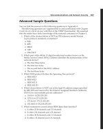
As shown in Figure 18−9, RouterA, RouterB, and RouterC are each connected to a Frame Relay switch. The
Frame Relay switch is a fourth router that is only configured for Frame Relay switching. Each of the three
routers running IPX will be assigned an internal IPX loopback network number. We will see in this lab that
we will be able to learn each of these internal networks over the Frame Relay core.
601
Figure 18−9: IPX over Frame Relay
Router Configuration
The configurations for the routers in this example are as follows (key IPX commands are highlighted in bold).
RouterA
Current configuration:
!
version 11.2
service timestamps debug uptime
service timestamps log uptime
no service password−encryption
no service udp−small−servers
no service tcp−small−servers
!
hostname RouterA
!
enable password cisco
!
ipx routing 0001.0001.0001
!
interface Loopback1
no ip address
ipx network 1
!
interface Serial1/0
encapsulation frame−relay
ipx network 6
no fair−queue
clockrate 800000
frame−relay map ipx 6.0002.0002.0002 102 broadcast ← Frame Relay map
statements are used to
control which DLCIs will
carry traffic
frame−relay map ipx 6.0004.0004.0004 102 broadcast
no frame−relay inverse−arp ← Disable inverse ARP since we are using map
statements
frame−relay lmi−type ansi
!
ipx router eigrp 100
network 6
!
ipx router rip
no network 6
!
line con 0
line aux 0
line vty 0 4
password cisco
login
602
!
end
RouterB
Current configuration:
!
version 11.2
service timestamps debug uptime
service timestamps log uptime
no service password−encryption
no service udp−small−servers
no service tcp−small−servers
!
hostname RouterB
!
enable password cisco
!
ipx routing 0004.0004.0004
!
interface Loopback1
no ip address
ipx network 4
!
interface Serial0/0
encapsulation frame−relay
ipx network 6
no ipx split−horizon eigrp 100 ← RouterB is the hub router. EIGRP split
horizon needs to be disabled on this router
clockrate 800000
frame−relay map ipx 6.0001.0001.0001 102 broadcast
frame−relay map ipx 6.0002.0002.0002 103 broadcast
no frame−relay inverse−arp
frame−relay lmi−type ansi
!
ipx router eigrp 100
network 6
!
ipx router rip
no network 6
!
line con 0
line aux 0
line vty 0 4
password cisco
login
!
end
RouterC
Current configuration:
!
version 11.2
no service password−encryption
no service udp−small−servers
no service tcp−small−servers
!
hostname RouterC
!
enable password cisco
!
ipx routing 0002.0002.0002
!
interface Loopback1
no ip address
603
ipx network 2
!
interface Serial0/0
encapsulation ppp
ipx network 7
!
interface Serial0/1
encapsulation frame−relay
ipx network 6
clockrate 800000
frame−relay map ipx 6.0001.0001.0001 103 broadcast
frame−relay map ipx 6.0004.0004.0004 103 broadcast
no frame−relay inverse−arp
frame−relay lmi−type ansi
!
ipx router eigrp 100
network 6
network 7
!
ipx router rip
no network 6
!
line con 0
line aux 0
line vty 0 4
password cisco
login
!
end
FrameSwitch
Current configuration:
!
version 11.2
no service udp−small−servers
no service tcp−small−servers
!
hostname FrameSwitch
!
!
frame−relay switching
!
interface Serial1/0
no ip address
encapsulation frame−relay
frame−relay lmi−type ansi
frame−relay intf−type dce
frame−relay route 102 interface
!
interface Serial1/1
no ip address
encapsulation frame−relay
frame−relay lmi−type ansi
frame−relay intf−type dce
frame−relay route 102 interface
frame−relay route 103 interface
!
interface Serial1/2
no ip address
encapsulation frame−relay
frame−relay lmi−type ansi
frame−relay intf−type dce
frame−relay route 103 interface
!
no ip classless
!
Serial1/1 102
Serial1/0 102
Serial1/2 103
Serial1/1 103
604
line con 0
line aux 0
line vty 0 4
login
!
end
Monitoring and Testing the Configuration
Let's start by connecting to RouterA. Use the show ipx route command to verify that all of the neighboring
networks are being learned over the Frame Relay core. We see that RouterA is learning IPX Network 2 and
IPX Network 4 via IPX EIGRP.
RouterA#show ipx route
Codes: C − Connected primary network,
c − Connected secondary network
S − Static, F − Floating static, L − Local (internal), W − IPXWAN
R − RIP, E − EIGRP, N − NLSP, X − External, A − Aggregate
s − seconds, u − uses
4 Total IPX routes. Up to 1 parallel paths and 16 hops allowed.
No default route known.
C
C
E
E
1 (UNKNOWN),
Lo1
6 (FRAME−RELAY),
Se1/0
2 [2809856/1] via
6.0004.0004.0004, age 00:43:01,
1u, Se1/0
4 [2297856/1] via
6.0004.0004.0004, age 00:43:57,
1u, Se1/0
Now let's connect to RouterB. RouterB is the hub router in this configuration. Verify with the show ipx route
command that RouterB is learning routes to the other networks in this configuration. We see that RouterB had
learned routes to IPX Network 1 and IPX Network 2 via IPX EIGRP. These are the two loopback networks on
RouterA and RouterC.
RouterB#show ipx route
Codes: C − Connected primary network,
c − Connected secondary network
S − Static, F − Floating static, L − Local (internal), W − IPXWAN
R − RIP, E − EIGRP, N − NLSP, X − External, A − Aggregate
s − seconds, u − uses
4 Total IPX routes. Up to 1 parallel paths and 16 hops allowed.
No default route known.
C
C
E
E
4 (UNKNOWN),
Lo1
6 (FRAME−RELAY),
Se0/0
1 [2297856/1] via
6.0001.0001.0001, age 00:44:26,
6u, Se0/0
2 [2297856/1] via
6.0002.0002.0002, age 00:43:31,
1u, Se0/0
The show ipx eigrp neighbor command on RouterB shows us that RouterB has established EIGRP neighbors
on RouterA (6.0001.0001.0001) and Router C (6.0002.0002.0002).
RouterB#show ipx eigrp neigh
IPX EIGRP Neighbors for process 100
H
Address
Interface
1
0
6.0002.0002.0002
6.0001.0001.0001
Se0/0
Se0/0
Hold Uptime
SRTT
(sec)
(ms)
179 00:44:18
5
175 00:44:39
5
605
RTO
Q
Cnt
200 0
200 0
Seq
Num
21
17
Now connect to RouterC. Verify that routes are being learned to the loopback networks on RouterA and
RouterB. We see below that routes are being learned to IPX Networks 1 and 4:
RouterC#sh
Codes: C −
S −
R −
s −
ipx route
Connected primary network,
c − Connected secondary network
Static, F − Floating static, L − Local (internal), W − IPXWAN
RIP, E − EIGRP, N − NLSP, X − External, A − Aggregate
seconds, u − uses
4 Total IPX routes. Up to 1 parallel paths and 16 hops allowed.
No default route known.
C
C
E
E
2 (UNKNOWN),
Lo1
6 (FRAME−RELAY),
Se0/1
1 [2809856/1] via
6.0004.0004.0004, age 00:10:55,
2u, Se0/1
4 [2297856/1] via
6.0004.0004.0004, age 00:10:55,
1u, Se0/1
Let's verify that we have end−to−end connectivity by trying to ping the IPX loopback interface on RouterA
with the ping ipx 1.1.1.1 command. We see below that the ping is successful:
RouterC#ping ipx 1.1.1.1
Type escape sequence to abort.
Sending 5, 100−byte IPX cisco Echoes to 1.0001.0001.0001, timeout is 2 seconds:
!!!!!
Success rate is 100 percent (5/5), round−trip min/avg/max = 28/29/32 ms
Now connect to RouterB. Go into configuration mode and enable split horizon on interface S0/0.
RouterB(config)#interface Serial0/0
RouterB(config−if)#ipx split−horizon eigrp 100
Reconnect to RouterA. We see from the show ipx route command that RouterA is no longer learning any
routes to the other networks due to split horizon being enabled.
RouterA#show ipx route
Codes: C − Connected primary network,
c − Connected secondary network
S − Static, F − Floating static, L − Local (internal), W − IPXWAN
R − RIP, E − EIGRP, N − NLSP, X − External, A − Aggregate
s − seconds, u − uses
2 Total IPX routes. Up to 1 parallel paths and 16 hops allowed.
No default route known.
C
C
1 (UNKNOWN),
6 (FRAME−RELAY),
Lo1
Se1/0
Lab #85: IPX Dial Backup
Equipment Needed
The following equipment is needed to perform this lab exercise:
• Two Cisco routers. Each router must have one serial interface and one BRI interface.
• One Cisco crossover cable. If a Cisco crossover cable is not available, you can use a Cisco DTE cable
connected to a Cisco DCE cable.
606
• Two ISDN BRI cables.
• A Cisco rolled cable for console port connection to the routers.
• Cisco IOS image that supports the IPX protocol.
• Two ISDN BRI circuits.
Configuration Overview
This lab will demonstrate how to configure a router for IPX dial backup using an IPX floating static route. An
IPX floating static route appears in the IPX routing table as a default route. It will not be used unless a route to
a given destination does not exist.
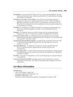
The two routers are connected as shown in Figure 18−10. RouterA acts as a DCE and supplies clocking to
RouterB.
Figure 18−10: IPX dial backup
ISDN Switch Setup
If you do not have access to actual ISDN circuits, you can use an ISDN desktop switch. For this lab we used
an Adtran Atlas 800. Information on configuring the Adtran Atlas 800 switch can be found in Chapter 3.
Router Configuration
The configurations for the routers in this example are as follows (key IPX dial backup commands are
highlighted in bold).
RouterA
Current configuration:
!
version 12.1
service timestamps debug uptime
service timestamps log uptime
no service password−encryption
!
hostname RouterA
!
!
username RouterB password 0 cisco
!
!
ip subnet−zero
!
lane client flush
ipx routing 000a.000a.000a
isdn switch−type basic−ni ← Set the ISDN switch type
cns event−service server
!
!
interface Loopback0
no ip address
ipx network 1
!
607
interface Serial0/0
no ip address
encapsulation ppp
ipx network 3
no fair−queue
clockrate 800000
!
interface BRI1/0
no ip address
encapsulation ppp
dialer map ipx 4.000b.000b.000b name RouterB broadcast 8995201 ← Configure the
dialer map
dialer load−threshold 255 either ← Set the load threshold to the maximum limit
so only one B channel will be used to make
our calls
dialer−group 1 ← Assign this interface to dialer group 1
ipx network 4
isdn switch−type basic−ni
isdn spid1 5101 8995101 ← Set the SPID values for the ISDN circuit
isdn spid2 5102 8995102
ppp authentication chap
!
ip classless
no ip http server
!
access−list 900 permit any any cping ← Access list 900 defines interesting
traffic
access−list 900 deny rip
access−list 900 permit any any
dialer−list 1 protocol ipx list 900 ← Define interesting traffic parameters
!
!
ipx route default 4.000b.000b.000b floating−static ← Configure the IPX floating
static route
!
ipx router eigrp 1
network 3
!
!
ipx router rip
no network 3
!
!
line con 0
transport input none
line aux 0
line vty 0 4
login
!
end
RouterB
Current configuration:
!
version 12.1
service timestamps debug uptime
service timestamps log uptime
no service password−encryption
!
hostname RouterB
!
!
username RouterA password 0 cisco
!
!
ip subnet−zero
608
!
lane client flush
ipx routing 000b.000b.000b
isdn switch−type basic−ni
cns event−service server
!
!
interface Loopback0
no ip address
ipx network 2
!
interface Serial0/0
no ip address
encapsulation ppp
ipx network 3
!
interface BRI1/0
no ip address
encapsulation ppp
dialer map ipx 4.000a.000a.000a name RouterA broadcast
dialer load−threshold 1 either
dialer−group 1
ipx network 4
isdn switch−type basic−ni
isdn spid1 5201 8995201
isdn spid2 5202 8995202
ppp authentication chap
!
ip classless
no ip http server
!
access−list 900 permit any any cping
access−list 900 deny rip
dialer−list 1 protocol ipx list 900
!
!
ipx router eigrp 1
network 3
network 2
!
!
ipx router rip
no network 2
no network 3
!
!
line con 0
transport input none
line aux 0
line vty 0 4
login
!
end
Monitoring and Testing the Configuration
Let's start by connecting to RouterA. The show isdn status command indicates that the ISDN circuit has been
properly configured. Notice that both SPIDs have been sent to the ISDN switch and validated.
RouterA#show isdn status
Global ISDN Switchtype = basic−ni
ISDN BRI1/0 interface
dsl 8, interface ISDN Switchtype = basic−ni
Layer 1 Status:
ACTIVE
Layer 2 Status:
609
TEI = 64, Ces = 1, SAPI = 0, State = MULTIPLE_FRAME_ESTABLISHED
TEI = 65, Ces = 2, SAPI = 0, State = MULTIPLE_FRAME_ESTABLISHED
TEI 64, ces = 1, state = 8(established)
spid1 configured, spid1 sent, spid1 valid
Endpoint ID Info: epsf = 0, usid = 70, tid = 1
TEI 65, ces = 2, state = 8(established)
spid2 configured, spid2 sent, spid2 valid
Endpoint ID Info: epsf = 0, usid = 70, tid = 2
Layer 3 Status:
0 Active Layer 3 Call(s)
Activated dsl 8 CCBs = 0
The Free Channel Mask: 0x80000003
Total Allocated ISDN CCBs = 0
We see from the show ipx route command that RouterA is learning about the loopback interface (IPX
Network 2) on RouterB via IPX EIGRP. We also see that that IPX Network 2 is being learned via IPX
Network 3 (the serial link between RouterA and RouterB). Notice that the IPX routing table also contains an
entry for the floating static route that we defined. Since this is an IPX floating static route, it will not be
installed in the routing table unless no other routes to a given destination exist.
RouterA#show ipx route
Codes: C − Connected primary network,
c − Connected secondary network
S − Static, F − Floating static, L − Local (internal), W − IPXWAN
R − RIP, E − EIGRP, N − NLSP, X − External, A − Aggregate
s − seconds, u − uses, U − Per−user static
5 Total IPX routes. Up to 1 parallel paths and 16 hops allowed.
Current default route is:
F
C
C
C
E
FFFFFFFE via
1
3
4
2
BR1/0 ← Floating static route
4.000b.000b.000b,
(UNKNOWN),
Lo0
(PPP),
Se0/0
(PPP),
BR1/0
[1889792/0] via
3.000b.000b.000b, age 00:33:57,
1u, Se0/0
Now connect to RouterB. Use the show isdn status command to verify that the ISDN circuit is ready to
receive a call. We see that both spids have been successfully sent to the ISDN switch.
RouterB#show isdn status
Global ISDN Switchtype = basic−ni
ISDN BRI1/0 interface
dsl 8, interface ISDN Switchtype = basic−ni
Layer 1 Status:
ACTIVE
Layer 2 Status:
TEI = 64, Ces = 1, SAPI = 0, State = MULTIPLE_FRAME_ESTABLISHED
TEI = 65, Ces = 2, SAPI = 0, State = MULTIPLE_FRAME_ESTABLISHED
TEI 64, ces = 1, state = 5(init)
spid1 configured, spid1 sent, spid1 valid
Endpoint ID Info: epsf = 0, usid = 70, tid = 1
TEI 65, ces = 2, state = 5(init)
spid2 configured, spid2 sent, spid2 valid
Endpoint ID Info: epsf = 0, usid = 70, tid = 2
Layer 3 Status:
0 Active Layer 3 Call(s)
Activated dsl 8 CCBs = 0
The Free Channel Mask: 0x80000003
Total Allocated ISDN CCBs = 0
Now reconnect to RouterA. Enable PPP authentication and dialer debugging with the debug ppp
authentication and debug dialer commands.
610
RouterA#debug ppp authentication
PPP authentication debugging is on
RouterA#debug dialer
Dial on demand events debugging is on
Now we will start an extended ping from RouterA to the loopback interface of RouterB. After the ping has
started, the serial cable connecting RouterA to RouterB should be disconnected.
RouterA#ping
Protocol [ip]: ipx
Target IPX address: 2.b.b.b
Repeat count [5]: 1000
Datagram size [100]: 1500
Timeout in seconds [2]:
Verbose [n]:
Type escape sequence to abort.
Sending 10000, 1500−byte IPX Novell Echoes to 2.000b.000b.000b, timeout is 2 seconds:
!!!!!!!!!!!!!!!!!!!!!!!!!!!!!!!!!!!!!!!!!!!!!!!!!!!!!!!!!!!!!!!!!!!!!!
!!!!!!!!!!!!!!!!!!!!!!!!!!!!!!!!!!!!!!!!!!!!!!!!!!!!!!!!!!!!!!!!!!!!!!
!!!!!!!!!!..
á
After the ping from RouterA to RouterB has begun, pull the serial cable connecting
RouterA to RouterB. When the cable is pulled, the ping will start to fail
After the serial cable is disconnected, the ping will begin to fail. If PPP authentication debugging is enabled,
the following output will be seen, indicating that RouterA is placing an ISDN call to RouterB:
02:48:43: BR1/0 DDR: Dialing cause ipx (s=4.000a.000a.000a, d=2.000b.000b.000b)
02:48:43: BR1/0 DDR: Attempting to dial 8995201
02:48:43: %LINK−3−UPDOWN: Interface Serial0/0, changed state to down
02:48:43: %LINK−3−UPDOWN: Interface BRI1/0 :1, changed state to up
02:48:43: BR1/0:1 PPP: Treating connection as a callout
02:48:43: BR1/0:1 CHAP: O CHALLENGE id 9 len 28 from "RouterA"
02:48:43: BR1/0:1 CHAP: I CHALLENGE id 9 len 28 from "RouterB"
02:48:43: BR1/0:1 CHAP: O RESPONSE id 9 len 28 from "RouterA"
02:48:43: BR1/0:1 CHAP: I SUCCESS id 9 len 4
02:48:43: BR1/0:1 CHAP: I RESPONSE id 9 len 28 from "RouterB"
02:48:43: BR1/0:1 CHAP: O SUCCESS id 9 len 4
02:48:43: BR1/0:1 DDR: dialer protocol up
02:48:44: %LINEPROTO−5−UPDOWN: Line protocol on Interface Serial0/0, changed state to down
02:48:44: %LINEPROTO−5−UPDOWN: Line protocol on Interface BRI1/0:1, changed state to up
02:48:49: %ISDN−6−CONNECT: Interface BRI1/0 :1 is now connected to 8995201 RouterB
Once the ISDN circuit is established, the ping will start to pass once again
↓
!!!!!!!!!!!!!!!!!!!!!!!!!!!!!!!!!!!!!!!!!!!!!!!!!!!!!!!!!!!!!!!!!!!!!!
!!!!!!!!!!!!!!!!!!.
Success rate is 99 percent (576/579), round−trip min/avg/max = 32/121/388 ms
When the ping has completed, check the routing table with the show ipx route command. We see below that
RouterA is now learning about the loopback network (IPX Network 2) on RouterB via IPX RIP over the
ISDN interface:
RouterA#show ipx route
Codes: C − Connected primary network,
c − Connected secondary network
S − Static, F − Floating static, L − Local (internal), W − IPXWAN
R − RIP, E − EIGRP, N − NLSP, X − External, A − Aggregate
s − seconds, u − uses, U − Per−user static
4 Total IPX routes. Up to 1 parallel paths and 16 hops allowed.
Current default route is:
F
FFFFFFFE via
4.000b.000b.000b,
BR1/0
611
C
1 (UNKNOWN),
Lo0
C
4 (PPP),
BR1/0
R
2 [07/01] via
4.000b.000b.000b,
32s, BR1/0
á
RouterA now learns about RouterB's loopback interface via IPX RIP over the ISDN interface
Now reconnect the serial cable between RouterA and RouterB. After the ISDN idle timer expires, the ISDN
call will be disconnected.
02:52:45: %ISDN−6−DISCONNECT: Interface BRI1/0:1 disconnected from
8995201 RouterB, call lasted 119 seconds
02:52:45: %LINK−3−UPDOWN: Interface BRI1/0 :1, changed state to down
02:52:45: BR1/0 :1 DDR: disconnecting call
02:52:46: %LINEPROTO−5−UPDOWN: Line protocol on Interface BRI1/0 :1, changed state to down
After the ISDN call is disconnected, check the routing table with the show ipx route command. We see that
RouterA is once again learning about RouterB's loopback interface via the serial cable connecting RouterA
and RouterB.
RouterA#show ipx route
Codes: C − Connected primary network,
c − Connected secondary network
S − Static, F − Floating static, L − Local (internal), W − IPXWAN
R − RIP, E − EIGRP, N − NLSP, X − External, A − Aggregate
s − seconds, u − uses, U − Per−user static
5 Total IPX routes. Up to 1 parallel paths and 16 hops allowed.
Current default route is:
F
C
C
C
E
FFFFFFFE via
1
3
4
2
4.000b.000b.000b,
BR1/0
(UNKNOWN),
Lo0
(PPP),
Se0/0
(PPP),
BR1/0
[1889792/0] via
3.000b.000b.000b, age 00:01:56,
1291u, Se0/0
IPX Monitoring and Troubleshooting Commands
This section will discuss key IPX monitoring and troubleshooting commands.
{show ipx interface brief} The show ipx interface brief command can be used to get a quick snapshot of
the state of all interfaces on a router that are running the IPX protocol.
RouterA#show ipx interface brief
Interface
IPX Network
Ethernet0/0
1
Serial0/0
2
Loopback0
5
Encapsulation
NOVELL−ETHER
PPP
UNKNOWN
Status
up
up
up
IPX State
[up]
[up]
[up]
{show ipx route} Typing the show ipx route command displays the routing table for this router. This routing
table shows us that three IPX networks are directly connected: Network 1 is on Ethernet0, Network 2 is on
Serial 0, and Network 5 is on Loopback 0. RouterA has learned about two networks via the IPX RIP routing
protocol. Network 3 is 1 hop and 7 ticks away, and Network 4 is 2 hops and 13 ticks away.
RouterA#show ipx route
Codes: C − Connected primary network,
c − Connected secondary network
S − Static, F − Floating static, L − Local (internal), W − IPXWAN
R − RIP, E − EIGRP, N − NLSP, X − External, A − Aggregate
s − seconds, u − uses
5 Total IPX routes. Up to 1 parallel paths and 16 hops allowed.
612
No default route known.
C
C
C
1 (NOVELL−ETHER),
2 (PPP),
5 (UNKNOWN),
Et0/0
Se0/0
Lo0
R
Tick count
Next hop address
↓
↓
3 [07/01] via
2.000b.000b.000b,
á
Hop count to destination network
R
Tick count
Next hop address
↓
↓
4 [13/02] via
2.000b.000b.000b,
á
Hop count to destination network
49s, Se0/0
50s, Se0/0
{show interface} When running IPX, there are two show interface commands that refer to the interface. The
show interface command will show what link control protocols have been negotiated and opened. Traffic
information and lead state status for the interface will also be displayed.
RouterA#show int s 0/0
Serial0/0 is up, line protocol is up
Hardware is QUICC Serial
MTU 1500 bytes, BW 1544 Kbit, DLY 20000 usec, rely 255/255, load 1/255
Encapsulation PPP, loopback not set, keepalive set (10 sec)
LCP Open
Open: CDPCP, IPXCP ← No IP is enabled on this interface
Last input 00:00:01, output 00:00:01, output hang never
Last clearing of "show interface" counters never
Queueing strategy: fifo
Output queue 0/40, 0 drops; input queue 0/75, 0 drops
5 minute input rate 0 bits/sec, 0 packets/sec
5 minute output rate 0 bits/sec, 0 packets/sec
99 packets input, 3888 bytes, 0 no buffer ← Packet's input
Received 99 broadcasts, 0 runts, 0 giants, 0 throttles
0 input errors, 0 CRC, 0 frame, 0 overrun, 0 ignored, 0 abort
100 packets output, 3902 bytes, 0 underruns ← Packet's output
0 output errors, 0 collisions, 16 interface resets
0 output buffer failures, 0 output buffers swapped out
31 carrier transitions
DCD=up DSR=up DTR=up RTS=up CTS=up
{show ipx interface} Specific IPX information for an interface running the IPX protocol can be displayed
with the show ipx int s 0/0 command. This command shows the IPX address of the interface as well as IPX
routing, filtering, and SAP information.
RouterA#show ipx int s 0/0
Serial0/0 is up, line protocol is up
IPX address is 2.000a.000a.000a [up] ← IPX address
A WAN interface has a default IPX delay of 6
↓
Delay of this IPX network, in ticks is 6 throughput 0 link delay 0
IPXWAN processing not enabled on this interface.
IPX SAP update interval is 1 minute(s)
IPX type 20 propagation packet forwarding is disabled
Incoming access list is not set
Outgoing access list is not set
IPX helper access list is not set
SAP GNS processing enabled, delay 0 ms, output filter list is not set
SAP Input filter list is not set
SAP Output filter list is not set
SAP Router filter list is not set
Input filter list is not set
613
Output filter list is not set
Router filter list is not set
Netbios Input host access list is not set
Netbios Input bytes access list is not set
Netbios Output host access list is not set
Netbios Output bytes access list is not set
Updates each 60 seconds, aging multiples RIP: 3 SAP: 3
SAP interpacket delay is 55 ms, maximum size is 480 bytes
RIP interpacket delay is 55 ms, maximum size is 432 bytes
Watchdog processing is disabled, SPX spoofing is disabled, idle time 60
IPX accounting is disabled
IPX fast switching is configured (enabled)
RIP packets received 9, RIP packets sent 9 ← RIP is running on this interface
SAP packets received 1, SAP packets sent 1 ← SAP is running on this interface
{ping ipx} IPX is limited in its diagnostic capabilities as compared to IP. With IPX, the only tool available to
test network connectivity is the ping ipx command.
RouterA#ping ipx 2.b.b.b ← ping RouterB
Type escape sequence to abort.
Sending 5, 100−byte IPX cisco Echoes to 2.000b.000b.000b, timeout is 2 seconds:
!!!!!
Success rate is 100 percent (5/5), round−trip min/avg/max = 28/29/32 ms
{show ipx traffic} The show ipx traffic command displays IPX traffic information for all interfaces on the
router. User traffic, routing protocols, and SAP statistics are displayed.
RouterC#show ipx traffic
System Traffic for 0.0000.0000.0001 System−Name: RouterC
Rcvd:
36 total, 0 format errors, 0 checksum errors, 0 bad hop count,
0 packets pitched, 36 local destination, 0 multicast
Bcast: 16 received, 29 sent
Sent:
50 generated, 0 forwarded
0 encapsulation failed, 0 no route
SAP:
1 SAP requests, 0 SAP replies, 0 servers
0 SAP Nearest Name requests, 0 replies
0 SAP General Name requests, 0 replies
5 SAP advertisements received, 4 sent
2 SAP flash updates sent, 0 SAP format errors
RIP:
1 RIP requests, 0 RIP replies, 5 routes
9 RIP advertisements received, 18 sent
2 RIP flash updates sent, 0 RIP format errors
Echo:
Rcvd 5 requests, 15 replies
Sent 15 requests, 5 replies
0 unknown: 0 no socket, 0 filtered, 0 no helper
0 SAPs throttled, freed NDB len 0
Watchdog:
0 packets received, 0 replies spoofed
Queue lengths:
IPX input: 0, SAP 0, RIP 0, GNS 0
SAP throttling length: 0/(no limit), 0 nets pending lost route reply
Delayed process creation: 0
EIGRP: Total received 0, sent 0
Updates received 0, sent 0
Queries received 0, sent 0
Replies received 0, sent 0
SAPs received 0, sent 0
NLSP:
Level−1 Hellos received 0, sent 0
PTP Hello received 0, sent 0
Level−1 LSPs received 0, sent 0
LSP Retransmissions: 0
LSP checksum errors received: 0
LSP HT=0 checksum errors received: 0
Level−1 CSNPs received 0, sent 0
Level−1 PSNPs received 0, sent 0
614
Level−1 DR Elections: 0
Level−1 SPF Calculations: 0
Level−1 Partial Route Calculations: 0
{show ipx eigrp neighbor} The show ipx eigrp neighbor command will display information on what
neighboring EIGRP routers have been discovered.
RouterA#show ipx eigrp neigh
IPX EIGRP Neighbors for process 1
H
Address
Interface
0
2.000b.000b.000b
Se0/0
Hold Uptime
SRTT
(sec)
(ms)
13 02:10:19
53
RTO
Q Seq
Cnt Num
318 0 38
{show ipx eigrp interfaces} The show ipx eigrp interfaces command will show what router interfaces are
running EIGRP.
RouterA#show ipx eigrp interfaces
IPX EIGRP Interfaces for process 1
Xmit Queue
Interface
Peers Un/Reliable
Se0/0
1
0/0
á
Interface S0/0 is running EIGRP
Mean
SRTT
53
Pacing Time
Un/Reliable
0/15
Multicast
Flow Timer
263
Pending
Routes
0
{show ipx eigrp traffic} The show ipx eigrp traffic command is a useful command that shows how much
EIGRP traffic has been sent and received on the router.
RouterB#show ipx eigrp traffic
IP−EIGRP Traffic Statistics for process 1
Hellos sent/received: 3433/3430
Updates sent/received: 11/11
Queries sent/received: 10/7
Replies sent/received: 7/10
Acks sent/received: 37/33
Input queue high water mark 2, 0 drops
{show ipx servers} The show ipx servers command will display any servers that have either been statically
defined on the router or learned via SAP updates.
RouterA#show ipx servers
Codes: S − Static, P − Periodic, E − EIGRP, N − NLSP, H − Holddown, + = detail
1 Total IPX Servers
Table ordering is based on routing and server info
S
Type Name
4 Server4
Net
Address
Port
4.00e0.1e5b.0a81:0451
Route Hops
2707456/01
Itf
2 Se0/0
{show access−list} The show access−list command is used to display information on access lists that have
been defined on the router.
RouterB#show access−list
IPX SAP access list 1000 ← Access list 1000
deny FFFFFFFF 7 Server2 ← Do not sent any updates to any network regarding
IPX Server2 with a server type of 7
permit FFFFFFFF ← Permit SAP updates to all other networks
{debug ipx routing activity}
615
{debug ipx routing events} The debug ipx routing activity and debug ipx routing events commands
display information on IPX RIP routing protocol activity.
RouterB#debug ipx routing activity
IPX routing debugging is on
RouterB#debug ipx routing events
IPX routing events debugging is on
{debug ipx sap activity}
{debug ipx sap events} The debug ipx sap activity and debug ipx sap events commands will display
information SAP packets being sent or received on the router.
RouterC#debug ipx sap activity
IPX service debugging is on
RouterC#debug ipx sap events
IPX service events debugging is on
Conclusion
This chapter explored the Novell IPX networking protocol. Although it is declining in popularity, Novell IPX
is still in widespread use. The hands−on labs in this chapter explored key Novell IPX topics such as
• Basic IPX configuration and monitoring
• IPX EIGRP configuration
• IPX static SAP entries
• IPX SAP and router filtering capabilities
• Configuring IPX over a Frame Relay core
• IPX dial backup with PPP callback
616
Chapter 19: AppleTalk
Overview
Topics Covered in This Chapter
• AppleTalk technology overview
• Cisco AppleTalk support
• AppleTalk EIGRP configuration
• AppleTalk GRE tunnels
• AppleTalk traffic filtering
• AppleTalk Zone filtering
• AppleTalk over Frame Relay
• AppleTalk dial backup with floating static routes
• Troubleshooting AppleTalk networks
Introduction
AppleTalk is a networking protocol developed by Apple Computer to provide networking services for its
Macintosh computers. AppleTalk is the most automatic of all the desktop protocols, but it is also the chattiest.
For example, the default routing protocol for AppleTalk is RTMP. RTMP sends routing updates every 10
seconds to all directly connected neighbors.
AppleTalk Terminology
An AppleTalk node can be any device that is connected to an AppleTalk network and is assigned an
AppleTalk address. Nodes can be Macintosh computers, printers, or any other device that resides on the
network and is addressable.
An AppleTalk network can be thought of as a physical LAN or WAN that contains one or more AppleTalk
nodes.
An AppleTalk zone is a logical group of networks. A zone will usually consist of AppleTalk nodes that reside
in different physical locations. Zones are very similar in concept to a virtual LAN. In Figure 19−1 we see an
example of how AppleTalk zones can work. Figure 19−1 shows an AppleTalk network with three Ethernet
segments. The Ethernet segments on RouterA and RouterB are both in zone Engineering. When a Macintosh
user on the Ethernet LAN connected to RouterC wants to access resources in the Engineering zone, he or she
is given access to the LAN on RouterA and RouterB. Zones allow you to functionally group network
resources without any regard to their actual physical location.
617
Figure 19−1: Improper AppleTalk address range
AppleTalk Addressing
Early AppleTalk networks were referred to as Phase I or nonextended networks. Phase I networks had a
limited address space. Each LAN or WAN segment was allowed to contain up to 127 hosts and up to 127
servers. Each LAN or WAN segment could only be assigned a single AppleTalk network number.
AppleTalk Phase II networks are much more flexible in their network addressing. A Phase II network allows
multiple network numbers to exist on each network segment. This means that a LAN can contain multiple
AppleTalk networks. The range of network numbers that exist on a network segment is referred to as the
cable range of the segment. The cable range must be unique and cannot overlap with other router interfaces.
Figure 19−1 shows an example of an AppleTalk network with improperly assigned cable range numbers. In
the case of Figure 19−1, there is an address conflict since network 498 has been assigned to both Ethernet
LANs. Figure 19−2 shows a properly configured AppleTalk network — there are no address overlaps.
Figure 19−2: Proper AppleTalk address assignment
AppleTalk node address assignment is designed to minimize the amount of configuration needed on a
Macintosh computer. When a Macintosh is first powered on, it sends a broadcast to any routers on the same
network segment asking what the cable range of the network segment is. Once a router responds, the
Macintosh chooses a network number within the cable range. The Macintosh then picks a node number.
Before the AppleTalk node uses the network.node combination it has picked, it queries the network to see if
the network.node combination is already in use. If the address is already used, it will continue to choose new
addresses until an unused address has been found.
As shown in Figure 19−3, an AppleTalk address is 24 bits long. The address is written in a network.node
format. The first 16 bits are the network number and the last eight bits are the node number. This means that
all AppleTalk networks will be numbered less than 65,536 and all AppleTalk nodes will be numbered less
than 256. Node numbers 0 and 255 are reserved (255 is used as a network broadcast address). An AppleTalk
network can therefore have 254 nodes per network.
Figure 19−3: AppleTalk address structure
AppleTalk Protocol Stack
Figure 19−4 shows the AppleTalk stack and its relationship to the OSI stack.
618
Figure 19−4: AppleTalk protocol stack
Physical and Datalink Layers
In addition to being supported on WAN links such as frame relay and ISDN, AppleTalk is supported on four
major LAN platforms:
• EtherTalk: Apple's version of Ethernet.
• TokenTalk: Apple's version of token ring.
• FDDITalk: Apple's version of FDDI.
• AppleTalk: An Apple proprietary serial link that runs at 230Kbps.
Network Layer
AppleTalk uses the Datagram Delivery Protocol (DDP) at the network layer for routing packets in a network.
AppleTalk is a routable protocol since it has a network layer address associated with each AppleTalk node.
DDP is a connectionless network protocol. Figure 19−5 shows the DDP packet header in more detail.
Figure 19−5: DDP packet
Transport Layer
Several protocols exist in the AppleTalk transport layer:
• Routing Table Maintenance Protocol (RTMP): A distance vector routing protocol that is similar to
IP RIP. RTMP is very chatty. It sends out a routing update to all connected neighbors every 10
seconds.
• AppleTalk Echo Protocol (AEP): AEP is a simple protocol that generates packets that can be used
to test the reachability of various network nodes.
• AppleTalk Transaction Protocol (ATP): ATP provides connection−based data transfer for
AppleTalk traffic. It functions in a similar mode to TCP in an IP network. ATP provides for data
619
acknowledgment, retransmission, packet sequencing, and fragmentation and reassembly.
• NBP: The Name Binding Protocol associates an AppleTalk name with an address.
Session Layer
AppleTalk supports several upper−layer protocols:
• AppleTalk Session Protocol (ASP): ASP establishes and maintains sessions between an AppleTalk
client and a server.
• Zone Information Protocol: The Zone Information Protocol maintains network number to zone
name mappings in zone information tables. ZIP uses RTMP routing tables to keep up with network
topology changes. When ZIP finds a routing table entry that is not in the ZIP, it creates a new ZIP
entry.
• AppleTalk Printer Access Protocol (PAP): PAP is a connection−oriented protocol that establishes
and maintains connections between clients and printers.
Application/Presentation Layer
The AppleTalk Filing Protocol (AFP) helps clients share server files across a network.
AppleTalk Routing Protocols
Cisco supports three routing protocols for AppleTalk networks:
• RTMP: The Routing Table Maintenance Protocol is enabled by default on an AppleTalk network.
RTMP is a distance vector routing protocol that uses hop count as its metric. The update period for
RTMP is every 10 seconds regardless of whether or not there was a change in the network. This
frequent update has the effect of producing a large amount of routing traffic on an AppleTalk
network.
• AURP: AppleTalk Update−Based Routing Protocol (AURP) is a routing protocol similar to RTMP
in that it is a distance vector routing protocol with a maximum hop count of 15 hops. AURP differs
from RTMP in that it only sends routing updates when a change has occurred in the network, RTMP
sends updates every 10 seconds. AURP is also a tunneling protocol, which allows AppleTalk to be
tunneled in TCP/IP, thus allowing two AppleTalk networks to be connected over a TCP/IP network.
The TCP/IP connection is called a "tunnel" and is counted as one network hop. The router that
connects an AppleTalk network to a tunnel is referred to as an exterior router.
• EIGRP: AppleTalk EIGRP is used mainly for WAN links in an AppleTalk network. AppleTalk
EIGRP uses the same composite metric that IP and IPX EIGRP use. AppleTalk EIGRP also uses the
same DUAL routing algorithm, only sending out routing updates when a change has occurred in the
network. AppleTalk EIGRP differs from IP and IPX EIGRP in that the autonomous system number
used to start the routing process must be unique for each router. AppleTalk EIGRP features automatic
redistribution with the RTMP routing protocol.
AppleTalk Zones
An AppleTalk zone is a grouping of similar resources. It is very similar in concept to a Virtual LAN (VLAN).
Each AppleTalk network must be defined to be a member of one or more zones. The AppleTalk Zone
Information Protocol (ZIP) maintains a listing of all zone names and associated AppleTalk network numbers
for the entire network. Members of a particular zone can be located anywhere in the entire network. Let's look
at what will happen when an AppleTalk node such as an Apple Macintosh needs a service such as a printer:
1. The Macintosh chooser will send a request to the local router for a list of all zones.
2. The Macintosh looks in the list of zones for the appropriate service.
3. If the appropriate service is found, the Macintosh will send a request to each of the cable numbers in
the selected zone.
620