CCNP ISCW Official Exam Certification Guide phần 2 doc
Bạn đang xem bản rút gọn của tài liệu. Xem và tải ngay bản đầy đủ của tài liệu tại đây (1.54 MB, 68 trang )
38 Chapter 2: Topologies for Teleworker Connectivity
Remote Connection Options
The enterprise architecture framework, and therefore the Cisco SRND for teleworkers,
emphasizes a few ideas for the overall solution. These ideas are the primary goals of the solution:
■ Defining safe boundaries within which the solution may be deployed (facilitated by proper
expectation setting). That is, the solution must maintain the security standards of the
corporation to avoid or mitigate exposure. The teleworker must agree to be bound by
corporate security policies in the residential office.
■ Providing hardware and software recommendations for a given deployment model
■ Including or referencing performance and configuration information
These goals are meant to allow the extension of integrated services to teleworker homes in a safe,
secure manner while maintaining a comparable service level to that provided to campus-based
employees. The overall goal is similar to that of the other architectures put forth by SONA,
including protection, cost reduction, and scalable growth potential.
Remote connectivity is not without its challenges, obviously. For each challenge, innovation has
brought forth new possibilities for connectivity. Regardless of the chosen option, the common
theme still rings true, “Design today with tomorrow in mind.” Some of the available options for
remote connectivity are as follows:
■ Traditional Layer 2 technologies such as Frame Relay, ATM, or leased lines
■ Service provider MPLS VPNs offering scalable, flexible, and fully meshed connections
■ Site-to-site and remote-access IPsec VPNs over the public Internet
Each of these options could easily be selected and expected to fully serve the basic needs of the
remote site or employee. However, each comes with its own challenges where the balance of cost
versus security is concerned.
Traditional Layer 2 Connections
Traditional Layer 2 connections such as Frame Relay and ATM are, most importantly, not
available to residential premises (typically). Also, the nature of a Layer 2 connection does not
provide much in the way of QoS configuration beyond basic traffic shaping over the link. This
aspect alone might be enough to disqualify it as an option if it were available to the teleworker
premise. However, these technologies tend to be quite secure, even if there is near-total reliance
on the service provider for that security.
150x01x.book Page 38 Monday, June 18, 2007 8:52 AM
Facilitating Remote Connections 39
Service Provider MPLS VPN
MPLS VPNs, as a technology, tend to be the preferred method of the day. The nature of the
technology is to provide Layer 3, any-to-any connectivity throughout the network in a secure
manner. A similar Layer 2 deployment would prove to be cost prohibitive simply due to the
number of circuits required. This is where MPLS shines. A single circuit provides the needed
connectivity for all sites. MPLS networks allow the extension of enterprise QoS across the service
provider network and the honoring of service levels dictated therein. This alone is a tremendous
step forward in the quest for the IIN. There is a bit of confusion associated with VPNs however.
The confusion comes in the service provider’s specific implementation. At what point is the traffic
flow being tagged and protected according to established QoS policies? This is a bit of a sticking
point because it varies from provider to provider. At the time of this writing, the majority of
providers are still backhauling traffic to their core prior to any tagging or traffic classification. The
chapters in Part II, “Implementing Frame Mode MPLS,” discuss this in more detail. For now,
suffice to say that, prior to selecting a service provider, you should take precautions and ask in-
depth questions regarding QoS policies.
Site-to-Site VPN over Public Internet
This solution tends to be the most prevalent for teleworker solutions, because the Layer 2 and
Layer 3 technologies previously mentioned are more appropriate for campus-to-branch
connectivity and typically are not available to a residence (due to cost and/or availability). The
site-to-site VPN solution tends to have the highest volume of security-related considerations as
well, due to its contact with the public Internet.
The use of the Internet as a transport for VPN connections back to the campus or central site is
likely the most feasible and cost effective due to the widespread broadband capabilities available
(and already installed) in most homes. This allows the corporation to avoid taking on the actual
cost of the connection, if so desired, while enabling it to easily provide secure connectivity back
to the central site.
The manner in which that is accomplished, however, is open to debate based on the needs of the
user and the nature of the connection. Is the connection to be transparent to the user in the form of
a nailed-up VPN connection established by a router placed in the home? Or, is that connection
going to be one established by the use of a VPN client launched from a laptop on an as-needed
basis? Each is a viable solution.
NOTE MPLS, being a Layer 3 technology, still requires a Layer 2 technology for connectivity
at the local loop. This is most often accomplished with a Frame Relay connection from the CPE
to the provider ingress edge.
150x01x.book Page 39 Monday, June 18, 2007 8:52 AM
40 Chapter 2: Topologies for Teleworker Connectivity
Challenges of Connecting Teleworkers
In maintaining position on the path to IIN, it should be noted that some sections of the map are
more mature and well-traveled than others, meaning that there is greater detail available. The
industry experience with providing multiple enhanced functions to teleworker devices is at a
relatively early stage. The enterprise teleworker solution provides an always-on (potentially),
secure, and centrally managed connection to business resources and services. In keeping with
established goals, this should provide services and applications identical to those available to users
based in campus and/or branch sites. In doing so, a number of requirements spring forth:
■ Continuity of operation in case of loss of access to the workplace network (that is, home
broadband connection outage)
■ Comparable network application responsiveness across geographical, functional, business,
and/or decision-making boundaries—or, more to the point, one experience regardless of
locale
■ Secure, reliable access to critical applications and services necessary for job function
fulfillment
■ Cost-effective extension of data, voice, video, and real-time applications and services over a
common (and sometimes best-effort) network connection
■ Increased employee productivity, satisfaction, and retention
Recommended practice dictates that targeted pilots be used to streamline the solution and
document the process of its implementation to a very high degree. In all honesty, the use of
network administration personnel as guinea pigs is advocated and applauded in such cases.
Consider the fact that the corporate network is being extended to co-exist with the user’s home
network. The corporation has no control whatsoever over the traffic flow habits in the home
network. A careless teleworker can easily compromise the security of a corporate network
infrastructure. In that, there are associated risks and potential for breach of security. This is the
case for both wired and wireless home networks.
All functionality to be deployed at the home should be thoroughly tested before deployment. This
includes security, data connectivity, and, most importantly, voice and video quality. This will allow
the tweaking of the solution for improved quality of each prior to wide-scale deployment. Most
network applications will perform well over the network within the corporate office. These same
applications might not do quite so well in a teleworker deployment, however, due to the simple,
yet chaotic, nature of the Internet. In any intrinsically latent network, you must take care to
thoroughly test any proposed solution.
150x01x.book Page 40 Monday, June 18, 2007 8:52 AM
Challenges of Connecting Teleworkers 41
Infrastructure Options
Consider the number of applications used daily by the typical network user. It doesn’t take long
for the application count to get into double-digits. That said, now consider those applications and
services that are actually relevant to the business at hand for a given job position or function,
specifically those applications and services that are critical for one to do the job for which they
were hired. Once again, it remains rather easy to get to a significant number of items on the list.
What options are available that will allow these applications and services to be accessed from
varying degrees of connectivity? For purposes of discussion, keep the idea of “varying degrees of
connectivity” limited to those available to the home. The plight of the road warrior is a discussion,
though no less important, for a later time.
One of the early considerations in constructing a solution must be the access methodology and
bandwidth afforded by said methodology. Three somewhat prevalent methods come to mind as
having the widest availability currently:
■ Cable
■ DSL
■ Fiber optic access
Each offers relatively high bandwidth capabilities to the user community. By far, fiber optic
solutions offer the highest bandwidth (ranging from 5 to 30 Mbps downstream, 2 to 5 Mbps
upstream and climbing), dwarfing cable and DSL capabilities. Cable and DSL are in heavy
competition, providing nearly equivalent bandwidth (1.5 to 10 Mbps downstream; upstream
varies) in most markets. The typical mid-range fiber optic offering is roughly equivalent in price
to the high-end price of DSL and cable at 5 to 6 Mbps. However, it should be said that cable has
excellent prospects for future development. Some providers are offering 25 Mbps downstream
speeds in early 2007 with 100+ Mbps offerings on the horizon.
While no further discussion of the fiber optic solution is included in this book, there are further
discussions of both cable and DSL as the more widely available options for connectivity.
Metropolitan wireless networks are emerging with mixed reviews. However, it is only a very small
matter of time and evolution before wireless broadband is a viable reality for the teleworker.
Notably absent from the array of options is the traditional dialup modem. There is simply too
much lacking in available bandwidth and reliability for such an option to be viable.
150x01x.book Page 41 Monday, June 18, 2007 8:52 AM
42 Chapter 2: Topologies for Teleworker Connectivity
Infrastructure Services
Once the access solution for the teleworker’s basic connectivity has been addressed and a solution
decided upon, you need to consider the choice of infrastructure services to be provided. This is not
to be confused with the applications and services necessary for job performance. This discussion
revolves around the architecture necessary to provide secure, reliable access to those applications
and services.
Typically, a router, such as a Cisco 800 series router, will be placed at the teleworker home. This
router provides the necessary technologies for the connection back to the central site. The 800
series routers vary in technological capability. Therefore, some research into the proper model will
be necessary. The “Business-Ready Teleworker” SRND contains much of this information.
From an infrastructure services point of view, some of the options to consider include
■ IPsec VPN—Establishes a secure tunnel over the public Internet to provide an always-on,
secure connection to the central site. This is typical of an 800 series router “nailed-up”
connection.
■ Remote Access VPN—Establishes a secure connection on-demand using a VPN software
client.
■ Security—Safeguards for the corporate network to prevent backdoor access to the central site
network via a teleworker home network. This involves firewall, intrusion protection services
(IPS), and web filtering at the teleworker premises.
■ Authentication—Verification of the identity of those accessing network resources. This
involves identity-based network services, authentication, authorization, and accounting
(AAA) service, and 802.1x authentication services for port-based access control. Cisco
security and trust agents can also play an integral role in protecting the network.
■ QoS—Establishing traffic classification to ensure application or service availability and
behavior. QoS mechanisms must be in place to regulate priority traffic flow and optimize the
use of WAN bandwidth for critical applications and services.
■ Management—Practice and policy describing the support of remote resources even in those
circumstances where there might be loss of corporate control of remote devices. Teleworker
solutions should be centrally administered and managed to enable application and security
updates to be pushed to company assets at will. This also allows the monitoring of compliance
with service level agreements (SLA) for various solutions, including teleworker deployments.
150x01x.book Page 42 Monday, June 18, 2007 8:52 AM
Challenges of Connecting Teleworkers 43
Teleworker Components
Teleworker solutions present a number of challenges in terms of deployment and support. The
deployment must be almost entirely automated, thereby limiting user involvement. It also must be
supportable and manageable from a corporate IT policy standpoint. The solution comprises three
distinct components:
■ Home office components
■ Corporate components
■ IP telephony/video components
Not every solution will include components for IP telephony and video from day one. However,
in the evolution of the network as well as keeping on the path to the IIN, these services will need
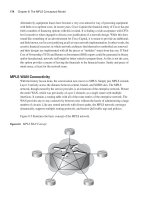
to be included at some point. Figure 2-2 illustrates the basic connectivity of the teleworker
solution.
The requirement for home office components includes the access methodology, remote VPN
router with QoS capabilities, and the desktop or laptop computer to be used by the teleworker.
Optionally, the components may include a Cisco IP Phone, Cisco Unified Video Advantage
(CUVA) camera for video, a wireless LAN access point (separate or integrated into the 800 series
router), and possibly a laptop docking station.
The corporate components include a VPN headend router, a multifunction security appliance
(such as the Cisco Adaptive Security Appliance [ASA]), management services, AAA services, and
devices capable of providing resilient termination of IPsec VPN tunnels.
In support of IP telephony components and services, there must be a call-control facility such as
Cisco Unified Communications Manager (formerly Cisco Unified CallManager [CUCM]) or
Cisco Unified Communications Manager Express (formerly Cisco Unified CallManager Express
[CME]). CME would be used only if the teleworker were connecting back to a smaller branch site
with its own local call-control functionality such as that seen in a distributed dial plan scenario.
Such services allow the teleworker IP Phone to be viewed as simply another extension of the
corporate telephone system. Just as any other extension on the network, the teleworker phone
would be able to use the PSTN connectivity of the central site and place or receive calls as if
located physically at the central site. Available services would include such capabilities as Unified
Messaging (UM) or basic Voice Messaging (VM) as well as the ability to log in as a call center
agent.
150x01x.book Page 43 Monday, June 18, 2007 8:52 AM
44 Chapter 2: Topologies for Teleworker Connectivity
Figure 2-2 Cisco Teleworker Components
Internet
V
IPSec VPN T
u
nnel
PSTN
Si Si
150x01x.book Page 44 Monday, June 18, 2007 8:52 AM
Challenges of Connecting Teleworkers 45
Traditional Teleworker versus Business-Ready Teleworker
So how does the business-ready teleworker differ from the teleworker or, in the traditional sense,
the telecommuter? The simplest answer is—evolution.
The telecommuter was simply connected however and whenever necessary. There was no thought
of “one experience regardless of device or locale.” There was no concept of SLA for the
teleworker. The ability for a full-time employee to perform all job functions from home was a
novelty rather than a compelling business case for cost reduction with increased productivity.
Every service offered to the telecommuter of yesterday was best-effort, if it could even be thought
of to that level. The construction of a corporate solution, security policy, and all-out elevation to
an actual executive-accepted business solution was beyond the extent of most lines of thought.
The advent of higher-speed broadband solutions available to residential areas is likely one of the
most significant drivers of the solution as well as one of the most relevant contributors to the
viability of the teleworker solution of today. With legacy dialup services, the connectivity was a
challenge. Providing the services and applications or necessary infrastructure to make a remotely
connected user feel as though they were sitting in the office was totally out of the question.
Fortunately, advances in security technologies, remote management, and control utilities have
greatly enhanced the viability of the teleworker solution.
Essentially, it comes down to the fact that the network was simply not ready to handle such
challenges as those presented by remotely connected offices and users. That is, until now. With the
teleworker architecture, applications and services can be delivered to home-based users, providing
a network experience similar to that of corporate office-based users.
150x01x.book Page 45 Monday, June 18, 2007 8:52 AM
46 Chapter 2: Topologies for Teleworker Connectivity
Foundation Summary
SONA provides the pathway to the Intelligent Information Network. The teleworker architecture
is a key part of the SONA framework at the networked infrastructure layer. Technologies have
been evolving over the past decade to allow for integrated services and applications to be provided
to the teleworker in a manner not previously possible.
Connection speeds and technologies available to the home office provide much needed bandwidth,
security, and services that enable one network experience regardless of locale. The “Business-
Ready Teleworker” SRND provides detailed guidance on the deployment of these technologies.
Table 2-2 lists connection types and bandwidths typically available (bandwidth speeds are typical
offerings, not minimum and maximum limits of the respective technology).
Once the access methodology is in place, the access options to be provided to teleworkers must be
decided upon. Table 2-3 lists typical options.
With the connection access methodology and options in place, QoS-protected services and
applications can be offered to teleworkers in a secure and robust manner.
Table 2-2 Remote Connectivity Access Methodologies
Technology
Upstream
Bandwidth
Downstream
Bandwidth Availability
DSL 256 to 1024 kbps 1.5 to 6 Mbps Nearly every local telephone provider
offers service
Cable 2 to 6 Mbps 4 to 6 Mbps Offered by cable TV providers who are
promising speeds of 25 Mbps to 100+
Mbps in the not-so-distant future
Fiber optic 2 to 5 Mbps 5 to 30 Mbps Limited offering by select providers
Table 2-3 Remote Connectivity Options
Technology Connection Type Connection Device
Remote-access
VPN
On-demand using a VPN client Laptop or desktop computer connection via
software VPN client
IPsec VPN Always-on or nailed-up VPN
connection
Remote router connection to VPN
Concentrator
150x01x.book Page 46 Monday, June 18, 2007 8:52 AM
Q&A 47
Q&A
The questions and scenarios in this book are designed to be challenging and to make sure that you
know the answer. Rather than allowing you to derive the answers from clues hidden inside the
questions themselves, the questions challenge your understanding and recall of the subject.
Hopefully, mastering these questions will help you limit the number of exam questions on which
you narrow your choices to two options, and then guess.
You can find the answers to these questions in Appendix A. For more practice with exam-like
question formats, use the exam engine on the CD-ROM.
1. Consider teleworker access options as discussed in the chapter. Compare IPsec VPN
connections with remote-access VPN connections and illustrate a viable case for each.
2. Consider a typical network implementation. List some tasks that must be completed and
components that must be acquired to support a business-ready teleworker environment.
3. Among the remote-connection topologies discussed in this chapter, describe a viable solution
or need that can be served by each. Those discussed include MPLS, Frame Relay/ATM, and
site-to-site VPN.
4. List at least three technologies that have evolved to a degree that has made it possible for the
teleworker of the 1990s to become the teleworker of today.
5. What are some risks associated with teleworker deployments?
6. How might some of the risks brought about by teleworker access be mitigated?
7. Among the solutions discussed in the chapter for teleworker connectivity are DSL, cable, and
fiber. Obviously, these do not encompass all the possible connection options for the
teleworker. What are some other possibilities?
8. Where is the best source of information and case studies for teleworker solutions
documentation?
150x01x.book Page 47 Monday, June 18, 2007 8:52 AM
Exam Topic List
This chapter covers the following topics that you
need to master for the CCNP ISCW exam:
■ Cable Access Technologies—Defines basic
terminology and standards relevant to cable
technology, the components of a cable system
that provide data services, and features of
cable technology
■ Radio Frequency Signals—Describes
digital cable use of radio frequency bands for
signal transmission
■ Data over Cable—Describes how data over
cable services can be delivered using an HFC
architecture
■ Cable Technology Issues—Describes the
combination of technologies necessary for
cable systems to function
■ Provisioning Cable Modems—Describes
the cable provisioning process in a customer
network
150x01x.book Page 48 Monday, June 18, 2007 8:52 AM
C H A P T E R
3
Using Cable to Connect
to a Central Site
Chapter 2, “Topologies for Teleworker Connectivity,” discussed some of the options available
for teleworker connectivity. Among these options is cable modem access. Heavy competition
has been building in recent years among cable providers and telephone companies in the
broadband services market. The companies offering these services are benefiting greatly from
both the Internet generation’s demand for high-speed access and the corporate move toward
teleworker deployments.
This chapter discusses, in more detail, the terminology, capabilities, and technologies
surrounding cable access as a teleworker access methodology.
“Do I Know This Already?” Quiz
The purpose of the “Do I Know This Already?” quiz is to help you decide whether you really
need to read the entire chapter. If you already intend to read the entire chapter, you do not
necessarily need to answer these questions now.
The 18-question quiz, derived from the major sections in the “Foundation Topics” portion of the
chapter, helps you to determine how to spend your limited study time.
Table 3-1 outlines the major topics discussed in this chapter and the “Do I Know This Already?”
quiz questions that correspond to those topics.
Table 3-1 “Do I Know This Already?” Foundation Topics Section-to-Question Mapping
Foundation Topics Section Questions Covered in This Section Score
Cable Access Technologies 1-8
Radio Frequency Signals 9-12
Data over Cable 13-16
Provisioning Cable Modems 17-18
Total Score
150x01x.book Page 49 Monday, June 18, 2007 8:52 AM
50 Chapter 3: Using Cable to Connect to a Central Site
1.
Which of the following would be found in a cable subscriber’s home?
a. Feeder network
b. Transportation network
c. Tap
d. Amplifier
2. Which of the following terms describes RF signals transmitted from the headend to the
subscriber?
a. Upstream
b. Downstream
c. HFC
d. CATV
3. Which of the following terms refers to a mixture of coaxial and fiber optic cable in the
network?
a. HFC
b. COAX
c. DOCSIS
d. NTSC
4. Which of the following cable components would provide signal processing, formatting, and
distribution?
a. Antenna site
b. Headend
c. Transportation network
d. Distribution network
e. Subscriber drop
CAUTION The goal of self-assessment is to gauge your mastery of the topics in this chapter.
If you do not know the answer to a question or are only partially sure of the answer, you should
mark this question wrong for purposes of self-assessment. Giving yourself credit for an answer
that you correctly guess skews your self-assessment results and might provide you with a false
sense of security.
150x01x.book Page 50 Monday, June 18, 2007 8:52 AM
“Do I Know This Already?” Quiz 51
5.
The cable modem connects to the cable system network via which of the following
components?
a. Antenna site
b. Headend
c. Transportation network
d. Distribution network
e. Subscriber drop
6. Remote antenna sites are connected to the headend via which of the following cable
components?
a. Antenna site
b. Headend
c. Transportation network
d. Distribution network
e. Subscriber drop
7. A coaxial cable contains all but which of the following components?
a. Copper conductor
b. Foil shielding
c. Braided wire shielding
d. Optical core
8. Cable systems came about to solve which of the following problems?
a. Poor-quality over-the-air transmissions
b. RF bandwidth competition
c. CATV regulations
d. FCC mandate
9. Which of the following is the RF range of the electromagnetic spectrum?
a. 1 MHz to 5 MHz
b. 10 GHz to 50 GHz
c. 5 MHz to 1 GHz
d. 500 kHz to 1 MHz
150x01x.book Page 51 Monday, June 18, 2007 8:52 AM
52 Chapter 3: Using Cable to Connect to a Central Site
10.
Specifications for data service over cable are defined by which of the following?
a. DOCSIS
b. NTSC
c. PAL
d. SECAM
11. The definition of data signals to be used by cable operators is a function of which of the
following OSI layers?
a. Layer 1
b. Layer 2
c. Layer 3
d. Layer 4
12. Which version of the DOCSIS document defines the use of channel bonding in cable
networks?
a. DOCSIS 1.0
b. DOCSIS 1.1
c. DOCSIS 2.0
d. DOCSIS 3.0
13. Which of the following are driving forces behind the advent of HFC networks?
a. Reduced signal degradation
b. Invulnerability to outside electromagnetic interference
c. Reduced service outages
d. RF range density on fiber
14. Upon reaching the subscriber home, the signal strength must be at what minimum level to
provide the necessary services?
a. 50 dB
b. 125 MHz
c. 6 MHz
d. 75 dB
150x01x.book Page 52 Monday, June 18, 2007 8:52 AM
“Do I Know This Already?” Quiz 53
15.
The CMTS resides where in the cable system network infrastructure?
a. Transportation network
b. Headend
c. Subscriber drop
d. Feeder trunks
16. In the subscriber home, which device takes the received signal and passes it on to individual
devices?
a. Tap
b. Splitter
c. Television
d. CM
17. During which step of the provisioning process does the CM find the pathway for data signals
received from the headend?
a. Upstream setup
b. Downstream setup
c. Layer 1 and 2 establishment
d. DOCSIS configuration
18. The DOCSIS configuration file is provided to the CM from which of the following devices?
a. DHCP server
b. Headend
c. TFTP server
d. ToD server
The answers to the “Do I Know This Already?” quiz are found in Appendix A, “Answers to the
‘Do I Know This Already?’ Quizzes and Q&A Sections.” The suggested choices for your next step
are as follows:
■ 12 or fewer overall score—Read the entire chapter. This includes the “Foundation Topics,”
“Foundation Summary,” and “Q&A” sections.
■ 14 or 15 overall score—Begin with the “Foundation Summary” section, and then go to the
“Q&A” section.
■ 16 or more overall score—If you want more review on these topics, skip to the “Foundation
Summary” section and then go to the “Q&A” section. Otherwise, move to the next chapter.
150x01x.book Page 53 Monday, June 18, 2007 8:52 AM
54 Chapter 3: Using Cable to Connect to a Central Site
Foundation Topics
Cable Access Technologies
Cable access is among the fastest growing technologies for home access to multiple services via
a common connection. One connection to the cable company carries the television signal and
Internet traffic. Most cable carriers are now getting into the voice market as well by providing
voice services with unlimited long distance and other traditional services over the cable
connection. The addition of teleworker functionality is a natural extension of this already
multiservice connection technology.
Today, cable access is typically sold in bundles. These bundles offer a mix of services including
television, Internet access, and voice. Most companies also offer a “build your own” bundle for
services, to allow a customer to mix and match the solution to meet their needs.
Cable Internet access typically is available at speeds ranging from 2-Mbps to 6-Mbps downstream
bandwidth (that is, from the Internet to the home) from the average carrier. The cost of this
connection is typically bundled with the monthly cable television recurring charge at a discounted
rate, as most companies seem to avoid offering Internet access without other services in the
bundle, most importantly, television. The concern with downstream speeds versus upstream
speeds is relevant simply because the bulk of the traffic load on the connection will be generated
by small outbound (from the subscriber) requests returning large amounts of inbound (to the
subscriber) data. For example, when a web browser is pointed to , little in
the way of traffic is generated by the request. However, a significant amount of information is
generated by the reply and subsequent loading of images and information requested. For this
reason, service providers have taken an asynchronous view of bandwidth allocation, preferring to
focus on the speed of the connection toward the subscriber.
Cable Technology Terminology
In any discussion of relatively new or different technologies, a definition of terminology
associated with that technology is necessary. This allows a more rapid familiarization with the
technology. With cable access, the new terms are quite numerous compared with other networking
technologies. The following are terms that will be referenced throughout this chapter:
■ Broadband—Data transmission using a multiplexing methodology to provide more efficient
use of available bandwidth. In cable, the term broadband refers to the frequency-division
multiplexing (FDM) of multiple signals in a wide radio frequency (RF) bandwidth over a
150x01x.book Page 54 Monday, June 18, 2007 8:52 AM
Cable Access Technologies 55
hybrid fiber-coaxial (HFC) network and the capability to handle large amounts of
information. FDM is a means by which information from multiple channels or frequencies
can be allocated bandwidth on a single wire.
■ Community Antenna Television (CATV)—A broad term referring to cable television in
general.
■ Coaxial cable—The primary medium used in the construction of cable television systems.
Coaxial cable (or coax) is used in the transmission of RF signals and has specific physical
characteristics regarding signal attenuation. These characteristics include cable diameter,
dielectric construction, ambient temperature, and operating frequency.
■ Tap—A device used to divide the input signal RF power to support multiple outlets.
Typically, cable operators deploy taps with two, four, or eight ports.
■ Amplifier—A device that magnifies an input signal, thus producing a significantly larger
output signal.
■ Hybrid fiber-coaxial (HFC)—A mixed optical-coaxial network in which fiber optic cable is
installed in place of some or all of the traditional trunk portion of the cable network.
■ Downstream—An RF signal transmission traveling in the direction of the subscriber from
the headend. Downstream is also called a forward path (viewed from the perspective of the
cable provider).
■ Upstream—An RF signal transmission traveling in the direction of the headend from the
subscriber. Upstream is also called a return or reverse path (again, from the provider
perspective).
As most of the general population has lived with cable television for a number of years, the coaxial
cable associated with it is quite readily recognized. Obviously, there are many types of coaxial
cable available in the marketplace at any given time. Each has differing characteristics and is
utilized in a variety of manners and technologies. For example, Ethernet 10BASE2 and 10BASE5
networks used a coaxial cable but each had differing physical and electrical characteristics. Table
3-2 shows the physical differences in some coaxial cable types.
Table 3-2 Coaxial Cable Types and Characteristics
Specification Cable Type American Wire Gauge (AWG)
10BASE2 Ethernet RG-58 20
10BASE5 Ethernet RG-11 12
CATV cable RG-6 or RG-59 18
150x01x.book Page 55 Monday, June 18, 2007 8:52 AM
56 Chapter 3: Using Cable to Connect to a Central Site
Hopefully, the table establishes something of a point of reference for coaxial cable uses. CATV
cable is somewhat thick and rigid in comparison to 10BASE2 or Thinnet cable. The 10BASE2
cable is quite flexible and, as the name “Thinnet” implies, quite small in diameter. In general, the
thinner the cable, the shorter the functional distance. The use of an HFC network remedies much
of the issue caused by cable distance limitations by introducing fiber optic cabling where needed.
Cable System Standards
Like any networking technology, cable systems have associated standards meant to loosely govern
the manner in which the technologies evolve and the manner in which they are implemented by
various hardware and software vendors. These standards include
■ National Television Standards Committee (NTSC)—Created in 1941, and named after its
authoring committee, NTSC defines technical standards for analog television systems
(utilizing a 6-MHz modulated signal) used in North America.
■ Phase Alternating Line (PAL)—A color coding system used in broadcast television
throughout Europe, Asia, Africa, Australia, Brazil, and Argentina using a 6-, 7-, or 8-MHz
modulated signal. Color differences signal an alternate phase at the horizontal line rate.
■ Système Electronic Couleur avec Memoire (SECAM)—An analog color television system
used in France and some other Eastern European countries using an 8-MHz modulated signal.
Modulation is the addition of information to an electronic or optical signal carrier. It can be applied to
direct current (DC) by turning it on or off, to alternating current (AC), or to optical signals. Signal
modulation is a process of varying a waveform to convey a message. The waveform can be changed
in amplitude, frequency, phase, or some combination of any or all three to convey these messages.
Cable System Components
The description of the components associated with cable systems essentially equates to defining
additional terminology. Typical components include:
■ Antenna site—A location containing a cable provider’s main receiving and satellite dish
facilities. This site is chosen based on potential for optimal reception of transmissions over
the air, via satellite, and via point-to-point communication.
■ Headend—A master facility where signals are received, processed, formatted, and
distributed over to the cable network. This includes both the transportation and distribution
networks. This facility is typically heavily secured and sometimes “lights-out,” meaning that
it is not regularly staffed.
■ Transportation network—The means and media by which remote antenna sites are connected
to the headend facility. Alternately, this could be a headend facility connection to the distribution
network. The transmission media may be microwave, coaxial supertrunk, or fiber optic.
150x01x.book Page 56 Monday, June 18, 2007 8:52 AM
Cable Access Technologies 57
■ Distribution network—In typical cable system architectures, consists of trunk and feeder
cables. The trunk is the backbone cable (usually 0.75-inch diameter) over which the primary
connectivity is maintained. In many networks, the distribution network tends to be a hybrid
fiber-coaxial network.
■ Node—Performs optical-to-RF conversion of CATV signal as needed. Feeder cables
(typically 0.5-inch diameter) originate from nodes that branch off into individual
communities to provide services to anywhere between 100 and 2000 customers each.
■ Subscriber drop—Connects the subscriber to the cable service network via a connection
between the feeder portion of a distribution network and the subscriber terminal device (for
example, TV set, VCR, high-definition TV set-top box, or cable modem). The subscriber drop
components consist of the physical coaxial cabling, grounding and attachment hardware,
passive devices, and a set-top box.
These components tend to be relatively easy to understand in concept. In practice, these are
implemented in differing manners depending on the cable provider. Regardless of the chosen
architecture, the concepts remain the same. Figure 3-1 illustrates typical cable provider
architecture.
Figure 3-1 Cable System Provider Architecture
Amplifier
Amplifier
Node
Distribution
Network
Distribution
Network
Traditional Coaxial Network
Hybrid Fiber-Coaxial Network
Node
Node
Feeder
Cables
Transportation
Network
Subscriber Drop
Headend
Antenna
Site
150x01x.book Page 57 Monday, June 18, 2007 8:52 AM
58 Chapter 3: Using Cable to Connect to a Central Site
Cable Features
Cable systems use coaxial cable at the subscriber premises. The cable itself consists of a copper
core surrounded by insulation and grounded shielding of braided wire. Figure 3-2 illustrates the
basic anatomy of the coaxial cable.
Figure 3-2 Coaxial Cable Anatomy
Traditional television signal transmitted over the air lacked in quality and was subject to
significant adverse effects from outside interference. It also required an external antenna in many
rural and suburban locations. In locations in or near a major city, “rabbit ears” were sufficient to
receive the transmissions. To overcome the need for external antennas, a coaxial cable was put in
place and connected directly into the television. Today, all televisions include a “cable-ready”
connection.
The construction of the cable is meant to minimize the effects of external electrical and RF
interference. The ground shielding and the signal wire share a common axis to provide better
protection against outside interference. The name “coaxial” is derived from this concept. This
allows a high-quality signal to be transmitted and protected until it arrives at the subscriber
premises. Initially, CATV networks were unidirectional and consisted of various amplifiers in
cascade compensating for the signal loss of the coaxial cable in series. Taps coupled video signal
from the main trunks to subscriber homes via drop cables. This is illustrated in Figure 3-1 as the
Traditional Coaxial Network. Today’s cable architecture is more in line with the right side of
Figure 3-1 with the advent of the HFC network. The previously unidirectional nature of cable
networks was a hindrance. The demand for bidirectional signals for both TV and the newer data
services drove the evolutionary cycle of the cable network to include fiber for longer reach without
the need for amplifiers.
The CATV system transmits RF signals from the headend via the trunk to a neighborhood node
and down into the distribution network to subscriber drops.
Outer Insulation
Foil Shielding
Conductor
Braided Wire Mesh Shielding
Insulation
150x01x.book Page 58 Monday, June 18, 2007 8:52 AM
Radio Frequency Signals 59
Cable System Benefits
The essential idea behind cable is to bring cost-effective television and services to a dense
subscriber base while maintaining high-quality content. Traditionally, this content was limited
simply to television channels ranging from “life-line” (local weather/news/information channels)
to premium-channel content.
In recent years, additional services have been added to the mix, including voice, data, and digital
television options. Over the next few years, all of the services offered by cable providers will
leverage the IP network as a platform for integrated services. IP-based services will carry all data,
voice, and video content to the subscriber premises. Set-top boxes currently using RF signal will
be IP attached and capable of delivering content to any number of access devices, including IP
phones, mobile phones, and more.
The more advanced capabilities offered by high-speed network access brought about a practice of
placing equipment, including telephone switches and cable modem termination systems (CMTS),
in a common facility so that services could be leveraged in a variety of manners. The resulting
broadband Internet access offering presents corporations with cost-effective connectivity for
teleworkers who connect back to a central site either through a IPsec VPN or remote-access VPN.
Additionally, interactive television content and Public Switched Telephone Network (PSTN) voice
access for voice and fax calls allow cable providers to offer VoIP services.
Radio Frequency Signals
The term radio frequency defines a relatively small portion of the known electromagnetic
spectrum. Figure 3-3 shows a small portion of the electromagnetic spectrum.
The whole of the electromagnetic spectrum is significantly more wide-ranging in terms of
frequencies than what is shown in the figure. Smaller still is the portion of the spectrum
specifically associated with RF (5 MHz to 1 GHz).
Generally, frequency is defined as the rate at which a repeated event occurs over time. In terms of
electromagnetism, that event is known as a cycle. One cycle per second is known as 1 hertz (Hz).
RF is measured in number of cycles or “waves” per second. Other characteristics of interest
include wavelength and amplitude. The wavelength is the distance between peaks or valleys in the
wave cycle (that is, the length of one complete cycle) where the amplitude is the peak height or
depth of the wave during the cycle. Frequency has an inverse relationship to wavelength. As
frequency increases, the wavelength tends to decrease. Where f is frequency, c is the speed of light
(3 * 10
8
meters per second), and Λ is wavelength:
f = c/Λ
150x01x.book Page 59 Monday, June 18, 2007 8:52 AM
60 Chapter 3: Using Cable to Connect to a Central Site
Figure 3-3 Partial Electromagnetic Spectrum
This calculation assumes a waveform moving through a vacuum. As the wave travels through
different media types, the frequency is constant but the wavelength and speed change. The effect
of various media types on a waveform is measured by a refractive index and would need to be
factored into the discussion for a true representation. However, because the physics of waveform
dynamics is outside the scope of the exam, further discussion will be put aside.
When tuning a radio or television, the tuner is finding individual frequencies in their respective
ranges. When a frequency used by a radio station is tuned in, the transmission from that station is
transformed into voltage that applies current of varying strength to a strong magnet in the speaker.
The speaker’s magnet becomes stronger with the application of that current. Metallic rings in the
diaphragm of the speaker are attracted to the magnet, creating motion and vibration that our ears
end up interpreting as sound.
In cable systems, a similar concept is applied. Rather than being transmitted over the air, the
signals are sent across the cable provider’s HFC to the subscriber. Televisions (high-definition or
10 m
10
8
10
9
10
11
10
12
10
13
10
14
10
15
10
16
1 m
10 cm
1 cm
1000 MHz
500 MHz
100 MHz
50 MHz
1 mm
1000 µm
100 µm
10 µm
1 µm
1000 nm
100 nm
10 nm
Ultraviolet
Visible
Infrared
Microwaves
Radio, TV
UHF
VHF
7–13
FM
VHF
2–6
Near IR
Far IR
Thermal IR
Radar
10
7
10
10
Frequency (Hz) Wavelength
150x01x.book Page 60 Monday, June 18, 2007 8:52 AM
Radio Frequency Signals 61
otherwise), set-top boxes, cable modems, and other equipment tune to various frequencies that
allow them to interpret the signals to provide content.
In terms of over-the-air television broadcasts, there are traditionally very high frequency (VHF)
and ultra-high frequency (UHF) channels. VHF utilizes the 30- to 300-MHz range and UHF the
300- to 3000-MHz range. The individual television channels utilize broadcast frequencies in their
respective ranges.
The cable television industry defines the television spectrum only in the downstream path. The
upstream path is not subject to a frequency plan. The frequencies can be monitored and upstream
signals placed into “clean” areas free from interference and noise from other signals. Typically the
range of 5 to 15 MHz tends to be noisy and difficult or impossible to utilize.
The cable network is able to transmit upstream and downstream simultaneously. For downstream
signals, those directed toward subscribers, the frequency range includes 50 to 860 MHz.
Alternately, upstream signals, those directed away from subscribers, utilize the range of 5 to 42
MHz.
The downstream range has been subdivided into smaller channels as defined by a standardized
frequency plan. This plan places a “guard band” between the ranges for upstream and downstream
transmissions. This is required due to the cutoff characteristics of high-pass and low-pass filters.
Such filters are needed to ensure that there is no signal leakage into other frequency spectrums.
Digital Signals over RF Channels
Cable specifications are defined by a document known as Data-over-Cable Service Interface
Specifications (DOCSIS). DOCSIS is an international standard developed by CableLabs, a
nonprofit organization and development consortium dedicated to cable-related technologies.
Founded in 1988, CableLabs is essentially charged with the testing and certification of cable
technology access equipment such as cable modems and CMTS. The organization makes
decisions on standardization and grants for DOCSIS certification and qualification.
The core of DOCSIS defines the manner in which individual components communicate in the
cable network. The specification for data-over-cable defines high-speed data transfer over an
existing CATV system. Cable operators use DOCSIS to implement Internet access over their
existing HFC infrastructure.
Cable transmissions are highly similar to wireless transmissions, with the obvious exception of the
presence or absence of copper. DOCSIS defines the frequency plan to be used as well (6 MHz for
DOCSIS, 7 MHz and 8 MHz for Euro-DOCSIS). As discussed, cable transmission uses the RF
bands. The RF band is composed of the frequencies above audio and below infrared.
150x01x.book Page 61 Monday, June 18, 2007 8:52 AM
62 Chapter 3: Using Cable to Connect to a Central Site
Within DOCSIS are the OSI Layer 1 and Layer 2 requirements for connectivity between cable
devices:
■ Physical layer (Layer 1)—Definition of data signals to be used by cable operators. DOCSIS
specifies bandwidths for each channel. These channel widths are 200 kHz, 400 kHz, 800 kHz,
1.6 MHz, 3.2 MHz, and 6.4 MHz. Additionally, DOCSIS defines the manner in which these
signals are modulated.
■ MAC layer (Layer 2)—Definition of a deterministic access method depending on DOCSIS
version: time division multiple access (TDMA) for version 1.0, 1.1, and 2.0 or synchronous
code division multiple access (S-CDMA) in version 2.0. The MAC layer protocol controls
access to the return path. The DOCSIS MAC protocol uses a request/grant system for
transmissions. This means that there is little or no use of contention for bandwidth as in
Ethernet networks (and no collisions).
Like many other standards and specifications relating to technology, DOCSIS is evolving.
DOCSIS version 1.0 was released in March 1997, followed by version 1.1 in April 1999. Version
2.0 came about in January 2002 as a result of increased demand for symmetric, real-time services
and applications such as IP telephony. This release enhanced the technology by augmenting
upstream speeds and putting QoS capabilities in place.
DOCSIS 3.0 was released in August 2006. Expected enhancements may include IPv6 support and
channel bonding. Channel bonding allows the use of multiple downstream and upstream channels
together, at the same time, by the same subscriber to increase overall bandwidth. In fact, through
the use of the Wideband architecture pioneered by Cisco, current expectations would allow the
offering of 100+ Mbps services to the subscriber. In fact, DOCSIS 3.0 expects capabilities
reaching 160 Mbps downstream with 120 Mbps upstream.
With new products on the horizon from Cisco’s Linksys and Scientific Atlanta business units,
speeds and services will most likely continue to evolve well beyond current imagination.
More information regarding DOCSIS can be found at CableLabs’ website: http://
www.cablemodem.com/specifications/.
Data over Cable
Television, alone, simply doesn’t meet the market demand anymore. Bruce Springsteen’s song,
“57 Channels (And Nothin’ On)” says it well. While in need of an update to a number of channels
placed well into triple-digits, it may well ring true for the foreseeable future. The Internet has
changed the definition of what is considered entertainment.
150x01x.book Page 62 Monday, June 18, 2007 8:52 AM