CCNP ONT Official Exam Certification Guide phần 2 pps
Bạn đang xem bản rút gọn của tài liệu. Xem và tải ngay bản đầy đủ của tài liệu tại đây (1.39 MB, 39 trang )
Digitizing and Packetizing Voice 19
While the call is in progress, the end points (R1 and R2 in this example) collect and analyze the
call statistics, such as packets sent and lost, and delay and jitter incurred (Theoretically, if the
quality of the call is unacceptable, the CA is notified, and the CA instructs both parties to terminate
the call.) If either phone hangs up, the gateway it is connected to (R1 or R2) notifies the CA of this
event. The CA instructs both parties that call termination procedures must be performed and call
resources must be released.
In the centralized call control model, the end points are not responsible for call control functions;
therefore, they are simpler devices to build, configure, and maintain. On the other hand, the CA is
a critical component within the centralized model and, to avoid a single point of failure, it requires
deployment of fault-tolerance technologies. It is easier to manage a centralized model than to
manage the distributed model, because only the CAs need to be configured and maintained.
Implementing new services, features, and policies is also easier in the centralized model.
Digitizing and Packetizing Voice
Upon completion of this section, you will be able to identify the steps involved in converting an
analog voice signal to a digital voice signal, explain the Nyquist theorem, the reason for taking
8000 voice samples per second; and explain the method for quantization of voice samples.
Furthermore, you will be familiar with standard voice compression algorithms, their bandwidth
requirements, and the quality of the results they yield. Knowing the purpose of DSP in voice
gateways is the last objective of this section.
Basic Voice Encoding: Converting Analog to Digital
Converting analog voice signal to digital format and transmitting it over digital facilities (such as
T1/E1) had been created and put into use before Bell (a North American telco) invented VoIP
technology in 1950s. If you use digital PBX phones in your office, you must realize that one of the
first actions that these phones perform is converting the analog voice signal to a digital format.
When you use your regular analog phone at home, the phone sends analog voice signal to the telco
CO. The Telco CO converts the analog voice signal to digital format and transmits it over the
public switched telephone network (PSTN). If you connect an analog phone to the FXS interface
of a router, the phone sends an analog voice signal to the router, and the router converts the analog
signal to a digital format. Voice interface cards (VIC) require DSPs, which convert analog voice
signals to digital signals, and vice versa.
Analog-to-digital conversion involves four major steps:
1. Sampling
2. Quantization
3. Encoding
4. Compression (optional)
1763fm.book Page 19 Monday, April 23, 2007 8:58 AM
20 Chapter 1: Cisco VoIP Implementations
Sampling is the process of periodic capturing and recording of voice. The result of sampling is
called a pulse amplitude modulation (PAM) signal. Quantization is the process of assigning
numeric values to the amplitude (height or voltage) of each of the samples on the PAM signal
using a scaling methodology. Encoding is the process of representing the quantization result for
each PAM sample in binary format. For example, each sample can be expressed using an 8-bit
binary number, which can have 256 possible values.
One common method of converting analog voice signal to digital voice signal is pulse code
modulation (PCM), which is based on taking 8000 samples per second and encoding each sample
with an 8-bit binary number. PCM, therefore, generates 64,000 bits per second (64 Kbps); it does
not perform compression. Each basic digital channel that is dedicated to transmitting a voice call
within PSTN (DS0) has a 64-kbps capacity, which is ideal for transmitting a PCM signal.
Compression, the last step in converting an analog voice signal to digital, is optional. The purpose
of compression is to reduce the number of bits (digitized voice) that must be transmitted per
second with the least possible amount of voice-quality degradation. Depending on the
compression standard used, the number of bits per second that is produced after the compression
algorithm is applied varies, but it is definitely less than 64 Kbps.
Basic Voice Encoding: Converting Digital to Analog
When a switch or router that has an analog device such as a telephone, fax, or modem connected
to it receives a digital voice signal, it must convert the analog signal to digital or VoIP before
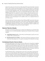
transmitting it to the other device. Figure 1-5 shows that router R1 receives an analog signal and
converts it to digital, encapsulates the digital voice signal in IP packets, and sends the packets to
router R2. On R2, the digital voice signal must be de-encapsulated from the received packets.
Next, the switch or router must convert the digital voice signal back to analog voice signal and
send it out of the FXS port where the phone is connected.
Figure 1-5 Converting Analog Signal to Digital and Digital Signal to Analog
1. Sampling
2. Quantization
3. Encoding
4. Compression
FXS
FXS
FXS
Analog Signal
1. Decompression
2. Decoding
3. Filtering and
Reconstructing the
Analog Signal
Digital Signal
VV
R1
Phone 1
IP Network
Digital Signal
R2
Analog Signal
Phone 2
IP PacketIP Packet
Encapsulation
De-Encapsulation
1763fm.book Page 20 Monday, April 23, 2007 8:58 AM
Digitizing and Packetizing Voice 21
Converting digital signal back to analog signal involves the following steps:
1. Decompression (optional)
2. Decoding and filtering
3. Reconstructing the analog signal
If the digitally transmitted voice signal was compressed at the source, at the receiving end, the
signal must first be decompressed. After decompression, the received binary expressions are
decoded back to numbers, which regenerate the PAM signal. Finally, a filtering mechanism
attempts to remove some of the noise that the digitization and compression might have introduced
and regenerates an analog signal from the PAM signal. The regenerated analog signal is hopefully
very similar to the analog signal that the speaker at the sending end had produced. Do not forget
that DPS perform digital-to-analog conversion, similar to analog to digital conversion.
The Nyquist Theorem
The number of samples taken per second during the sampling stage, also called the sampling rate,
has a significant impact on the quality of digitized signal. The higher the sampling rate is, the
better quality it yields; however, a higher sampling rate also generates higher bits per second that
must be transmitted. Based on the Nyquist theorem, a signal that is sampled at a rate at least twice
the highest frequency of that signal yields enough samples for accurate reconstruction of the signal
at the receiving end.
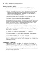
Figure 1-6 shows the same analog signal on the left side (top and bottom) but with two sampling
rates applied: the bottom sampling rate is twice as much as the top sampling rate. On the right side
of Figure 1-6, the samples received must be used to reconstruct the original analog signal. As you
can see, with twice as many samples received on the bottom-right side as those received on the
top-right side, a more accurate reconstruction of the original analog signal is possible.
Human speech has a frequency range of 200 to 9000 Hz. Hz stands for Hertz, which specifies the
number of cycles per second in a waveform signal. The human ear can sense sounds within a
frequency range of 20 to 20,000 Hz. Telephone lines were designed to transmit analog signals
within the frequency range of 300 to 3400 Hz. The top and bottom frequency levels produced by
a human speaker cannot be transmitted over a phone line. However, the frequencies that are
transmitted allow the human on the receiving end to recognize the speaker and sense his/her tone
of voice and inflection. Nyquist proposed that the sampling rate must be twice as much as the
highest frequency of the signal to be digitized. At 4000 Hz, which is higher than 3400 Hz (the
maximum frequency that a phone line was designed to transmit), based on the Nyquist theorem,
the required sampling rate is 8000 samples per second.
1763fm.book Page 21 Monday, April 23, 2007 8:58 AM
22 Chapter 1: Cisco VoIP Implementations
Figure 1-6 Effect of Higher Sampling Rate
Quantization
Quantization is the process of assigning numeric values to the amplitude (height or voltage) of
each of the samples on the PAM signal using a scaling methodology. A common scaling method
is made of eight major divisions called segments on each polarity (positive and negative) side.
Each segment is subdivided into 16 steps. As a result, 256 discrete steps (2 × 8 × 16) are possible.
The 256 steps in the quantization scale are encoded using 8-bit binary numbers. From the 8 bits,
1 bit represents polarity (+ or –), 3 represent segment number (1 through 8), and 4 bits represent
the step number within the segment (1 through 16). At a sampling rate of 8000 samples per second,
if each sample is represented using an 8-bit binary number, 64,000 bits per second are generated
for an analog voice signal. It must now be clear to you why traditional circuit-switched telephone
networks dedicated 64 Kbps channels, also called DS0s (Digital Signal Level 0), to each telephone
call.
Because the samples from PAM do not always match one of the discrete values defined by
quantization scaling, the process of sampling and quantization involves some rounding. This
rounding creates a difference between the original signal and the signal that will ultimately be
reproduced at the receiver end; this difference is called quantization error. Quantization error or
quantization noise, is one of the sources of noise or distortion imposed on digitally transmitted
voice signals.
1763fm.book Page 22 Monday, April 23, 2007 8:58 AM
Digitizing and Packetizing Voice 23
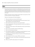
Figure 1-7 shows two scaling models for quantization. If you look at the graph on the top, you will
notice that the spaces between the segments of that graph are equal. However, the spaces between
the segments on the bottom graph are not equal: the segments closer to the x-axis are closer to each
other than the segments that are further away from the x-axis. Linear quantization uses graphs with
segments evenly spread, whereas logarithmic quantization uses graphs that have unevenly spread
segments. Logarithmic quantization yields smaller signal-to-noise quantization ratio (SQR),
because it encounters less rounding (quantization) error on the samples (frequencies) that human
ears are more sensitive to (very high and very low frequencies).
Figure 1-7 Linear Quantization and Logarithmic Quantization
Two variations of logarithmic quantization exist: A-Law and µ-Law. Bell developed µ-Law
(pronounced me-you-law) and it is the method that is most common in North America and Japan.
ITU modified µ-Law and introduced A-Law, which is common in countries outside North America
(except Japan). When signals have to be exchanged between a µ-Law country and an A-Law
country in the PSTN, the µ-Law country must change its signaling to accommodate the A-Law
country.
X-axis
Y-axis
Linear Quantization
Equidistant Segments
X-axis
Y-axis
Logarithmic Quantization
Segments are
NOT
Equidistant
1763fm.book Page 23 Monday, April 23, 2007 8:58 AM
24 Chapter 1: Cisco VoIP Implementations
Compression Bandwidth Requirements and Their Comparative Qualities
Several ITU compression standards exist. Voice compression standards (algorithms) differ based
on the following factors:
■ Bandwidth requirement
■ Quality degradation they cause
■ Delay they introduce
■ CPU overhead due to their complexity
Several techniques have been invented for measuring the quality of the voice signal that has been
processed by different compression algorithms (codecs). One of the standard techniques for
measuring quality of voice codecs, which is also an ITU standard, is called mean opinion score
(MOS). MOS values, which are subjective and expressed by humans, range from 1 (worst) to 5
(perfect or equivalent to direct conversation). Table 1-3 displays some of the ITU standard codecs
and their corresponding bandwidth requirements and MOS values.
MOS is an ITU standard method of measuring voice quality based on the judgment of several
participants; therefore, it is a subjective method. Table 1-4 displays each of the MOS ratings along
with its corresponding interpretation, and a description for its distortion level. It is noteworthy that
an MOS of 4.0 is deemed to be Toll Quality.
Table 1-3 Codec Bandwidth Requirements and MOS Values
Codec
Standard
Associated
Acronym Codec Name
Bit Rate
(BW)
Quality Based on
MOS
G.711 PCM Pulse Code Modulation 64 Kbps 4.10
G.726 ADPCM Adaptive Differential PCM 32, 24,
16 Kbps
3.85 (for 32 Kbps)
G.728 LDCELP Low Delay Code Exited
Linear Prediction
16 Kbps 3.61
G.729 CS-ACELP Conjugate Structure
Algebraic CELP
8 Kbps 3.92
G.729A CS-ACELP
Annex a
Conjugate Structure
Algebraic CELP Annex A
8 Kbps 3.90
1763fm.book Page 24 Monday, April 23, 2007 8:58 AM
Digitizing and Packetizing Voice 25
Perceptual speech quality measurement (PSQM), ITU’s P.861 standard, is another voice quality
measurement technique implemented in test equipment systems offered by many vendors. PSQM
is based on comparing the original input voice signal at the sending end to the transmitted voice
signal at the receiving end and rating the quality of the codec using a 0 through 6.5 scale, where 0
is the best and 6.5 is the worst.
Perceptual analysis measurement system (PAMS) was developed in the late 1990s by British
Telecom. PAMS is a predictive voice quality measurement system. In other words, it can predict
subjective speech quality measurement methods such as MOS.
Perceptual evaluation of speech quality (PESQ), the ITU P.862 standard, is based on work done
by KPN Research in the Netherlands and British Telecommunications (developers of PAMS).
PESQ combines PSQM and PAMS. It is an objective measuring system that predicts the results of
subjective measurement systems such as MOS. Various vendors offer PESQ-based test equipment.
Digital Signal Processors
Voice-enabled devices such as voice gateways have special processors called DSPs. DSPs are
usually on packet voice DSP modules (PVDM). Certain voice-enabled devices such as voice
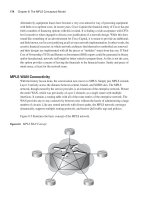
network modules (VNM) have special slots for plugging PVDMs into them. Figure 1-8 shows a
network module high density voice (NM-HDV) that has five slots for PVDMs. The NM in Figure
1-8 has four PVDMs plugged into it . Different types of PVDMs have different numbers of DSPs,
and each DSP handles a certain number of voice terminations. For example, one type of DSP can
handle tasks such as codec and transcoding for up to 16 voice channels if a low-complexity codec
is used, or up to 8 voice channels if a high-complexity codec is used.
Table 1-4 Mean Opinion Score
Rating Speech Quality Level of Distortion
5 Excellent Imperceptible
4 Good Just perceptible but not annoying
3Fair Perceptible but slightly annoying
2 Poor Annoying but not objectionable
1 Unsatisfactory Very annoying and objectionable
1763fm.book Page 25 Monday, April 23, 2007 8:58 AM
26 Chapter 1: Cisco VoIP Implementations
Figure 1-8 Network Module with PVDMs
DSPs provide three major services:
■ Voice termination
■ Transcoding
■ Conferencing
Calls to or from voice interfaces of a voice gateway are terminated by DSPs. DSP performs
analog-to-digital and digital-to-analog signal conversion. It also performs compression (codec),
echo cancellation, voice activity detection (VAD), comfort noise generation (CNG), jitter handling,
and some other functions.
When the two parties in an audio call use different codecs, a DSP resource is needed to perform
codec conversion; this is called transcoding. Figure 1-9 shows a company with a main branch and
a remote branch with an IP connection over WAN. The voice mail system is in the main branch,
and it uses the G.711 codec. However, the branch devices are configured to use G.729 for VoIP
communication with the main branch. In this case, the edge voice router at the main branch needs
to perform transcoding using its DSP resources so that the people in the remote branch can retrieve
their voice mail from the voice mail system at the main branch.
DSPs can act as a conference bridge: they can receive voice (audio) streams from the participants
of a conference, mix the streams, and send the mix back to the conference participants. If all the
conference participants use the same codec, it is called a single-mode conference, and the DSP
does not have to perform codec translation (called transcoding). If conference participants use
different codecs, the conference is called a mixed-mode conference, and the DSP must perform
transcoding. Because mixed-mode conferences are more complex, the number of simultaneous
mixed-mode conferences that a DSP can handle is less than the number of simultaneous single-
mode conferences it can support.
PVDM2 Slots
(Two on Each Side, Total of
Four)
Onboard T1/E1
–
Ports
1763fm.book Page 26 Monday, April 23, 2007 8:58 AM
Encapsulating Voice Packets 27
Figure 1-9 DSP Transcoding Example
Encapsulating Voice Packets
This section explains the protocols and processes involved in delivering VoIP packets as opposed
to delivering digitized voice over circuit-switched networks. It also explains the RTP as the
transport protocol of choice for voice and discusses the benefits of RTP header compression
(cRTP).
End-to-End Delivery of Voice
To review the traditional model of voice communication over the PSTN, imagine a residential
phone that connects to the telco CO switch using an analog telephone line. After the phone goes
off-hook and digits are dialed and sent to the CO switch, the CO switch, using a special signaling
protocol, finds and sends call setup signaling messages to the CO that connects to the line of the
destination number. The switches within the PSTN are connected using digital trunks such as
T1/E1 or T3/E3. If the call is successful, a single channel (DS0) from each of the trunks on the
path that connects the CO switches of the caller and called number is dedicated to this phone call.
Figure 1-10 shows a path from the calling party CO switch on the left to the called party CO switch
on the right.
Main Branch
Voice Mail Server
(G.711 Only)
G.711
Remote Branch
IP
IP WAN
(G.729 Only)
G.729
Transcoding
DSP
1763fm.book Page 27 Monday, April 23, 2007 8:58 AM
28 Chapter 1: Cisco VoIP Implementations
Figure 1-10 Voice Call over Traditional Circuit-Switched PSTN
After the path between the CO switches at each end is set up, while the call is active, analog voice
signals received from the analog lines must be converted to digital format, such as G.711 PCM,
and transmitted over the DS0 that is dedicated to this call. The digital signal received at each CO
must be converted back to analog before it is transmitted over the residential line. The bit trans-
mission over DS0 is a synchronous transmission with guaranteed bandwidth, low and constant
end-to-end delay, plus no chance for reordering. When the call is complete, all resources and the
DS0 channel that is dedicated to this call are released and are available to another call.
If two analog phones were to make a phone call over an IP network, they would each need to be
plugged into the FXS interface of a voice gateway. Figure 1-11 displays two such gateways (R1
and R2) connected over an IP network, each of which has an analog phone connected to its FXS
interface.
PSTN
Analog Residential
Phone
Analog Residential
Phone
Analog Residential Line
Digital
Tr unks
Analog-to-
Digital
Conversion
Vice Versa
Analog-to-
Digital
Conversion
Vice Versa
Digital
Tr unks
Analog
Residential
Line
CO
CO
1763fm.book Page 28 Monday, April 23, 2007 8:58 AM
Encapsulating Voice Packets 29
Figure 1-11 Voice Call over IP Networks
Assume that phone 1 on R1 goes off-hook and dials a number that R1 maps to R2. R1 will send a
VoIP signaling call setup message to R2. If the call is accepted and it is set up, each of R1 and R2
will have to do the following:
■ Convert the analog signal received from the phone on the FXS interface to digital (using a
codec such as G.711).
■ Encapsulate the digital voice signal into IP packets.
■ Route the IP packets toward the other router.
V
V
D
D
D
D
D
D
D
D
D
V
V
V
V
V
Analog
Phone 2
Analog
Phone 1
Analog
IP Network
FXS
FXS
Analog-to-
Digital
Conversion &
Vice Versa,
Plus VoIP
Encapsulation
and
De-Encapsulation
Analog-to-Digital
Conversion
& Vice Versa,
Plus VoIP
Encapsulation and
De-Encapsulation
R2
R1
LEGEND:
D
V
Data Over IP:
Voice Over IP:
1763fm.book Page 29 Monday, April 23, 2007 8:58 AM
30 Chapter 1: Cisco VoIP Implementations
■ De-encapsulate the digital voice from the received IP packets.
■ Convert the digital voice to analog and transmit it out of the FXS interface.
Notice that in this case, in contrast to a call made over the circuit-switched PSTN network, no end-
to-end dedicated path is built for the call. IP packets that encapsulate digitized voice (20 ms of
audio by default) are sent independently over the IP network and might arrive out of order and
experience different amounts of delay. (This is called jitter.) Because voice and data share the IP
network with no link or circuit dedicated to a specific flow or call, the number of data and voice
calls that can be active at each instance varies. Also, it affects the amount of congestion, loss, and
delay in the network.
Protocols Used in Voice Encapsulation
Even though the term VoIP implies that digitized voice is encapsulated in IP packets, other
protocol headers and mechanisms are involved in this process. Although the two major TCP/IP
transport layer protocols, namely TCP and UDP, have their own merits, neither of these protocols
alone is a suitable transport protocol for real-time voice. RTP, which runs over UDP using UDP
ports 16384 through 32767, offers a good transport layer solution for real-time voice and video.
Table 1-5 compares TCP, UDP, and RTP protocols with respect to reliability, sequence numbering
(re-ordering), time-stamping, and multiplexing.
TCP provides reliability by putting sequence numbers on the TCP segments sent and expecting
acknowledgements for the TCP segment numbers arriving at the receiver device. If a TCP segment
is not acknowledged before a retransmission timer expires, the TCP segment is resent. This model
is not suitable for real-time applications such as voice, because the resent voice arrives too late for
it to be useful. Therefore, reliability is not a necessary feature for a voice transport protocol. UDP
and RTP do not offer reliable transport. Please note, however, that if the infrastructure capacity,
configuration, and behavior are such that there are too many delayed or lost packets, the quality of
voice and other real-time applications will deteriorate and become unacceptable.
Data segmentation, sequence numbering, reordering, and reassembly of data are services that the
transport protocol must offer, if the application does not or cannot perform those tasks. The
Table 1-5 Comparing Suitability of TCP/IP Transport Protocols for Voice
Feature Required for Voice TCP Offers UDP Offers RTP Offers
Reliability No Yes No No
Sequence numbering
and reordering
Yes Yes No Yes
Time-stamping Yes No No Yes
Multiplexing Yes Yes Yes No
1763fm.book Page 30 Monday, April 23, 2007 8:58 AM
Encapsulating Voice Packets 31
protocol to transport voice must offer these services. TCP and RTP offer those services, but pure
UDP does not.
Voice or audio signal is released at a certain rate from its source. The receiver of the voice or
audio signal must receive it at the same rate that the source has released it; otherwise, it will sound
different or annoying, or it might even become incomprehensible. Putting timestamps on the
segments encapsulating voice, at source, enables the receiving end to release the voice at the same
rate that it was released at the source. RTP adds timestamps in the segments at source, but TCP
and UDP do not.
Both TCP and UDP allow multiple applications to simultaneously use their services to transport
application data, even if all the active flows and sessions originate and terminate on the same pair
of IP devices. The data from different applications is distinguished based on the TCP or UDP port
number that is assigned to the application while it is active. This capability of the TCP and UDP
protocols is called multiplexing. On the other hand, RTP flows are differentiated based on the
unique UDP port number that is assigned to each of the RTP flows. UDP numbers 16384 through
32767 are reserved for RTP. RTP does not have a multiplexing capability.
Knowing that RTP runs over UDP, considering the fact that neither UDP nor RTP offers the
unneeded reliability and overhead offered by TCP, and that RTP uses sequence numbers and time-
stamping, you can conclude that RTP is the best transport protocol for voice, video, and other real-
time applications. Please note that even though the reliability that TCP offers might not be useful
for voice applications, it is desirable for certain other applications.
RTP runs over UDP; therefore, a VoIP packet has IP (20 bytes), UDP (8 bytes), and RTP (12 bytes)
headers added to the encapsulated voice payload. DSPs usually make a package out of 10-ms
worth of analog voice, and two of those packages are usually transported within one IP packet. (A
total of 20-ms worth of voice in one IP packet is common.) The number of bytes resulting from
20 ms (2 × 10 ms) worth of analog voice directly depends on the codec used. For instance, G.711,
which generates 64 Kbps, produces 160 bytes from 20 ms of analog voice, whereas G.729, which
generates 8 Kbps, produces 20 bytes for 20 ms of analog voice signal. The RTP, UDP, and IP
headers, which total 40 bytes, are added to the voice bytes (160 bytes for G.711 and 20 bytes for
G.729) before the whole group is encapsulated in the Layer 2 frame and transmitted.
Figure 1-12 displays two VoIP packets. One packet is the result of the G.711 codec, and the other
is the result of the G.729 codec. Both have the RTP, UDP, and IP headers. The Layer 2 header is
not considered here. The total number of bytes resulting from IP, UDP, and RTP is 40. Compare
this 40-byte overhead to the size of the G.711 payload (160 bytes) and of the G.729 payload (20
bytes). The ratio of overhead to payload is 40/160, or 25 percent, when G.711 is used; however,
the overhead-to-payload ratio is 40/20, or 200 percent, when G.729 is used!
1763fm.book Page 31 Monday, April 23, 2007 8:58 AM
32 Chapter 1: Cisco VoIP Implementations
Figure 1-12 Voice Encapsulation Utilizing G.711 and G.729
If you ignore the Layer 2 overhead for a moment, just based on the overhead imposed by RTP,
UDP, and IP, you can recognize that the required bandwidth is more than the bandwidth that is
needed for the voice payload. For instance, when the G.711 codec is used, the required bandwidth
for voice only is 64 Kbps, but with 25 percent added overhead of IP, UDP, and RTP, the required
bandwidth increases to 80 Kbps. If G.729 is used, the bandwidth required for pure voice is only 8
Kbps, but with the added 200 percent overhead imposed by IP, UDP, and RTP, the required
bandwidth jumps to 24 Kbps. Again, note that the overhead imposed by the Layer 2 protocol and
any other technologies such as tunneling or security has not even been considered.
Reducing Header Overhead
An effective way of reducing the overhead imposed by IP, UDP, and RTP is Compressed RTP
(cRTP). cRTP is also called RTP header compression. Even though its name implies that cRTP
compresses the RTP header only, the cRTP technique actually significantly reduces the overhead
imposed by all IP, UDP, and RTP protocol headers. cRTP must be applied on both sides of a link,
and essentially the sender and receiver agree to a hash (number) that is associated with the 40 bytes
of IP, UDP, and TCP headers. Note that cRTP is applied on a link-by-link basis.
The premise of cRTP is that most of the fields in the IP, UDP, and RTP headers do not change
among the elements (packets) of a common packet flow. After the initial packet with all the
headers is submitted, the following packets that are part of the same packet flow do not carry the
40 bytes of headers. Instead, the packets carry the hash number that is associated with those 40
bytes (sequence number is built in the hash). The main difference among the headers of a packet
flow is the header checksum (UDP checksum). If cRTP does not use this checksum, the size of the
IP UDP RTP
20 ms of Digitized Voice Using G.711
20
Bytes
8
Bytes
12
Bytes
20
Bytes
8
Bytes
12
Bytes
160
Bytes
Digitized Voice
Digitized Voice
20 ms of Digitized Voice Using G.729
64000 bps ϫ 20/1000 sec ϫ 1 Byte/8 Bits
8000 bps ϫ 20/1000 sec ϫ 1 Byte/8 Bits
IP UDP RTP
20
Bytes
1763fm.book Page 32 Monday, April 23, 2007 8:58 AM
Encapsulating Voice Packets 33
overhead is reduced from 40 bytes to only 2 bytes. If the checksum is used, the 40 bytes overhead
is reduced to 4 bytes. If, during transmission of packets, a cRTP sender notices that a packet header
has changed from the normal pattern, the entire header instead of the hash is submitted.
Figure 1-13 displays two packets. The top packet has a 160-byte voice payload because of usage
of the G.711 codec, and a 2-byte cRTP header (without checksum). The cRTP overhead-to-voice
payload ratio in this case is 2/160, or 1.25 percent. Ignoring Layer 2 header overhead, because
G.711 requires 64 Kbps for the voice payload, the bandwidth needed for voice and the cRTP
overhead together would be 64.8 Kbps (without header checksum). The bottom packet has a
20-byte voice payload because of usage of the G.729 codec and a 2-byte cRTP header (without
checksum). The cRTP overhead-to-voice payload ratio in this case is 2/20, or 10 percent. Ignoring
Layer 2 header overhead, because G.729 requires 8 Kbps for the voice payload, the bandwidth
needed for voice and the cRTP overhead together would be 8.8 Kbps (without header checksum).
Figure 1-13 RTP Header Compression (cRTP)
The benefit of using cRTP with smaller payloads (such as digitized voice) is more noticeable than
it is for large payloads. Notice that with cRTP, the total bandwidth requirement (without Layer 2
overhead considered) dropped from 80 Kbps to 64.8 Kbps for G.711, and it dropped from 24 Kbps
to 8.8 Kbps for G.729. The relative gain is more noticeable for G.729. You must, however, consider
factors before enabling cRTP on a link:
■ cRTP does offer bandwidth saving, but it is only recommended for use on slow links (links
with less than 2 Mbps bandwidth). More accurately, Cisco recommends cRTP on 2 Mbps
links only if the cRTP is performed in hardware. cRTP is only recommended on the main
processor if the link speed is below 768 kbps.
cRTP
2 Bytes Without Checksum
4 Bytes With Checksum
Digitized Voice
160
Bytes
64000 bps ϫ 20/1000 sec ϫ 1 Byte/8 Bits
20 ms of Digitized Voice Using G.711
Digitized Voice
cRTP
2 Bytes Without Checksum
4 Bytes With Checksum
8000 bps ϫ 20/1000 sec ϫ 1 Byte/8 Bits
20
Bytes
20 ms of Digitized Voice Using G.729
1763fm.book Page 33 Monday, April 23, 2007 8:58 AM
34 Chapter 1: Cisco VoIP Implementations
■ cRTP has a processing overhead, so make sure the device where you enable cRTP has enough
resources.
■ The cRTP process introduces a delay due to the extra computations and header replacements.
■ You can limit the number of cRTP sessions on a link. By default, Cisco IOS allows up to only
16 concurrent cRTP sessions. If enough resources are available on a device, you can increase
this value.
Bandwidth Calculation
Computing the exact amount of bandwidth needed for each VoIP call is necessary for planning and
provisioning sufficient bandwidth in LANs and WANs. The previous section referenced parts of
this computation, but this section thoroughly covers the subject of VoIP bandwidth calculation.
The impact of packet size, Layer 2 overhead, tunneling, security, and voice activity detection are
considered in this discussion.
Impact of Voice Samples and Packet Size on Bandwidth
DSP coverts analog voice signal to digital voice signal using a particular codec. Based on the
codec used, the DSP generates so many bits per second. The bits that are generated for 10
milliseconds (ms) of analog voice signal form one digital voice sample. The size of the digital
voice sample depends on the codec used. Table 1-6 shows how the digital voice sample size
changes based on the codec used. The number of voice bytes for two digital voice samples using
different codecs is shown in the last column.
Table 1-6 Examples of Voice Payload Size Using Different Codecs
Codec:
Bandwidth
Size of Digital Voice Sample for
10 ms of Analog Voice in Bits
Size of 10 ms
Digitized Voice
in Bytes
Size of Two
Digital Voice
Samples (20 ms)
G.711: 64 Kbps 64,000 bps × 10/1000 sec = 640 bits 80 bytes 2 × 80 = 160 bytes
G.726 r32: 32 Kbps 32,000 bps
× 10/1000 sec = 320 bits 40 bytes 2 × 40 = 80 bytes
G.726 r24: 24 Kbps 24,000 bps
× 10/1000 sec = 240 bits 30 bytes 2 × 30 = 60 bytes
G.726 r16: 16 Kbps 16,000 bps
× 10/1000 sec = 160 bits 20 bytes 2 × 20 = 40 bytes
G.728: 16 Kbps 16,000 bps
× 10/1000 sec = 160 bits 20 bytes 2 × 20 = 40 bytes
G.729: 8 Kbps 8000 bps
× 10/1000 sec = 80 bits 10 bytes 2 × 10 = 20 bytes
1763fm.book Page 34 Monday, April 23, 2007 8:58 AM
Bandwidth Calculation 35
The total size of a Layer 2 frame encapsulating a VoIP packet depends on the following factors:
■ Packet rate and packetization size—Packet rate, specified in packets per seconds (pps), is
inversely proportional to packetization size, which is the amount of voice that is digitized and
encapsulated in each IP packet. Packetization size is expressed in bytes and depends on the
codec used and the amount of voice that is digitized. For example, if two 10-ms digitized
voice samples (total of 20 ms voice) are encapsulated in each IP packet, the packet rate will
be 1 over 0.020, or 50 packets per second (pps), and if G.711 is used, the packetization size
will be 160 bytes. (See Table 1-6.)
■ IP overhead—IP overhead refers to the total number of bytes in the RTP, UDP, and IP
headers. With no RTP header compression, the IP overhead is 40 bytes. If cRTP with no
header checksum is applied to a link, the IP overhead drops to 2 bytes, and with header
checksum, the IP header checksum is 4 bytes.
■ Data link overhead—Data link layer overhead is always present, but its size depends on the
type of encapsulation (frame type) and whether link compression applied. For instance, the
data link layer overhead of Ethernet is 18 bytes (it is 22 bytes with 802.1Q).
■ Tunneling overhead—Tunneling overhead is only present if some type of tunneling is used.
Generic routing encapsulation (GRE), Layer 2 Tunneling Protocol (L2TP), IP security
(IPsec), QinQ (802.1Q), and Multiprotocol Label Switching (MPLS) are common tunneling
techniques with their own usage reasons and benefits. Each tunneling approach adds a specific
number of overhead bytes to the frame.
Codecs are of various types. The size of each VoIP packet depends on the codec type used and the
number of voice samples encapsulated in each IP packet. The number of bits per second that each
codec generates is referred to as codec bandwidth. The following is a list of some ITU codec
standards, along with a brief description for each:
■ G.711 is PCM—Based on the 8000 samples per second rate and 8 bits per sample, PCM
generates 64,000 bits per second, or 64 Kbps. No compression is performed.
■ G.726 is adaptive differential pulse code modulation (ADPCM)—Instead of constantly
sending 8 bits per sample, fewer bits per sample, which only describe the change from the
previous sample, are sent. If the number of bits (that describe the change) sent is 4, 3, or 2,
G.726 generates 32 Kbps, 24 Kbps, or 16 Kbps respectively, and it is correspondingly called
G.726 r32, G.726 r24, or G.726 r16.
■ G.722 is wideband speech encoding standard—G.722 divides the input signal into two
subbands and encodes each subband using a modified version of ADPCM. G.722 supports a
bit rate of 64 Kbps, 56 Kbps, or 48 Kbps.
1763fm.book Page 35 Monday, April 23, 2007 8:58 AM
36 Chapter 1: Cisco VoIP Implementations
■ G.728 is low delay code exited linear prediction (LDCELP)—G.728 uses codes that
describe voice samples generated by human vocal cords, and it utilizes a prediction technique.
Wave shapes of five samples (equivalent of 40 bits in PCM) are expressed with 10-bit codes;
therefore, the G.728 bandwidth drops to 16 Kbps.
■ G.729 is conjugate structure algebraic code exited linear prediction (CS-ACELP)—
G.729 also uses codes from a code book; however, 10 samples (equivalent of 80 PCM bits)
are expressed with 10-bit codes. Therefore, the G.729 is only 8 Kbps.
DSPs produce one digital voice sample for 10 milliseconds (ms) of analog voice signal. It is
common among Cisco voice-enabled devices to put two digital voice samples in one IP packet,
but it is possible to put three or four samples in one IP packet if desired. The packetization period
is the amount of analog voice signal (expressed in milliseconds) that is encapsulated in each IP
packet (in digitized format). The merit of more voice samples in a packet—longer packetization
period, in other words—is reduction in the overhead-to-payload ratio.
The problem, though, with putting too many digital voice samples in one IP packet is that when a
packet is dropped, too much voice is lost. That loss has a more noticeable negative effect on the
quality of the call when packets are dropped. The other drawback of a longer packetization period
(more than two or three digital voice samples in one IP packet) is the extra packetization delay it
introduces. More voice bits means a larger IP packet, and a larger IP packet means a longer
packetization period.
Table 1-7 shows a few examples to demonstrate the combined effect of codec used and packet-
ization period (number of digitized 10-ms voice samples per packet) on the voice encapsulating
IP packet (VoIP) size and on the packet rate. The examples in Table 1-7 do not use compressed
RTP and make no reference to the effects of Layer 2 and tunneling overheads.
Table 1-7 Packet Size and Packet Rate Variation Examples
Codec and Packetization Period
(Number of Encapsulated
Digital Voice Samples)
Codec
Bandwidth
Voice Payload
(Packetization)
Size
IP
Overhead
Total IP
(VoIP)
Packet Size
Packet
Rate
(pps)
G.711 with 20-ms packetization
period (two 10-ms samples)
64 Kbps 160 bytes 40 bytes 200 bytes 50 pps
G.711 with 30-ms packetization
period (three 10-ms samples)
64 Kbps 240 bytes 40 bytes 280 bytes 33.33 pps
G.729 with 20 ms packetization
period (two 10-ms samples)
8 Kbps 20 bytes 40 bytes 60 bytes 50 pps
G.729 with 40 ms packetization
period (four 10-ms samples)
8 Kbps 40 bytes 40 bytes 80 bytes 25 pps
1763fm.book Page 36 Monday, April 23, 2007 8:58 AM
Bandwidth Calculation 37
Data Link Overhead
Transmitting an IP packet over a link requires encapsulation of the IP packet in a frame that is
appropriate for the data link layer protocol provisioned on that link. For instance, if the data link
layer protocol used on a link is PPP, the interface connected to that link must be configured for
PPP encapsulation. In other words, any packet to be transmitted out of that interface must be
encapsulated in a PPP frame. When a router routes a packet, the packet can enter the router via an
interface with a certain encapsulation type such as Ethernet, and it can leave the router through
another interface with a different encapsulation such as PPP. After the Ethernet frame enters the
router via the ingress interface, the IP packet is de-encapsulated. Next, the routing decision directs
the packet to the egress interface. The packet has to be encapsulated in the frame proper for the
egress interface data link protocol before it is transmitted.
Different data link layer protocols have a different number of bytes on the frame header; for VoIP
purposes, these are referred to as data link overhead bytes. Data link overhead bytes for Ethernet,
Frame Relay, Multilink PPP (MLP), and Dot1Q (802.1Q) are 18, 6, 6, and 22 bytes in that order,
to name a few. During calculation of the total bandwidth required for a VoIP call, for each link type
(data link layer protocol or encapsulation), you must consider the appropriate data link layer
overhead.
Security and Tunneling Overhead
IPsec is an IETF protocol suite for secure transmission of IP packets. IPsec can operate in two
modes: Transport mode or Tunnel mode. In Transport mode, encryption is applied only to the
payload of the IP packet, whereas in Tunnel mode, encryption is applied to the whole IP packet,
including the header. When the IP header is encrypted, the intermediate routers can no longer
analyze and route the IP packet. Therefore, in Tunnel mode, the encrypted IP packet must be
encapsulated in another IP packet, whose header is used for routing purposes. The new and extra
header added in Transport mode means 20 extra bytes in overhead. In both Transport mode and
Tunnel mode, either an Authentication Header (AH) or an Encapsulating Security Payload (ESP)
header is added to the IP header. AH provides authentication only, whereas ESP provides
authentication and encryption. As a result, ESP is used more often. AH, ESP, and the extra IP
header of the Tunnel mode are the IPsec overheads to consider during VoIP bandwidth calculation.
IPsec also adds extra delay to the packetization process at the sending and receiving ends.
Other common tunneling methods and protocols are not focused on security. IP packets or data
link layer frames can be tunneled over a variety of protocols; the following is a short list of
common tunneling protocols:
■ GRE—GRE transports Layer 3 (network layer) packets, such as IP packets, or Layer 2 (data
link) frames, over IP.
■ Layer 2 Forwarding (L2F) and L2TP—L2F and L2TP transport PPP frames over IP.
1763fm.book Page 37 Monday, April 23, 2007 8:58 AM
38 Chapter 1: Cisco VoIP Implementations
■ PPP over Ethernet (PPPoE)—PPPoE transports PPP frames over Ethernet frames.
■ 802.1Q tunneling (QinQ)—An 802.1Q frame with multiple 802.1Q headers is called QinQ.
Layer 2 switching engines forward the QinQ frame based on the VLAN number in the top
802.1Q header. When the top header is removed, forwarding of the frame based on the VLAN
number in the lower 802.1Q header begins.
Whether one of the preceding tunneling protocols, IPsec in Tunnel mode, or any other tunneling
protocol is used, the tunnel header is always present and is referred to as tunneling overhead. If
any tunneling protocol is used, the tunneling overhead must be considered in VoIP bandwidth
calculation. Table 1-8 shows the tunneling overhead—in other words, the tunnel header size—for
a variety of tunneling options.
If a company connects two of its sites over the public Internet using IPsec in Tunnel mode (also
called IPsec VPN), you must be able to calculate the total size of the IP packet encapsulating voice
(VoIP). To do that, you need to know the codec used, the packetization period, and whether
compressed RTP is used. The fictitious company under discussion uses the G.729 codec for site-
to-site IP Telephony and a 20-ms packetization period (two 10-ms equivalent digital voice samples
per packet); it does not utilize cRTP. For IPsec, assume tunnel mode with ESP header utilizing
3DES for encryption and SHA-1 for authentication. The voice payload size with G.729 and 20-ms
Table 1-8 IPsec and Main Tunneling Protocols Overheads
Protocol Header Size
IPsec Transport Mode
With ESP header utilizing DES or 3DES for encryption and MD5 or SHA-1 for
authentication. (DES and 3DES require the payload size to be multiples of 8
bytes; therefore, 0 to 7 bytes padding may be necessary.)
30 to 37 bytes
IPsec Transport Mode
With ESP header utilizing AES for encryption and AES-XCBC for
authentication. (AES requires the payload size to be multiples of 16 bytes;
therefore, 0 to 15 bytes of padding might be necessary.)
38 to 53 bytes
IPsec Tunnel Mode
Extra 20 bytes must be added to the IPsec transport mode header size for the extra
IP header in Tunnel mode
50 to 57 bytes
or
58 to 73 bytes
L2TP 24 bytes
GRE 24 bytes
MPLS 4 bytes
PPPoE 8 bytes
1763fm.book Page 38 Monday, April 23, 2007 8:58 AM
Bandwidth Calculation 39
packetization period will be 20 bytes. IP, UDP, and RTP headers add 40 bytes to the voice payload,
bringing the total to 60 bytes. Because 60 is not a multiple of 8, 4 bytes of padding are added to
bring the total to 64 bytes. Finally, the ESP header of 30 bytes and the extra IP header of 20 bytes
bring the total packet size to 114 byes. The ratio of total IP packet size to the size of the voice
payload is 114 over 20—more than 500 percent! Notice that without IPsec (in Tunnel mode), the
total size of the IP packet (VoIP) would have been 60 bytes.
Calculating the Total Bandwidth for a VoIP Call
Calculating the bandwidth that a VoIP call consumes involves consideration for all the factors
discussed thus far. Some fields and protocols are required, each of which might offer
implementation alternatives. Other protocols and fields are optional. You use the bandwidth
consumed by each VoIP call to calculate the total bandwidth required for the aggregate of
simultaneous VoIP calls over LAN and WAN connections. This information is required for the
following purposes:
■ Designing and planning link capacities
■ Deployment of CAC
■ Deployment of quality of service (QoS)
QoS can be defined as the ability of a network to provide services to different applications as per
their particular requirements. Those services can include guarantees to control end-to-end delay,
packet loss, jitter, and guaranteed bandwidth based on the needs of each application. CAC is used
to control the number of concurrent calls to prevent oversubscription of the resources guaranteed
for VoIP calls.
Computing the bandwidth consumed by a VoIP call involves six major steps:
Step 1 Determine the codec and the packetization period. Different codecs
generate different numbers of bits per second (also called codec bandwidth),
and they generally range from 5.3 Kbps to 64 Kbps. The number of digital
voice samples (each of which is equivalent to 10 ms of analog voice)
encapsulated in each IP packet determines the packetization period. A
packetization period of 20 ms, which is the default in Cisco voice-enabled
devices, means that each VoIP packet will encapsulate two 10-ms digital
voice samples.
Step 2 Determine the link-specific information; this includes discovering whether
cRTP is used and what the data link layer protocol (encapsulation type) is.
You must also find out if any security or tunneling protocols and features
are used on the link.
1763fm.book Page 39 Monday, April 23, 2007 8:58 AM
40 Chapter 1: Cisco VoIP Implementations
Step 3 Calculate the packetization size or, in other words, calculate the size of
voice payload based on the information gathered in Step 1. Multiplying the
codec bandwidth by the packetization period and dividing the result by 8
results in the size of voice payload in bytes. Please note that the packet-
ization period is usually expressed in milliseconds, so you first must divide
this number by 1000 to convert it to seconds. If G.729 with the codec
bandwidth of 8 Kbps is used and the packetization period is 20 ms, the
voice payload size will equal 20 bytes. 8000 (bps) multiplied by 0.020
(seconds) and divided by 8 (bits per byte) yields 20 bytes.
Step 4 Calculate the total frame size. Add the size of IP, UDP, and RTP headers, or
cRTP header if applied, plus the optional tunneling headers and the data
link layer header determined in Step 2, to the size of voice payload (packet-
ization size) determined in Step 3. The result is the total frame size. If the
voice payload size is 20 bytes, adding 40 bytes for RTP, UDP, and IP, and
adding 6 bytes for PPP will result in a frame size of 66 bytes (without usage
of cRTP and any tunneling or security features).
Step 5 Calculate the packet rate. The packet rate is inversed packetization period
(converted to seconds). For example, if the packetization period is 20 ms,
which is equivalent to 0.020 seconds, the packet rate is equal to 1 divided
by 0.020, resulting in a packet rate of 50 packets per second (pps).
Step 6 Calculate the total bandwidth. The total bandwidth consumed by one VoIP
call is computed by multiplying the total frame size (from step 4) converted
to bits multiplied by the packet rate (from step 5). For instance, if the total
frame size is 66 bytes, which is equivalent to 528 bits, and the packet rate
is 50 pps, multiplying 528 by 50 results in a total bandwidth of 26400 bits
per second, or 26.4 Kbps.
Figure 1-14 shows VoIP framing and two methods for computing the bandwidth required for a
VoIP call. Method 1 displayed in Figure 1-14 is based on the six-step process just discussed.
The second method for calculating voice bandwidth is shown as Method 2 in Figure 1-14. This
method is based on the ratio shown on the bottom of Figure 1-14: The ratio of total bandwidth over
voice payload is equal to the ratio of total frame size over voice payload size. If G.729 is used and
the packetization period is 20 milliseconds, the voice payload size will be 20 bytes. With PPP
encapsulation and no cRTP, security, or tunneling, the total frame size adds up to 66 bytes. The
ratio of total frame size to voice payload size is 66 over 20, which is equal to the ratio of voice
bandwidth over codec bandwidth (8 Kbps for G.729). This 66 multiplied by 8 Kbps and divided
by 20 results in voice bandwidth of 26.4 Kbps.
1763fm.book Page 40 Monday, April 23, 2007 8:58 AM
Bandwidth Calculation 41
Figure 1-14 Computing the VoIP Bandwidth Requirement
After you compute the bandwidth for one voice call, you can base the total bandwidth for VoIP on
the maximum number of concurrent VoIP calls you expect or are willing to allow using CAC. The
bandwidth required by VoIP and other applications (non-VoIP) added together generally should
not exceed 75 percent of any bandwidth link. VoIP signaling also consumes bandwidth, but it takes
much less bandwidth than actual VoIP talk (audio) packets. QoS tools and techniques treat VoIP
signaling and VoIP data (audio) packets differently, so VoIP signaling bandwidth and QoS
considerations need special attention.
Effects of VAD on Bandwidth
VAD is a feature that is available in voice-enabled networks. VAD detects silence (speech pauses)
and one-way audio and does not generate data; as a result, it produces bandwidth savings. This
does not happen in circuit-switched voice networks such as the PSTN, where a channel (usually a
64 Kbps DS0) is dedicated to a call regardless of the amount of activity on that circuit.
It is common for about one-third of a regular voice call to be silence; therefore, the concept of VAD
for bandwidth saving is promising. One instance of a modern-day situation is when a caller is put
on hold and listens to music on hold (MOH); in this situation, audio flows in one direction only,
and it is not necessary to send data from the person on hold to anywhere.
Digitized Voice
The size of this section depends
on the codec type and the
amount (msec) of analog voice
that is digitized and encapsulated
in each IP packet.
Either
IP+UDP+RTP
Header
or
cRTP
Header
Possible
Tunnel
Header
Possible
Security
Header
Layer 2
Header
E
Bytes
D
Bytes
C
Bytes
B
Bytes
A
Bytes
VoIP Bandwidth Calculation Method 1:
A = Amount of digitized voice per packet (Bytes)
= CODEC Bandwidth (bps) x Packetization Period (in Sec) / 8 (bytes)
F = Total Frame Size (bits) = 8 x (E + D + C + B + A)
R = Packet Rate = 1/(Packetization Period in Seconds)
Bandwidth per call (kbps) = F x R divided by 1000
VoIP Bandwidth Calculation Method 2:
A = Amount of digitized voice per packet (bytes)
= CODEC Bandwidth (bps) x Packetization Period (in Sec) / 8 (bytes)
F = Total Frame Size (bytes) = E + D + C + B + A
Bandwidth per call = codec bandwidth multiplied by F divided by A
Total Frame Size Total Bandwidth Requirement
Voice Payload Size codec Bandwidth (also called Nominal
Bandwidth Requirement)
=
1763fm.book Page 41 Monday, April 23, 2007 8:58 AM
42 Chapter 1: Cisco VoIP Implementations
The amount of bandwidth savings experienced based on VAD depends on the following factors:
■ Type of audio—During a regular telephone call, only one person speaks at a time (usually!);
therefore, no data needs to be sent from the silent party toward the speaking party. The same
argument applies when a caller is put on hold or when the person gets MOH.
■ Background noise level—If the background noise is too loud, VAD does not detect silence
and offers no savings. In other words, the background noise is transmitted as regular audio.
■ Other factors—Differences in language and culture and the type of communication might
vary the amount of bandwidth savings due to VAD. During a conference, or when one person
is lecturing other(s), the listeners remain silent, and VAD certainly takes advantage of that.
Studies have shown that even though VAD can produce about 35 percent bandwidth savings, its
results depend heavily on the fore-mentioned factors. The 35 percent bandwidth savings is based
on distribution of different call types; this is only realized if at least 24 active voice calls are on a
link. If you expect fewer than 24 calls, the bandwidth savings due of VAD should not be included
in the bandwidth calculations. Most conservative people do not count on the VAD savings; in other
words, even though they use the VAD feature, they do not include the VAD bandwidth savings in
their calculations.
Implementing VoIP Support in an Enterprise Network
This section is intended to give you an overview of telephony deployment models and their
necessary elements and components in an enterprise network. It briefly introduces Cisco Unified
CallManager, and it discusses a few different implementation options for CallManager clusters.
The last part of this section includes a simple configuration for a Cisco voice gateway and
concludes with a brief discussion of CAC.
Enterprise Voice Implementations
The main telephony elements of an enterprise Cisco VoIP implementation are gateway, gatekeeper,
Cisco Unified CallManager, and Cisco IP phones. Cisco IP phones need CallManager, because it
acts as an IP PBX for the Cisco IP phones. The gateways provide connectivity between analog,
digital, and IP-based telephony devices and circuits. Gatekeeper is an H.323 device that provides
call routing or CAC services.
Enterprise voice implementations can vary based on many factors. One of those factors is the
number of sites, and the preferred method of data and voice connectivity (primary and backup)
between the sites. Some sites might not have VoIP implemented; other sites might have VoIP
connectivity but no IP phones or other IP Telephony services. The sites with IP phones and
services might have the control components, such as Cisco Unified CallManager cluster, locally
present, or they might have to communicate with the control devices that reside at another branch
or site. Figure 1-15 displays an enterprise with three branches: Branch A, Branch B, and Branch C.
1763fm.book Page 42 Monday, April 23, 2007 8:58 AM
Implementing VoIP Support in an Enterprise Network 43
Figure 1-15 VoIP Implementation Within an Enterprise
At Branch A, IP Telephony services and IP phones have been deployed. Branch A has a Cisco
Unified CallManager cluster, and all employees use IP phones. Branch A is connected to Branch
B using a metropolitan-area network (MAN) connection such as Metro Ethernet; voice calls
between Branch A and Branch B must use this path. The Branch A connection to Branch C is over
a WAN, such as legacy Frame Relay or ATM (a modern connection would be an MPLS VPN
connection); voice calls between Branch A and Branch C must use this path. If WAN or MAN
connections are down, voice calls must be rerouted via PSTN; if there is congestion, using the
automated alternate routing (AAR) feature, voice calls are again rerouted via PSTN. Note that at
Branch A, voice calls to and from people outside the enterprise are naturally through PSTN.
At Branch C, on the other hand, the old PBX system and phones are still in use. A voice gateway
at Branch C provides connectivity between the Branch C PBX system (and phones) to the PSTN
IP
IP
IP
V
IP
CO
V
Application
Servers
Workstations,
PCs, Laptops
PSTN
WAN
WAN Router &
Voice Gateway
LAN
Switch
Branch C
Branch A
PBX
PBX
Phones
Branch B
MAN
PSTN
SRST
T1/E1
Cisco Unified
CallManager Cluster
PSTN
FXO
FXO
V
1763fm.book Page 43 Monday, April 23, 2007 8:58 AM