CCNP ONT Official Exam Certification Guide phần 4 ppt
Bạn đang xem bản rút gọn của tài liệu. Xem và tải ngay bản đầy đủ của tài liệu tại đây (1.01 MB, 39 trang )
Classification and Marking 97
Foundation Topics
Classification and Marking
With QoS, you intend to provide different treatments to different classes of network traffic.
Therefore, it is necessary to define traffic classes by identifying and grouping network traffic.
Classification does just that; it is the process or mechanism that identifies traffic and categorizes it
into classes. This categorization is done using traffic descriptors. Common traffic descriptors are
any of the following:
■ Ingress (or incoming) interface
■ CoS value on ISL or 802.1p frame
■ Source or destination IP address
■ IP precedence or DSCP value on the IP Packet header
■ MPLS EXP value on the MPLS header
■ Application type
In the past, you performed classification without marking. As a result, each QoS mechanism at
each device had to classify before it could provide unique treatments to each class of traffic. For
example, to perform priority queuing, you must classify the traffic using access lists so that you
can assign different traffic classes to various queues (high, medium, normal, or low). On the same
device or another, to perform queuing, shaping, policing, fragmentation, RTP header compression,
and so on, you must perform classification again so that different classes of traffic are treated
differently. Repeated classification in that fashion, using access-lists for example, is inefficient.
Today, after you perform the first-time classification, mark (or color) the packets. This way, the
following devices on the traffic path can provide differentiated service to packets based on packet
markings (colors): after the first-time classification is performed at the edge (which is mostly
based on deep packet inspection) and the packet is marked, only a simple and efficient
classification based on the packet marking is performed inside the network.
Classification has traditionally been done with access lists (standard or extended), but today the
Cisco IOS command class-map is the common classification tool. class-map is a component of
the Cisco IOS modular QoS command-line interface (MQC). The match statement within a class
map can refer to a traffic descriptor, an access list, or an NBAR protocol. NBAR is a classification
tool that will be discussed in this chapter. Please note that class-map does not eliminate usage of
other tools such as access lists. It simply makes the job of classification more sophisticated and
1763fm.book Page 97 Monday, April 23, 2007 8:58 AM
98 Chapter 3: Classification, Marking, and NBAR
powerful. For example, you can define a traffic class based on multiple conditions, one of which
may be matching an access-list.
It is best to perform the initial classification (and marking) task as close to the source of traffic as
possible. The network edge device such as the IP phone, and the access layer switch would be the
preferable locations for traffic classification and marking.
Marking is the process of tagging or coloring traffic based on its category. Traffic is marked after
you classify it. What is marked depends on whether you want to mark the Layer 2 frame or cell or
the Layer 3 packet. Commonly used Layer 2 markers are CoS (on ISL or 802.1Q header), EXP
(on MPLS header, which is in between layers 2 and 3), DE (on Frame Relay header), and CLP (on
ATM cell header). Commonly used Layer 3 markers are IP precedence or DSCP (on IP header).
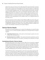
Layer 2 QoS: CoS on 802.1Q/P Ethernet Frame
The IEEE defined the 802.1Q frame for the purpose of implementing trunks between LAN
devices. The 4-byte 802.1Q header field that is inserted after the source MAC address on the
Ethernet header has a VLAN ID field for trunking purposes. A three-bit user priority field (PRI) is
available also and is called CoS (802.1p). CoS is used for QoS purposes; it can have one of eight
possible values, as shown in Table 3-2.
Figure 3-1 shows the 4-byte 802.1Q field that is inserted into the Ethernet header after the source
MAC address. In a network with IP Telephony deployed, workstations connect to the IP phone
Ethernet jack (marked PC), and the IP phone connects to the access layer switch (marked Switch).
Table 3-2 CoS Bits and Their Corresponding Decimal Values and Definitions
CoS (bits) CoS (in Decimal) IETF RFC791 Application
000 0 Routine Best-Effort Data
001 1 Priority Medium Priority Data
010 2 Immediate High Priority Data
011 3 Flash Call Signaling
100 4 Flash-Override Video Conferencing
101 5 Critical Voice Bearer
110 6 Internet Reserved
(inter-network control)
111 7 Network Reserved
(network control)
1763fm.book Page 98 Monday, April 23, 2007 8:58 AM
Classification and Marking 99
The IP phone sends 802.1Q/P frames to the workgroup switch. The frames leaving the IP phone
toward the workgroup (access) switch have the voice VLAN number in the VLAN ID field, and
their priority (CoS) field is usually set to 5 (decimal), which is equal to 101 binary, interpreted as
critical or voice bearer.
Figure 3-1 802.1Q/P Field
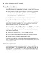
Layer 2 QoS: DE and CLP on Frame Relay and ATM (Cells)
Frame Relay and ATM QoS standards were defined and used (by ITU-T and FRF) before Internet
Engineering Task Force (IETF) QoS standards were introduced and standardized. In Frame Relay,
for instance, the forward explicit congestion notification (FECN), backward explicit congestion
notification (BECN), and discard eligible (DE) fields in the frame header have been used to
perform congestion notification and drop preference notification. Neither Frame Relay frames nor
ATM cells have a field comparable to the 3-bit CoS field previously discussed on 802.1P frames.
A Frame Relay frame has a 1-bit DE, and an ATM cell has a 1-bit cell loss priority (CLP) field that
essentially informs the transit switches whether the data unit is not (DE or CLP equal 0) or whether
it is (DE or CLP equal 1) a good candidate for dropping, should the need for dropping arise. Figure
3-2 displays the position of the DE field in the Frame Relay frame header.
Figure 3-2 DE Field on Frame Relay Frame Header
Ethernet 802.1Q/P Frame
Preamble SFD DA SA 802.1Q/P Type Data FCS
CoS
TPID
0×8100
16 bits
PRI
3 bits
CFI
1 bit
VLAN ID
12 bits
Frame Relay Frame
Flag
Frame Relay
Header
Information FCS Flag
DLCI C/R EA DLCI FECN BECN DE EA
Discard
Eligibility
(0 or 1)
1763fm.book Page 99 Monday, April 23, 2007 8:58 AM
100 Chapter 3: Classification, Marking, and NBAR
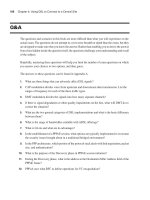
Layer 2 1/2 QoS: MPLS EXP Field
MPLS packets are IP packets that have one or more 4-byte MPLS headers added. The IP packet
with its added MPLS header is encapsulated in a Layer 2 protocol data unit (PDU) such as
Ethernet before it is transmitted. Therefore, the MPLS header is often called the SHIM or layer
2 1/2 header. Figure 3-3 displays an MPLS-IP packet encapsulated in an Ethernet frame. The EXP
(experimental) field within the MPLS header is used for QoS purposes. The EXP field was
designed as a 3-bit field to be compatible with the 3-bit IP precedence field on the IP header and
the 3-bit PRI (CoS) field in the 802.1Q header.
Figure 3-3 EXP Field in the MPLS Header
By default, as an IP packet enters an MPLS network, the edge router copies the three most
significant bits of the type of service (ToS) byte of the IP header to the EXP field of the MPLS
header. The three most significant bits of the ToS byte on the IP header are called the IP precedence
bits. The ToS byte of the IP header is now called the DiffServ field; the six most significant bits of
the DiffServ field are called the DSCP.
Instead of allowing the EXP field of MPLS to be automatically copied from IP precedence, the
administrator of the MPLS edge router can configure the edge router to set the EXP to a desired
value. This way, the customer of an MPLS service provider can set the IP precedence or DSCP
field to a value he wants, and the MPLS provider can set the EXP value on the MPLS header to a
value that the service provider finds appropriate, without interfering with the customer IP header
values and settings.
The DiffServ Model, Differentiated Services Code Point (DSCP),
and Per-Hop Behavior (PHB)
The DiffServ model was briefly discussed in Chapter 2, “IP Quality of Service.” Within the
DiffServ architecture, traffic is preferred to be classified and marked as soon (as close to the
DA SA
Type
×8847
Label
Exp S TTL
Experimental
Field Used for
QoS Marking
Ethertype
0×8847
means
MPLS-IP-Unicast
IP Packet
MPLS Header
48
Bits
48
Bits
16
Bits
20
Bits
3
Bits
8
Bits
1
Bit
1763fm.book Page 100 Monday, April 23, 2007 8:58 AM
The DiffServ Model, Differentiated Services Code Point (DSCP), and Per-Hop Behavior (PHB) 101
source) as possible. Marking of the IP packet was traditionally done on the three IP precedence
bits, but now, marking (setting) the six DSCP bits on the IP header is considered the standard
method of IP packet marking.
Each of the different DSCP values—in other words, each of the different combinations of DSCP
bits—is expected to stimulate every network device along the traffic path to behave in a certain
way and to provide a particular QoS treatment to the traffic. Therefore, within the DiffServ
framework, you set the DSCP value on the IP packet header to select a per-hop behavior (PHB).
PHB is formally defined as an externally observable forwarding behavior of a network node
toward a group of IP packets that have the same DSCP value. The group of packets with a common
DSCP value (belonging to the same or different sources and applications), which receive similar
PHB from a DiffServ node, is called a behavior aggregate (BA). The PHB toward a packet,
including how it is scheduled, queued, policed, and so on, is based on the BA that the packet
belongs to and the implemented service level agreement (SLA) or policy.
Scalability is a main goal of the DiffServ model. Complex traffic classification is performed as
close to the source as possible. Traffic marking is performed subsequent to classification. If
marking is done by a device under control of the network administration, the marking is said to be
trusted. It is best if the complex classification task is not repeated, and the PHB of the transit
network devices will solely depend on the trusted traffic marking. This way, the DiffServ model
has a coarse level of classification, and the marking-based PHB is applied to traffic aggregates or
behavior aggregates (BAs), with no per-flow state in the core.
Application-generated signaling (IntServ style) is not part of the DiffServ framework, and this
boosts the scalability of the DiffServ model. Most applications do not have signaling and Resource
Reservation Protocol (RSVP) capabilities. The DiffServ model provides specific services and QoS
treatments to groups of packets with common DSCP values (BAs). These packets can, and in large
scale do, belong to multiple flows. The services and QoS treatments that are provided to traffic
aggregates based on their common DSCP values are a set of actions and guarantees such as queue
insertion policy, drop preference, and bandwidth guarantee. The DiffServ model provides
particular service classes to traffic aggregates by classifying and marking the traffic first, followed
by PHB toward the marked traffic within the network core.
NOTE Some network devices cannot check or set Layer 3 header QoS fields (such as IP
precedence or DSCP). For example, simple Layer 2 wiring closet LAN switches can only check
and set the CoS (PRI) bits on the 802.1Q header.
1763fm.book Page 101 Monday, April 23, 2007 8:58 AM
102 Chapter 3: Classification, Marking, and NBAR
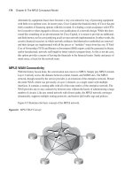
IP Precedence and DSCP
The initial efforts on IP QoS were based on the specifications provided by RFC 791 (1981), which
had called the 3 most significant bits of the ToS byte on the IP header the IP precedence bits. The
3 IP precedence bits can have one of eight settings. The larger the IP precedence value, the more
important the packet and the higher the probability of timely forwarding. Figure 3-4 displays an
IP packet and focuses on the IP ToS byte, particularly on the IP precedence bits. The eight IP
precedence combinations and their corresponding decimal values, along with the name given to
each IP precedence value, are also displayed in Figure 3-4. The IP precedence values 6 and 7, called
Internetwork Control and Network Control, are reserved for control protocols and are not allowed to
be set by user applications; therefore, user applications have six IP precedence values available.
Figure 3-4 IP Header ToS Byte and IP Precedence Values
Redefining the ToS byte as the Differentiated Services (DiffServ) field, with the 6 most significant
bits called the DSCP, has provided much more flexibility and capability to the new IP QoS efforts.
The 2 least significant bits of the DiffServ field are used for flow control and are called explicit
congestion notification (ECN) bits. DSCP is backward compatible with IP Precedence (IPP),
providing the opportunity for gradual deployment of DSCP-based QoS in IP networks. The
current DSCP value definitions include four PHBs:
■ Class selector PHB—With the least significant 3 bits of the DSCP set to 000, the class
selector PHB provides backward compatibility with ToS-based IP Precedence. When DSCP-
compliant network devices receive IP packets from non-DSCP compliant network devices,
they can be configured only to process and interpret the IP precedence bits. When IP packets
are sent from DSCP-compliant devices to the non-DSCP-compliant devices, only the 3 most
significant bits of the DiffServ field (equivalent to IP precedence bits) are set; the rest of the
bits are set to 0.
Ver Length
ToS
Flags
Checksum
IP Header
8 Bits
3 Bits 4 Bits 1 Bit
IP Precedence
IP Precedence
Decimal
IP Precedence
Binary
IP Precedence
Name
0 000 Routine
1 001 Priority
2 010 Immediate
3011 Flash
4 100 Flash-Override
5 101 Critical
6110 Internetwork Control
7 111 Network Control
1763fm.book Page 102 Monday, April 23, 2007 8:58 AM
The DiffServ Model, Differentiated Services Code Point (DSCP), and Per-Hop Behavior (PHB) 103
■ Default PHB—With the 3 most significant bits of the DiffServ/DSCP field set to 000, the
Default PHB is used for best effort (BE) service. If the DSCP value of a packet is not mapped
to a PHB, it is consequently assigned to the default PHB.
■ Assured forwarding (AF) PHB—With the most significant 3 bits of the DSCP field set to
001, 010, 011, or 100 (these are also called AF1, AF2, AF3, and AF4), the AF PHB is used
for guaranteed bandwidth service.
■ Expedited forwarding (EF) PHB—With the most significant 3 bits of the DSCP field set to
101 (the whole DSCP field is set to 101110, decimal value of 46), the EF PHB provides low
delay service.
Figure 3-5 displays the DiffServ field and the DSCP settings for the class selector, default, AF, and
EF PHBs.
Figure 3-5 IP Header DS Field and DSCP PHBs
The EF PHB provides low delay service and should minimize jitter and loss. The bandwidth that
is dedicated to EF must be limited (capped) so that other traffic classes do not starve. The queue
that is dedicated to EF must be the highest priority queue so that the traffic assigned to it gets
through fast and does not experience significant delay and loss. This can only be achieved if the
volume of the traffic that is assigned to this queue keeps within its bandwidth limit/cap. Therefore,
successful deployment of EF PHB is ensured by utilizing other QoS techniques such as admission
control. You must remember three important facts about the EF PHB:
■ It imposes minimum delay.
■ It provides bandwidth guarantee.
■ During congestion, EF polices bandwidth.
0ECNECN
___
000
000
__
0
001
__
010
__
011
__
100
__
0
0
0
0
101 110
Class Selector PHB
Default PHB
Assured Forwarding
(AF) PHB
Expedited Forwarding
(EF) PHB
6 DSCP Bits
DS Field
1763fm.book Page 103 Monday, April 23, 2007 8:58 AM
104 Chapter 3: Classification, Marking, and NBAR
Older applications (non-DSCP compliant) set the IP precedence bits to 101 (decimal 5, called Critical)
for delay-sensitive traffic such as voice. The most significant bits of the EF marking (101110) are 101,
making it backward compatible with the binary 101 IP precedence (Critical) setting.
The AF PHB as per the standards specifications provides four queues for four classes of traffic
(AFxy): AF1y, AF2y, AF3y, and AF4y. For each queue, a prespecified bandwidth is reserved. If
the amount of traffic on a particular queue exceeds the reserved bandwidth for that queue, the
queue builds up and eventually incurs packet drops. To avoid tail drop, congestion avoidance
techniques such as weighted random early detection (WRED) are deployed on each queue. Packet
drop is performed based on the marking difference of the packets. Within each AFxy class, y
specifies the drop preference (or probability) of the packet. Some packets are marked with
minimum probability/preference of being dropped, some with medium, and the rest with
maximum probability/preference of drop. The y part of AFxy is one of 2-bit binary numbers 01,
10, and 11; this is embedded in the DSCP field of these packets and specifies high, medium, and
low drop preference. Note that the bigger numbers here are not better, because they imply higher
drop preference. Therefore, two features are embedded in the AF PHB:
■ Four traffic classes (BAs) are assigned to four queues, each of which has a minimum reserved
bandwidth.
■ Each queue has congestion avoidance deployed to avoid tail drop and to have preferential drops.
Table 3-3 displays the four AF classes and the three drop preferences (probabilities) within each
class. Beside each AFxy within the table, its corresponding decimal and binary DSCP values are
also displayed for your reference.
Table 3-3 The AF DSCP Values
Class
Drop Probability
Low Drop Medium Drop High Drop
Class 1 AF11
DSCP 10: (001010)
AF12
DSCP 12: (001100)
AF13
DSCP 14: (001110)
Class 2 AF21
DSCP 18: (010010)
AF22
DSCP 20: (010100)
AF23
DSCP 22: (010110)
Class 3 AF31
DSCP 26: (011010)
AF32
DSCP 28: (011100)
AF33
DSCP 30: (011110)
Class 4 AF41
DSCP 34: (100010)
AF42
DSCP 36: (100100)
AF43
DSCP 38: (100110)
1763fm.book Page 104 Monday, April 23, 2007 8:58 AM
The DiffServ Model, Differentiated Services Code Point (DSCP), and Per-Hop Behavior (PHB) 105
You must remember a few important facts about AF:
■ The AF model has four classes: AF1, AF2, AF3, and AF4; they have no advantage over each
other. Different bandwidth reservations can be made for each queue; any queue can have more
or less bandwidth reserved than the others.
■ On a DSCP-compliant node, the second digit (y) of the AF PHB specifies a drop preference
or probability. When congestion avoidance is applied to an AF queue, packets with AFx3
marking have a higher probability of being dropped than packets with AFx2 marking, and
AFx2 marked packets have a higher chance of being dropped than packets with AFx1
marking, as the queue size grows.
■ You can find the corresponding DSCP value of each AFxy in decimal using this formula:
DSCP (Decimal) = 8x + 2y.
For example, the DSCP value for AF31 is 26 = (8 * 3) + (2 * 1).
■ Each AFx class is backward compatible with a single IP precedence value x. AF1y maps to
IP precedence 1, AF2y maps to IP precedence 2, AF3y maps to IP precedence 3, and AF4y
maps to IP precedence 4.
■ During implementation, you must reserve enough bandwidth for each AF queue to avoid
delay and drop in each queue. You can deploy some form of policing or admission control so
that too much traffic that maps to each AF class does not enter the network or node. The exact
congestion avoidance (and its parameters) that is applied to each AF queue is also dependent
on the configuration choices.
■ If there is available bandwidth and an AF queue is not policed, it can consume more
bandwidth than the amount reserved.
Most of the fields within the IP packet header in a transmission do not change from source to
destination. (However, TTL, checksum, and sometimes the fragment-related fields do change.)
The Layer 3 QoS marking on the packet can be preserved, but the Layer 2 QoS marking must be
rewritten at every Layer 3 router because the Layer 3 router is responsible for rewriting the Layer
2 frame. The packet marking is used as a classification mechanism on each ingress interface of a
subsequent device. The BA of the service class that the traffic maps to must be committed. To
guarantee end-to-end QoS, every node in the transmission path must be QoS capable. QoS
differentiated service in MPLS networks is provided based on the EXP bits on the MPLS header.
As a result, it is important that at certain points in the network, such as at edge devices, mapping
is performed between IP precedence, DSCP, CoS, MPLS, or other fields that hold QoS markings.
The mapping between 802.1Q/P CoS, MPLS EXP, and IP precedence is straightforward because
all of them are based on the old-fashioned 3-bit specifications of the 1980s. Mapping the DSCP
PHBs to those 3-bit fields requires some administrative decisions and compromises.
1763fm.book Page 105 Monday, April 23, 2007 8:58 AM
106 Chapter 3: Classification, Marking, and NBAR
QoS Service Class
Planning and implementing QoS policies entails three main steps:
Step 1 Identify network traffic and its requirements.
Step 2 Divide the identified traffic into classes.
Step 3 Define QoS policies for each class.
In Step 1, you use tools such as NBAR to identify the existing traffic in the network. You might
discover many different traffic types. In Step 1, you must then recognize and document the
relevance and importance of each recognized traffic type to your business.
In Step 2, you group the network traffic into traffic or service classes. Each traffic or service class,
composed of one or more traffic types, receives a specific QoS treatment. Each service class is
created for one or more traffic types (a single group) that is called a BA. A common model used
by service providers, called the customer model, defines four service classes:
■ Mission critical
■ Transactional
■ Best-effort
■ Scavenger
A traffic class can be defined based on many factors. For example, these criteria, should they be
appropriate, can also be used to define traffic classes: an organization or department, a customer
(or a set of them), an application (or a group of applications, such as Telnet, FTP, SAP, Oracle), a
user or group of users (by location, job description, workstation MAC address), a traffic
destination, and so on.
Step 3 in planning and implementing QoS policies using QoS service classes is defining policies
for each service class. This step requires an understanding of the QoS needs of the traffic and
applications that are within your network. When you design the policies, be careful not to make
too many classes and make the matter too complex and over-provisioned. Limiting the service
classes to four or five is common. Also, do not assign too many applications and traffic to the high-
priority and mission-critical classes, because assigning a large percentage of traffic to those classes
will ultimately have a negative effect. Some of the existing common traffic classes are as follows:
■ Voice applications (VoIP)
■ Mission-critical applications, such as Oracle and SAP
■ Transactional/Interactive applications, such as Telnet and SSH
1763fm.book Page 106 Monday, April 23, 2007 8:58 AM
QoS Service Class 107
■ Bulk applications such as FTP and TFTP
■ Best-effort applications, such as WWW and e-mail
■ Scavenger applications, such as Napster and Kazaa
You can find many sources of information and recommendations on QoS design and implementation;
however, each network is unique and requires special attention. It is important to implement the
QoS policies throughout the network and in a consistent way. Keep in mind the following two
important points:
■ If you do not implement QoS policies in certain parts of the network, the QoS offering of your
network will be incomplete, unpredictable, and inadequate.
■ Because not all network devices have consistent and complete capabilities and features, you
must map QoS techniques and features well. That way, the behavior of the diverse devices
within your network will be consistent and in-line with your policies.
One required task during the QoS policy implementation stage is mapping and translating between
CoS, DSCP, IP precedence, and MPLS EXP markings. Table 3-4 shows the Cisco recommended
mappings between Layer 2 CoS, IP precedence, DSCP, PHB and Class Selector Name, and their
corresponding traffic types.
Table 3-4 Mapping Different Markings to Different Traffic Types
Cisco AutoQoS
Class
Layer 2 CoS or IP
Precedence
DSCP Value
in Decimal
DSCP Value
in Binary Code Name
Best Effort 00000000 BE
(Best Effort)
Scavenger 18001000 CS1
(Class Selector 1)
Bulk Data 110
12
14
001010
001100
001110
AF11
AF12
AF13
Network
Management
216010000 CS2
(Class Selector 2)
1763fm.book Page 107 Monday, April 23, 2007 8:58 AM
108 Chapter 3: Classification, Marking, and NBAR
Trust Boundaries
End-system devices such as personal computers, IP phones, IP conference devices, and video
conference gateways, plus switches and routers at different levels of the network hierarchy, can
mark the IP packets or the encapsulating frames such as 802.1Q/P. One of the design and policy
decisions you have to make is where to place your network trust boundary. The trust boundary
forms a perimeter on your network; your network respects and trusts (does not override) the
markings that the devices on or inside this perimeter (trust boundary) make. Markings that devices
make outside the trust boundary are often reset, or at least checked and modified if necessary. The
devices that check and reset the markings of the traffic received from the untrusted devices
(devices outside the trust boundary), form the trust boundary of the network. The devices that form
the trust boundary are the first set of devices that are trusted because they forward traffic toward
the network core. It is considered good practice to place the trust boundary as close to the traffic
source (and away from the network core) as possible.
You should certainly try to place the trust boundary as close to the network edge as possible.
However, two other factors can affect your decision. First, the trusted device must be under your
administration and control; at the very least, you should be confident that its marking is in-line
with your QoS policies. Second, different devices have different capabilities and feature sets with
respect to the ability to check and set/reset various QoS markings such as CoS and DSCP. With all
Cisco AutoQoS
Class
Layer 2 CoS or IP
Precedence
DSCP Value
in Decimal
DSCP Value
in Binary Code Name
Telephony
Signaling
326011010 AF31
Local Mission
Critical
328
30
011100
011110
AF32
AF33
Streaming Media
Traffic
432100000 CS4
(Class Selector 4)
Interactive Video
Traffic
434
36
38
100010
100100
100110
AF41
AF42
AF43
Interactive Voice
Bearer Traffic
546101110 EF
Table 3-4 Mapping Different Markings to Different Traffic Types (Continued)
1763fm.book Page 108 Monday, April 23, 2007 8:58 AM
Trust Boundaries 109
facts considered, the trust boundary is implemented at one of the following network hierarchy
layers:
■ End system
■ Access switch
■ Distribution switch
Figure 3-6 depicts three scenarios with the trust boundary placed on the IP phone, the access
switch, and the distribution switch. The end systems, except for telephony and conference
systems, are generally recommended not to be trusted. New microcomputer operating systems
such as the Linux and Microsoft operating systems make it possible to set the DSCP or CoS field
on the transmitted traffic. Access switches, if they have the capability, are generally configured to
(or by default do) trust the markings set by the IP phone only. If the access switch does not have
any or enough QoS capabilities, you might have to shift the trust boundary to the distribution layer
switch.
Figure 3-6 Trust Boundary Placement Choices
In the first scenario displayed in Figure 3-6, the trust boundary is placed on the Cisco IP phone.
The phone sets/resets the CoS field to 0 (000 binary) for the frames it receives from the PC as it
forwards them to the switch. The CoS value on the IP phone-generated frames that are carrying
voice signaling is set to 3 (011 binary), and it is set to 5 (101 binary) for those that are carrying
Network
Core
Access
Switch
Tr ust Boundary
IP
Distribution
Switch
PC
Access
802.1Q/p
Tr unk
Connection
1
Network
Core
Tr ust Boundary
PC
Access
Tr unk
Connection
2
Network
Core
Tr ust Boundary
PC
Access
Tr unk
Connection
3
1763fm.book Page 109 Monday, April 23, 2007 8:58 AM
110 Chapter 3: Classification, Marking, and NBAR
voice. The access switch is configured to trust the markings of the traffic received on the port that
the Cisco IP phone is connected to. But how does the switch know that a Cisco IP phone, and not
another IP device such as a PC, is connected to that port? The switch discovers that a Cisco IP
phone is connected to its port by means of the Cisco Discovery Protocol version 2 (CDP v2) that
both the switch and the IP phone are supposed to have enabled. If the switch does not discover an
IP phone, it does not extend the trust boundary to the end device and dynamically shifts the trust
boundary to itself (the access switch).
In the second scenario, the PC is connected to the access switch, the trusted device. The access
switch must be configured to check (and reset if necessary) the CoS field in case it receives
802.1Q/P frames from the PC (rare case). Some access switches are capable of checking (and
setting) the IP header QoS fields (ToS field’s IP precedence or DSCP). When the traffic from the
PC is forwarded toward the distribution switch, because the connection between the access switch
and distribution switch is usually an 802.1Q/P trunk, the access switch can set the CoS field (and
the DSCP field, if the switch has the capability) of the outgoing traffic to certain values based on
QoS policies and the traffic type. For instance, the PC can run several different applications,
including Cisco IP Communicator. In that case, if the marking of the traffic coming from the PC
is not trusted, classification and marking of the traffic must happen on the trusted access switch.
Network QoS treatments and PHBs are based on the markings that happen at the trusted boundary.
The third scenario in Figure 3-6 shows the trust boundary placed on the distribution switch. This
usually happens when the access switch does not have enough or complete QoS classification,
policing, or marking capabilities. It is also possible that the access switch is not under your
administrative control; this is quite common in data center environments. For instance, the access
switch might be able to set or reset the CoS field of the 802.1Q/P header but might not be able to
set or reset the DSCP field on the IP packet header. The distribution switch has QoS capabilities
and features so that it can do classification, policing, and marking based on CoS or DSCP (or IP
precedence).
Network Based Application Recognition (NBAR)
NBAR is a Cisco IOS feature that can be used to perform three tasks:
■ Protocol discovery
■ Traffic statistics collection
■ Traffic classification
Because NBAR can discover which applications and protocols are running on your network and
display volume and statistics about them, you can use it as a powerful yet simple tool to form the
definitions of your network traffic classes (BAs). You can also use NBAR within class-based (CB)
marking or other MQC-based tools to classify packets for purposes such as marking, policing, and
1763fm.book Page 110 Monday, April 23, 2007 8:58 AM
Network Based Application Recognition (NBAR) 111
queuing. NBAR is a powerful protocol discovery and classification tool, but the overhead it
imposes is considered small or medium. The amount of CPU utilization increase that a router
running NBAR experiences depends on the amount of traffic and the router CPU type and speed.
NBAR recognizes a limited number of protocols. However, you can expand the list of recognized
protocols by loading new Packet Description Language Modules (PDLMs), published by Cisco
systems, into your device (flash memory) and making a reference to the new PDLM in the device
configuration. PDLMs are files that Cisco Systems publishes; these files contain rules that NBAR
uses to recognize protocols and applications. A new PDLM can be loaded in the flash memory of
the Cisco device and then referenced within its configuration without a need to perform an IOS
upgrade or reload the device. Cisco Systems makes up-to-date PDLMs available to registered
users on Cisco Connection Online (CCO) at www.cisco.com/cgi-bin/tablebuild.pl/pdlm.
Before you can design a classification and marking scheme for your network, you need to identify
and recognize the existing traffic for your network. The NBAR protocol-discovery feature
provides a simple way to discover and report the applications and protocols that transit (in and out)
a particular interface of a network device you choose. Protocol discovery discovers and reports on
the protocols and applications that NBAR supports (plus those added by the loaded PDLMs). Key
statistics are also reported on the discovered protocols and applications. Examples of the statistics
that NBAR protocol discovery reports on each protocol are the total number of input and output
packets and bytes and the input and output bit rates. The list of discovered protocols and
applications, plus the associated statistics, which NBAR reports, are valuable when you want to
define your traffic classes and their QoS policies.
NBAR can classify traffic by inspecting bytes beyond the network and transport layer headers.
This is called subport classification. This means that NBAR looks into the segment (TCP or UDP)
payload and classifies based on that content. For example, NBAR can classify HTTP traffic based
on the URL; it can also classify based on MIME type.
NBAR has some limitations. First, it does not function on the Fast EtherChannel logical interface.
Second, NBAR can only handle up to 24 concurrent URLs, hosts, or MIME types. Third, NBAR
only analyzes the first 400 bytes of the packet. Fourth, it only supports CEF and does not work if
another switching mode is used. It does not support multicast packets, fragmented packets, and
packets that are associated with secure HTTP (URL, host, or MIME classification). NBAR does
not analyze or recognize the traffic that is destined to or emanated from the router where NBAR
is running.
Configuring classification without NBAR is mostly dependent on writing and maintaining access
lists. Using NBAR for classification is not only simpler than using access lists, but NBAR also
offers capabilities beyond those offered by access lists. NBAR can do stateful inspection of flows.
This means that it can discover the dynamic TCP or UDP port numbers that are negotiated at
connection establishment time by inspecting the control session packets. For example, a TFTP
1763fm.book Page 111 Monday, April 23, 2007 8:58 AM
112 Chapter 3: Classification, Marking, and NBAR
session is initiated using the well-known UDP port 69, but the two ends of the session negotiate
other ports for the remainder of the session traffic. NBAR also supports some non-IP and non-
TCP/non-UDP protocols and applications such as Internetwork Packet Exchange (IPX), IPsec,
and GRE. Finally, as stated already, NBAR is able to discover and classify by deep packet
inspection, too. This means that NBAR can inspect the payload of TCP and UDP segments (up to
the 400
th
byte of the packet) and classify. HTTP sessions can be classified by URL, hostname, or
MIME type.
Cisco IOS Commands to Configure NBAR
To enhance the list of protocols that NBAR recognizes through a PDLM, download the PDLM
from CCO and copy it into the flash or on a TFTP server. Next, enter the following command,
which refers to the PDLM name in URL format:
Router(config)#
ii
ii
pp
pp
nn
nn
bb
bb
aa
aa
rr
rr
pp
pp
dd
dd
ll
ll
mm
mm
pdlm-name
The URL, for example, can be flash://citrix.pdlm, referring to the citrix.pdlm file in flash memory.
The URL can also refer to a file on a TFTP server, such as tftp://192.168.19.66/citrix.pdlm.
To modify the port number that NBAR associates to a protocol name or to add a port to the list of
ports associated to a protocol name, use this command:
Router(config)# ii
ii
pp
pp
nn
nn
bb
bb
aa
aa
rr
rr
pp
pp
oo
oo
rr
rr
tt
tt
mm
mm
aa
aa
pp
pp
protocol-name
[tt
tt
cc
cc
pp
pp
| uu
uu
dd
dd
pp
pp
]
port-number
The preceding command configures NBAR to search for a protocol or protocol name using a port
number other than the well-known one. You can specify up to 16 additional port numbers.
To see the current NBAR protocol-to-port mapping, use the following show command:
Router# ss
ss
hh
hh
oo
oo
ww
ww
ii
ii
pp
pp
nn
nn
bb
bb
aa
aa
rr
rr
pp
pp
oo
oo
rr
rr
tt
tt
mm
mm
aa
aa
pp
pp
[
protocol-name
]
Example 3-1 displays partial sample output of the preceding command.
To enable NBAR protocol discovery on a router interface, first ensure that CEF is enabled on that
interface. CEF is turned on using the IP CEF command from Cisco IOS global configuration
mode. Next, enter the following command in the interface configuration mode:
Router(config-if)# ii
ii
pp
pp
nn
nn
bb
bb
aa
aa
rr
rr
pp
pp
rr
rr
oo
oo
tt
tt
oo
oo
cc
cc
oo
oo
ll
ll
dd
dd
ii
ii
ss
ss
cc
cc
oo
oo
vv
vv
ee
ee
rr
rr
yy
yy
Example 3-1 Displaying NBAR Protocol-to-Port Mapping
Router# ss
ss
hh
hh
oo
oo
ww
ww
ii
ii
pp
pp
nn
nn
bb
bb
aa
aa
rr
rr
pp
pp
oo
oo
rr
rr
tt
tt
mm
mm
aa
aa
pp
pp
port-map bgp tcp 179
port-map dhcp udp 67 68
port-map dns udp 53
port-map dns tcp 53
1763fm.book Page 112 Monday, April 23, 2007 8:58 AM
Cisco IOS Commands to Configure NBAR 113
To display the discovered protocols and the statistics gathered for each discovered protocol, enter
the following show command. Note that unless you specify an interface, the output will include
the statistics gathered for all interfaces (back to back):
Router# ss
ss
hh
hh
oo
oo
ww
ww
ii
ii
pp
pp
nn
nn
bb
bb
aa
aa
rr
rr
pp
pp
rr
rr
oo
oo
tt
tt
oo
oo
cc
cc
oo
oo
ll
ll
dd
dd
ii
ii
ss
ss
cc
cc
oo
oo
vv
vv
ee
ee
rr
rr
yy
yy
Sample output of the preceding command is shown in Example 3-2.
You can use NBAR to recognize and classify protocols that use static port numbers; NBAR can
do the same for protocols that dynamically negotiate port numbers. If you want NBAR to classify
network traffic based on protocol and subsequently apply certain QoS policies to each traffic class,
use MQC class map and refer to the desired NBAR protocol with a match statement. The
following is the syntax for the match statement within a class map:
Router(config-cmap)# mm
mm
aa
aa
tt
tt
cc
cc
hh
hh
pp
pp
rr
rr
oo
oo
tt
tt
oo
oo
cc
cc
oo
oo
ll
ll
protocol-name
The protocol-name that is referred by the class map match protocol statement is an NBAR-
supported protocol such as ip, arp, compressed tcp, cdp, dlsw, ipx, and so on. Do not forget that
you can specify additional ports (besides the well-known ports) for each protocol by configuring
the previously introduced ip nbar port-map command. Also, to expand the list of NBAR-
supported protocols, you can load new PDLMs in your device, as discussed earlier in this section.
To use NBAR for classification and marking of traffic belonging to static-port protocols and to
apply the policy to an interface, you have to perform the following tasks:
■ Enable NBAR protocol discovery.
■ Configure a traffic class using the MQC class map.
■ Configure a QOS policy using the MQC policy map.
Example 3-2 Displaying NBAR protocol-discovery Results
Router# ss
ss
hh
hh
oo
oo
ww
ww
ii
ii
pp
pp
nn
nn
bb
bb
aa
aa
rr
rr
pp
pp
rr
rr
oo
oo
tt
tt
oo
oo
cc
cc
oo
oo
ll
ll
dd
dd
ii
ii
ss
ss
cc
cc
oo
oo
vv
vv
ee
ee
rr
rr
yy
yy
Ethernet 0/0/0
Input Output
Protocol Packet Count Packet Count
Byte Count Byte Count
5 minute bit rate (bps) 5 minute bit rate (bps)
eigrp 60 0
3600 0
0 0
bgp 0 0
0 0
0 0
1763fm.book Page 113 Monday, April 23, 2007 8:58 AM
114 Chapter 3: Classification, Marking, and NBAR
■ Apply the policy to the interface(s).
■ Expand the NBAR protocol ports or PDLM protocols if needed.
Example 3-3 shows partial configuration of a router with a policy called www-ltd-bw (implying
limited bandwidth for web browsing or HTTP protocol) applied to its serial 1/1 interface. The first
line shows that TCP ports 80 and 8080 are defined for HTTP. The configured class map defines a
traffic class called www, which includes all traffic classified by NBAR as http. The policy map
called www-ltd-bw is applied to the outgoing traffic of the serial 1/1 interface using the service-
policy output command. The policy map www-ltd-bw specifies that the traffic classified as www
is assigned to a queue with a 512-Kbps bandwidth reservation.
In Example 3-3, the command ip nbar protocol-discovery is applied to the serial 1/1 interface.
In the past (earlier Cisco IOS releases), you had to apply this command to the interface before you
could apply a service policy that used NBAR (through the match protocol name command);
however, as of Cisco IOS 12.2T, this is no longer necessary. The ONT course does not mention
this fact in its initial release, so for examination purposes, you might want to do it the old-
fashioned way and apply the ip nbar protocol-discovery command to the interface.
You can also use NBAR to do traffic classification for stateful protocols, those that negotiate the
data session port numbers during the initial control session. You still need to take three steps:
1. Configure a traffic class using MQC class map.
(Within the class map, the match statement references the stateful protocol such as TFTP).
2. Configure a QOS policy using MQC policy map.
3. Apply the policy to the interface(s).
Example 3-3 Implementing QoS Policy Using NBAR for Static Protocols
ip nbar port-map http tcp 80 8080
!
class-map www
match protocol http
!
policy-map www-ltd-bw
class www
bandwidth 512
!
interface serial 1/1
ip nbar protocol-discovery
service-policy output www-ltd-bw
!
1763fm.book Page 114 Monday, April 23, 2007 8:58 AM
Cisco IOS Commands to Configure NBAR 115
One of the most attractive and powerful NBAR features is its ability to do deep packet inspection.
Four popular uses of NBAR deep packet inspection are as follows:
■ Classifying traffic based on the hostname or the URL after the hostname in the HTTP GET
requests
■ Classifying traffic based on the MIME type
■ Classifying traffic belonging to fast-track protocols file transfers using regular expressions
that match strings
■ Classifying traffic based on the RTP payload type or CODEC
The match protocol commands required within MQC class map, to classify traffic according to
the preceding criteria, are as follows:
Router(config-cmap)# mm
mm
aa
aa
tt
tt
cc
cc
hh
hh
pp
pp
rr
rr
oo
oo
tt
tt
oo
oo
cc
cc
oo
oo
ll
ll
hh
hh
tt
tt
tt
tt
pp
pp
uu
uu
rr
rr
ll
ll
url-string
Router(config-cmap)# mm
mm
aa
aa
tt
tt
cc
cc
hh
hh
pp
pp
rr
rr
oo
oo
tt
tt
oo
oo
cc
cc
oo
oo
ll
ll
hh
hh
tt
tt
tt
tt
pp
pp
hh
hh
oo
oo
ss
ss
tt
tt
host-name
Router(config-cmap)# mm
mm
aa
aa
tt
tt
cc
cc
hh
hh
pp
pp
rr
rr
oo
oo
tt
tt
oo
oo
cc
cc
oo
oo
ll
ll
hh
hh
tt
tt
tt
tt
pp
pp
mm
mm
ii
ii
mm
mm
ee
ee
mime-type
Router(config-cmap)# mm
mm
aa
aa
tt
tt
cc
cc
hh
hh
pp
pp
rr
rr
oo
oo
tt
tt
oo
oo
cc
cc
oo
oo
ll
ll
ff
ff
aa
aa
ss
ss
tt
tt
tt
tt
rr
rr
aa
aa
cc
cc
kk
kk
ff
ff
ii
ii
ll
ll
ee
ee
tt
tt
rr
rr
aa
aa
nn
nn
ss
ss
ff
ff
ee
ee
rr
rr
rr
rr
ee
ee
gg
gg
uu
uu
ll
ll
aa
aa
rr
rr
ee
ee
xx
xx
pp
pp
rr
rr
ee
ee
ss
ss
ss
ss
ii
ii
oo
oo
nn
nn
Router(config-cmap)#
mm
mm
aa
aa
tt
tt
cc
cc
hh
hh
pp
pp
rr
rr
oo
oo
tt
tt
oo
oo
cc
cc
oo
oo
ll
ll
rr
rr
tt
tt
pp
pp
[aa
aa
uu
uu
dd
dd
ii
ii
oo
oo
|
vv
vv
ii
ii
dd
dd
ee
ee
oo
oo
|
pp
pp
aa
aa
yy
yy
ll
ll
oo
oo
aa
aa
dd
dd
tt
tt
yy
yy
pp
pp
ee
ee
payload-type-string
]
Example 3-4 shows three class maps: from-cisco, whats-up, and cool-jpegs. The class map from-
cisco matches any HTTP GET request from hosts whose names begin with cisco. cisco* is a
regular expression that matches any string that begins with characters cisco (followed by zero or
more characters). Special characters such as *, which means zero or more characters (wildcard),
make writing regular expressions a lot easier. The class map whats-up matches HTTP packets
based on any URL containing the string /latest/whatsnew followed by zero or more characters. The
last class map in Example 3-4, cool-jpegs, classifies packets based on the Joint Photographics
Expert Group (JPEG) MIME type.
Example 3-4 Using NBAR to Match HTTP Hostname, URL, and MIME Type
!
class-map from-cisco
match protocol http host cisco*
!
class-map whats-up
match protocol http url /latest/whatsnew*
!
class-map cool-jpegs
match protocol http mime “*jpeg”
!
1763fm.book Page 115 Monday, April 23, 2007 8:58 AM
116 Chapter 3: Classification, Marking, and NBAR
For your reference only (not for the purpose of exam preparation), Table 3-5 presents a few useful
special characters you can use within regular expressions of the class map match statement.
You can also use NBAR deep packet inspection to match traffic from FastTrack peer-to-peer
protocols such as Kazaa and Grokster. To configure NBAR to match FastTrack peer-to-peer traffic,
use the following command in class map configuration mode:
Router(config-cmap)# mm
mm
aa
aa
tt
tt
cc
cc
hh
hh
pp
pp
rr
rr
oo
oo
tt
tt
oo
oo
cc
cc
oo
oo
ll
ll
ff
ff
aa
aa
ss
ss
tt
tt
tt
tt
rr
rr
aa
aa
cc
cc
kk
kk
ff
ff
ii
ii
ll
ll
ee
ee
tt
tt
rr
rr
aa
aa
nn
nn
ss
ss
ff
ff
ee
ee
rr
rr
reg-exp
Please note that the preceding command syntax expects a regular expression to identify a specific
FastTrack traffic. Gnutella traffic can be classified similarly using NBAR, by changing the
keyword FastTrack to Gnutella.
Example 3-5 shows three class maps. The class map called fasttrack1 configures NBAR to match
all FastTrack traffic. In the second class map, all FastTrack files that have the .mpeg extension are
classified into traffic class fasttrack2. Class map fasttrack3 specifies that all FastTrack traffic that
contains the string “cisco” is part of the traffic class called fasttrack3.
Table 3-5 Special Strings and Characters for Regular Expressions
Character or String Description
* Match zero or more characters in this position.
? Match any one character in this position.
|
It means OR. Match one of a choice of characters on either side of the |
symbol.
( | )
Match one of a choice of characters inside the parentheses on either side of
the | symbol. For example, xyz.(gif|jpg) matches either xyz.gif or xyz.jpg.
[ ]
Match any character in the range specified, or one of the special characters.
For example, [0-9] is any single digit; [*] matches the * character, and [[]
matches the [ character.
Example 3-5 Using NBAR to Match FastTrack Protocol Traffic
!
class-map fasttrack1
match protocol fasttrack file-transfer “*”
!
class-map fasttrack2
match protocol fasttrack file-transfer “*.mpeg”
!
class-map fasttrack3
match protocol fasttrack file-transfer “*cisco*”
!
1763fm.book Page 116 Monday, April 23, 2007 8:58 AM
Cisco IOS Commands to Configure NBAR 117
The Real-Time Transport Protocol (RTP) is considered the transport protocol of choice for real-
time audio and video. It adds a header above the UDP header to include information such as
reconstruction timestamp and sequence number, plus security and content identification. RTP has
a control protocol sister called Real-Time Protocol Control Protocol (RTCP). Whereas RTP uses
the UDP even-numbered ports (starting with 16384 by default), RTCP uses the UDP odd-number
ports. NBAR deep packet inspection allows you to do classification based on RTP payload type
(audio or video) or do a deeper classification based on audio or video CODEC type. The syntax to
configure NBAR to match RTP traffic in class map configuration mode is as follows:
Router(config-cmap)#
mm
mm
aa
aa
tt
tt
cc
cc
hh
hh
pp
pp
rr
rr
oo
oo
tt
tt
oo
oo
cc
cc
oo
oo
ll
ll
rr
rr
tt
tt
pp
pp
[aa
aa
uu
uu
dd
dd
ii
ii
oo
oo
|
vv
vv
ii
ii
dd
dd
ee
ee
oo
oo
|
pp
pp
aa
aa
yy
yy
ll
ll
oo
oo
aa
aa
dd
dd
tt
tt
yy
yy
pp
pp
ee
ee
payload-type-string
]
In the preceding command syntax, the optional keyword audio specifies matching by audio
payload type. (Values in the range of 0 to 23 are reserved for audio traffic.) Similarly, the optional
keyword video specifies matching by video payload type. (Values in the range of 24 to 33 are
reserved for video traffic.) If you use the optional keyword payload-type, you can specify (using
a string) matching by a specific payload type value, providing more granularity than is available
with the audio or video keywords. A payload string argument can contain commas to separate
payload type values and hyphens to indicate a range of payload type values.
Example 3-6 shows two class maps. The first class map is called voice, and as the name implies,
it matches the RTP audio protocol. The class map called video matches the RTP video protocol.
Example 3-6 Using NBAR to Match RTP Protocol Traffic
!
class-map voice
mm
mm
aa
aa
tt
tt
cc
cc
hh
hh
pp
pp
rr
rr
oo
oo
tt
tt
oo
oo
cc
cc
oo
oo
ll
ll
RR
RR
TT
TT
PP
PP
aa
aa
uu
uu
dd
dd
ii
ii
oo
oo
!
class-map video
mm
mm
aa
aa
tt
tt
cc
cc
hh
hh
pp
pp
rr
rr
oo
oo
tt
tt
oo
oo
cc
cc
oo
oo
ll
ll
RR
RR
TT
TT
PP
PP
vv
vv
ii
ii
dd
dd
ee
ee
oo
oo
!
1763fm.book Page 117 Monday, April 23, 2007 8:58 AM
118 Chapter 3: Classification, Marking, and NBAR
Foundation Summary
The “Foundation Summary” is a collection of information that provides a convenient review of
many key concepts in this chapter. If you are already comfortable with the topics in this chapter,
this summary can help you recall a few details. If you just read this chapter, this review should
help solidify some key facts. If you are doing your final preparation before the exam, the
information in this section is a convenient way to review the day before the exam.
Table 3-6 summarizes the major topics in this chapter.
Table 3-6 Summary of Classification, Marking, and NBAR
Topic Summary
Purpose of packet
classification
Packet classification is a QoS mechanism that distinguishes and
divides network traffic into traffic classes or behavior aggregates
(BAs).
Purpose of packet marking Packets, frames, and some other protocol data units (PDUs) have a
special field designed for QoS purposes. Marking is a QoS
mechanism that sets this field to a common value on packets that
belong to the same traffic/service class (BA) and sets them to
different values on packets that belong to different classes.
Classification and marking at
the data link layer
Different data link layer protocol data units (PDUs) have different
fields for QoS classification and marking purposes. On 802.1Q/P or
ISL frames, the 3-bit PRI (CoS) field is used for that purpose. On
Frame Relay frames, the DE bit is used for that purpose, and on
AMT cells, the CLP bit is used. On the MPLS header (layer 2∫) the
3-bit EXP field is used for QoS purposes.
PHB A per-hop behavior (PHB) is an externally observable forwarding
behavior applied at a DiffServ-compliant node to a DiffServ BA.
Class selector PHB (DSCP) The class-selector PHB is a set of DSCP values that make DSCP
backward compatible with IPP (IP precedence). The least significant
bits of the class selectors (CS1 through CS7) are 000.
AF PHB The assured forwarding (AF) PHB provides four queues for four
classes of traffic. Bandwidth reservation can be made for each AF
queue. Each AF has three DSCP values associated to it so that
differentiated drop policy can be applied to the packets in the same
AF queue.
EF PHB The expedited forwarding (EF) PHB provides a priority queue with
guaranteed but policed bandwidth. EF PHB is ideal for delay-
sensitive traffic as long as this type of traffic is not oversubscribed.
1763fm.book Page 118 Monday, April 23, 2007 8:58 AM
Foundation Summary 119
Topic Summary
QoS service class QoS service class is a logical grouping of packets that, as per the
administrative policy definitions, are required to receive the same
QoS treatment.
Trust boundary Marking is recommended to take place as close to the ingress edge
of the network as possible. Marking, however, must be done by a
trusted device. The ingress edge/perimeter of the network where the
trusted devices reside and perform marking is called the trust
boundary.
NBAR NBAR is a protocol discovery and a classification tool/feature.
Within a class map, you can configure a match statement that refers
to an NBAR protocol.
NBAR Protocol Discovery To discover the network traffic mix that transits through an interface
(both input and output), apply the NBAR protocol discovery feature
to that interface. NBAR protocol discovery also reports traffic
statistics such as total number of input/output packets and bytes and
input/output bit rates.
NBAR PDLMs The NBAR Packet Description Language Modules (PDLM) are files
provided by Cisco Systems that you can load into your network
device to extend the NBAR list of supported protocols or enhance
the NBAR existing protocol-recognition capability. Loading a new
PDLM does not require a router reload.
NBAR application support NBAR can discover and classify both types of applications: those
that use static ports and those that use dynamically assigned ports.
NBAR can do classification through deep packet inspection; for
example, it can classify based on URL, MIME type, and RTP
payload type. CEF must be enabled on device interfaces for NBAR
to function.
Table 3-6 Summary of Classification, Marking, and NBAR (Continued)
1763fm.book Page 119 Monday, April 23, 2007 8:58 AM
120 Chapter 3: Classification, Marking, and NBAR
Q&A
Some of the questions that follow challenge you more than the exam by using an open-ended
question format. By reviewing now with this more difficult question format, you can exercise your
memory better and prove your conceptual and factual knowledge of this chapter. The answers to
these questions appear in Appendix A.
1. Define and explain classification.
2. Define and explain marking.
3. What is the marker field on the 802.1Q/P frame called?
4. What are the names and definitions for CoS values 0 through 7?
5. Which one of the DSCP PHBs provides backward compatibility with ToS-based IP
precedence?
6. What are the four DiffServ (DSCP) PHBs?
7. How is compatibility between MPLS and network layer QoS achieved?
8. What is a QoS service class?
9. What is a trust boundary?
10. What is NBAR?
11. Name at least three limitations of NBAR.
12. List application support for NBAR.
13. What is PDLM?
14. What types of RTP payload classification does NBAR offer?
15. Which match command within a class map allows you to identify FastTrack peer-to-peer
protocols?
1763fm.book Page 120 Monday, April 23, 2007 8:58 AM
1763fm.book Page 121 Monday, April 23, 2007 8:58 AM