CCNP ONT Official Exam Certification Guide phần 7 pptx
Bạn đang xem bản rút gọn của tài liệu. Xem và tải ngay bản đầy đủ của tài liệu tại đây (1.42 MB, 39 trang )
214 Chapter 7: Implementing AutoQoS
In Example 7-2, you can see sample (and partial) output of the switch commands included in Table
7-3. The show auto qos command on a Catalyst switch displays the commands that the AutoQoS
VoIP has initially generated for the switch (prior to any modifications that might have been
applied). The sample output shows that 20 percent of the bandwidth is allocated to queue 1, 1
percent to queue 2, and 80 percent to queue 3. Because a value of 0 percent is assigned to queue
number 4, this queue is the designated priority queue. CoS values of 0, 1, 2, and 4 are directed to
queue 1, whereas CoS values 3, 6, and 7 are mapped to queue 3. CoS value 5 is mapped to queue
4. Queue 2 is not used at all. Finally, the CoS-to-DSCP mappings are shown (CoS 0 to DSCP 0,
CoS 1 to DSCP 8, and so on).
Example 7-2 Sample (and Partial) Output of the Switch Commands Included in Table 7-3
switch# ss
ss
hh
hh
oo
oo
ww
ww
aa
aa
uu
uu
tt
tt
oo
oo
oo
oo
ss
ss
Initial configuration applied by AutoQoS:
wrr-queue bandwidth 20 1 80 0
no wrr-queue cos-map
wrr-queue cos 1 0 1 2 4
wrr-queue cos 3 3 6 7
wrr-queue cos 4 5
mls qos map cos-dscp 0 8 16 26 32 46 48 56
!
interface FastEthernet0/3
mls qos trust device cisco-phone
mls qos trust cos
…
switch# ss
ss
hh
hh
oo
oo
ww
ww
mm
mm
ll
ll
ss
ss
oo
oo
ss
ss
ii
ii
nn
nn
tt
tt
ee
ee
rr
rr
ff
ff
aa
aa
cc
cc
ee
ee
gg
gg
ii
ii
gg
gg
aa
aa
bb
bb
ii
ii
tt
tt
ee
ee
tt
tt
hh
hh
ee
ee
rr
rr
nn
nn
ee
ee
tt
tt
00
00
//
//
11
11
ss
ss
tt
tt
aa
aa
tt
tt
ii
ii
ss
ss
tt
tt
ii
ii
cc
cc
ss
ss
Ingress
dscp: incoming no_change classified policed dropped (in bytes)
1 : 0 0 0 0 0
Others: 203216935 24234242 178982693 0 0
Egress
dscp: incoming no_change classified policed dropped (in bytes)
1 : 0 n/a n/a 0 0
WRED drop counts:
qid thresh1 thresh2 FreeQ
1 : 0 0 1024
2 : 0 0 1024
…
switch# ss
ss
hh
hh
oo
oo
ww
ww
mm
mm
ll
ll
ss
ss
oo
oo
ss
ss
mm
mm
aa
aa
pp
pp
ss
ss
dd
dd
ss
ss
cc
cc
pp
pp
cc
cc
oo
oo
ss
ss
Dscp-cos map:
dscp: 0 8 10 16 18 24 26 32 34 40 46 48 56
cos: 0 1 1 2 2 3 7 4 4 5 5 7 7
1763fm.book Page 214 Monday, April 23, 2007 8:58 AM
AutoQoS Shortcomings and Remedies 215
The output of the show mls qos interface interface command has various optional keywords
available. A sample output in which the statistics keyword is used is shown in Example 7-2. The
output of the show mls qos maps dscp-cos is shown last; it is obvious that the output displays the
way DSCP is mapped to the CoS value for the egress packets. Please note that you can modify the
default CoS-to-DSCP and DSCP-to-CoS mappings using the global configuration mode mls qos
map command.
AutoQoS Shortcomings and Remedies
The policy maps and class maps that AutoQoS generates do not always suit the needs of a network
completely. In that case, you can modify the policy maps and class maps to meet the specific
network requirements. Therefore, it is important to know how to fine-tune the configuration that
Cisco AutoQoS generates. Some Cisco IOS show commands are specifically helpful for
determining which parts of the configuration need modification.
Automation with Cisco AutoQoS
Cisco AutoQoS is capable of performing the following tasks and might generate appropriate
configurations to accomplish them:
■ Defining the trust boundaries (or extended trust boundaries) and re-marking incoming traffic
on trusted and untrusted links
■ Defining traffic classes based on the applications and protocols discovered in the network
■ Creating queuing mechanisms with proper configurations such as bandwidth guarantee for
each traffic type, based on the DiffServ model
■ Enabling interface-specific transport features, such as LFI, Multilink PPP (MLP), cRTP, TCP
Header compression, traffic shaping, and Frame Relay traffic shaping (FRTS), when
necessary based on link bandwidth and encapsulation
■ Defining alarms and event logging settings for monitoring purposes
■ Defining CoS-to-DSCP mappings (or other required mappings), DSCP-to-egress queue
mappings, and the proper queue sizes and WRR weights on Cisco Catalyst LAN switches
Based on Cisco best-practices recommendations and the discovered application and protocol
types, AutoQoS can enable six QoS mechanisms using DiffServ technology. Table 7-4 shows the
six DiffServ functions and the corresponding Cisco IOS features that AutoQoS can enable for that
function.
1763fm.book Page 215 Monday, April 23, 2007 8:58 AM
216 Chapter 7: Implementing AutoQoS
1
CBTS = class-based traffic shaping
2
FRTS = Frame Relay traffic shaping
3
WRED = weighted random early detection
Using MQC, AutoQoS defines up to 10 traffic classes based on packet marking on trusted links or
using NBAR on untrusted links. Classified packets are marked at trust boundary spots (as close to
the traffic source as possible), preferably in the wiring closet switches and IP phones. Table 7-5
shows the ten classes of traffic that AutoQoS can define along with the DSCP and CoS values that
AutoQoS assigns to them. The number of traffic classes defined depends on the results of the
discovery phase.
Table 7-4 DiffServ Functions and Cisco IOS Features That AutoQoS Enables
DiffServ Function Cisco IOS QoS Feature That AutoQoS Uses
Classification Using NBAR (on untrusted links)
Using IP precedence, DSCP, or CoS (trusted)
Marking Class-based marking
Congestion
management
LLQ (Strict PQ + CBWFQ) using percentage BW
WRR (on Catalyst LAN switches)
Shaping CBTS
1
FRTS
2
Congestion avoidance WRED
3
Link efficiency LFI
MLP
cRTP
Table 7-5 Traffic Classes That AutoQoS Defines
Class Name Traffic Type DSCP Value
CoS
Value
IP Routing Network control traffic such as routing
protocols
CS6 6
Interactive Voice Interactive voice bearer traffic EF 5
Interactive Video Interactive video data traffic AF41 4
1763fm.book Page 216 Monday, April 23, 2007 8:58 AM
AutoQoS Shortcomings and Remedies 217
To ensure predictable network behavior and good voice (and video) quality while providing the
appropriate amount of bandwidth to Enterprise applications, especially during congestion,
AutoQoS enables the most modern queuing mechanisms—LLQ and WRR—where they are
needed. Voice traffic is treated as DiffServ EF with highest priority and placed in a strict priority
queue with a guaranteed but policed bandwidth. Signaling and enterprise data traffic are treated as
DiffServ AF classes, and CBWFQ is utilized for those classes, giving each class a separate queue
with minimum bandwidth guarantees. Unclassified traffic is treated as DiffServ BE and is assigned
to the default class. The bandwidth allocations are done using a percentage of the link bandwidth
for better scalability and manageability reasons. On LAN switches, WRR is utilized with a priority
queue for real-time traffic. Also, AutoQoS uses modifiable CoS-to-DSCP and DSCP-to-CoS
mappings within Cisco LAN switches.
AutoQoS enables FRTS where it is needed. FRTS is especially important for two reasons:
■ The interface clock rate (physical speed) is usually higher than the committed information
rate (CIR). As stated before, correct bandwidth configuration on serial interfaces and sub-
interfaces is necessary before activation of AutoQos on those interfaces.
■ Enterprise sites are usually connected in a hub-and-spoke topology, and traffic flows from one
or many sites to another site can cause congestion and data loss at the destination site.
WRED is the congestion avoidance technique that AutoQoS deploys to avoid tail drop and
congestion at network bottleneck areas. Global synchronization and dropping of high-priority
packets are the mitigation targets of congestion avoidance using WRED. AutoQoS deploys link-
efficiency mechanisms to address insufficient bandwidth and long delays on slow links. The link-
efficiency mechanisms that AutoQoS deploys include LFI, MLP, Frame Relay fragmentation, and
cRTP.
Class Name Traffic Type DSCP Value
CoS
Value
Streaming Video Streaming media traffic CS4 4
Telephony Signaling Telephony signaling and control traffic CS3 3
Transactional and
Interactive
Database applications that are
transactional in nature
AF21 2
Network
Management
Network management traffic CS2 2
Bulk Data Bulk data transfers, web traffic, general
data service
AF11 1
Scavenger Entertainment, rogue traffic, and less
than best-effort traffic
CS1 1
Best Effort All noncritical and miscellaneous traffic BE 0
Table 7-5 Traffic Classes That AutoQoS Defines (Continued)
1763fm.book Page 217 Monday, April 23, 2007 8:58 AM
218 Chapter 7: Implementing AutoQoS
Common AutoQoS Problems
AutoQoS was developed to automate QoS configuration for common enterprise network
scenarios. Therefore, the configuration that AutoQoS yields does not necessarily suit and satisfy
the requirements of every network. Following are the three most common Cisco AutoQoS issues
that might arise:
■ Too many traffic classes are generated; classification is overengineered.
■ The configuration that AutoQoS generates does not adapt automatically to changing network
traffic conditions.
■ The configuration that AutoQoS generates fits common network scenarios but does not fit
some circumstances, even after extensive autodiscovery.
Based on the traffic and protocol types discovered during the autodiscovery phase, AutoQoS
can generate up to ten traffic classes. Most enterprises, to keep the configurations simple and
manageable, deploy only three to six traffic classes. Currently, AutoQoS does not have a knob to
let you configure the maximum number of classes to be generated. However, it is recommended
that if the number of generated traffic classes is too many for your needs, you should modify the
AutoQoS-generated configuration and reduce the number of traffic classes. You can consolidate
two or more similar traffic classes into a common class.
AutoQoS generates QoS templates and policies based on the device configuration at the time
AutoQoS was enabled and based on the network applications and protocols detected at the time
autodiscovery was run. Therefore, it is recommended that configurations such as interface band-
width be done carefully, and before the AutoQoS discovery is allowed to run for as long as possible
(preferably several days). If the device configuration changes, or if network traffic conditions
change, AutoQoS-generated configuration will not adapt to the changes. However, if you disable
AutoQoS, rerun the AutoQoS discovery, and enable AutoQoS again, the AutoQoS will generate
its templates and policies based on the new network conditions.
If AutoQoS-generated configuration does not suit your network needs and circumstances, you
might have to give the autodiscovery phase more time for a more thorough discovery and
classification. However, letting the autodiscovery run for a long time does not always solve this
problem. This is because the AutoQoS was developed for most common Enterprise networks and
based on Cisco best-practice recommendations, but it does not necessarily meet the special
requirements of all networks. To solve this problem, you can modify the configuration that
AutoQoS generates. The AutoQoS-generated configuration is MQC compliant, and you can use
MQC to enhance the configuration to meet your specific needs.
1763fm.book Page 218 Monday, April 23, 2007 8:58 AM
AutoQoS Shortcomings and Remedies 219
Interpreting and Modifying AutoQoS Configurations
The show auto qos command displays all the QoS mechanisms (and the corresponding
configurations) that Cisco AutoQoS has enabled on a router, with or without autodiscovery.
Therefore, you can inspect all the QoS templates that were generated as a result of applying Cisco
AutoQoS. You can gather several particular facts from the output of the show auto qos command,
the most important of which are these:
■ The number of traffic classes.
■ The classification options used.
■ The traffic markings performed.
■ The queuing mechanisms generated and the options used.
■ Other QoS mechanisms, such as traffic shaping, applied per traffic class.
■ Other traffic parameters, such as CIR, suggested for a Frame Relay connection.
■ The interface, subinterface, or virtual circuit where the policies are applied.
The number of traffic classes that AutoQoS identifies is recognized based on the number of class
maps that have been generated. The match and set statements within each class map reveal the
classification options used and the class-based markings performed. From within the policy maps,
you can observe the queue types generated and the corresponding parameters; the priority and
bandwidth commands reveal the queue type and the amount of bandwidth guarantee for each
queue. From within the policy maps, you can also observe other QoS mechanisms, such as class-
based shaping, congestion avoidance (WRED), or link efficiency mechanisms (LFI or cRTP)
applied to each traffic class. You can discover traffic parameters such as the CIR or committed
burst applied to a Frame Relay map class—in other words, suggested by AutoQoS—by inspecting
the show auto qos command output. The output of this command also shows the actual interface,
subinterface, or virtual circuit where the policies that AutoQoS generates are applied. Finally, the
Remote Monitoring (RMON) traps that are logged for voice packet drops are displayed in the
output of the show auto qos command.
Using Cisco IOS command-line interface (CLI), you can modify the class maps, policy maps, and
traffic parameters that AutoQoS generates. You might have to do this for two major reasons:
■ The AutoQoS-generated commands do not completely satisfy the specific requirements of the
Enterprise network.
■ The network condition, policies, traffic volume and patterns, and so on might change over
time, rendering the AutoQoS-generated configuration dissatisfying.
1763fm.book Page 219 Monday, April 23, 2007 8:58 AM
220 Chapter 7: Implementing AutoQoS
If the network engineers (or administrators) have the ability and the expertise to modify and adapt
the AutoQoS-generated configuration, they will not need to redeploy the whole AutoQoS procedure
again. You can modify and tune the AutoQoS-generated class maps and policy maps by doing the
following:
■ Using Cisco QoS Policy Manager (QPM).
■ Directly entering the commands one at the time at the router CLI using MQC.
■ Copying the existing configuration, a class map for example, into a text editor and modifying
the configuration using the text editor, offline. Next, using CLI, remove the old undesirable
configuration and then add the new configuration by copying and pasting the text from the
text editor. This is probably the easiest way to modify and tune the AutoQoS-generated class
maps and policy maps.
For classification purposes, in addition to using NBAR and ACLs, MQC offers more classification
options that you can use for tuning. Some of those classification options and their corresponding
match statements are as follows:
■ Based on the specific ingress interface where the traffic comes from:
mm
mm
aa
aa
tt
tt
cc
cc
hh
hh
ii
ii
nn
nn
pp
pp
uu
uu
tt
tt
ii
ii
nn
nn
tt
tt
ee
ee
rr
rr
ff
ff
aa
aa
cc
cc
ee
ee
interface
■ Based on the Layer 2 CoS value of the traffic:
mm
mm
aa
aa
tt
tt
cc
cc
hh
hh
cc
cc
oo
oo
ss
ss
cos-value
[
cos-value
]
■ Based on the Layer 3 IP precedence value:
mm
mm
aa
aa
tt
tt
cc
cc
hh
hh
ii
ii
pp
pp
pp
pp
rr
rr
ee
ee
cc
cc
ee
ee
dd
dd
ee
ee
nn
nn
cc
cc
ee
ee
ip-prec-value
[
ip-prec-value
]
■ Based on the Layer 3 IP DSCP value:
mm
mm
aa
aa
tt
tt
cc
cc
hh
hh
ii
ii
pp
pp
dd
dd
ss
ss
cc
cc
pp
pp
ip-dscp-value
[
ip-dscp-value
]
■ Based on the RTP port value range:
mm
mm
aa
aa
tt
tt
cc
cc
hh
hh
ii
ii
pp
pp
rr
rr
tt
tt
pp
pp
starting-port-number
port-range
The modifying and tuning of the configuration that AutoQoS generates will probably take a few
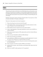
rounds of modification and testing before it fully satisfies your requirements. Figure 7-1 shows a
flowchart about using AutoQoS, verifying its auto-generated commands, and modifying the auto-
generated commands if necessary.
1763fm.book Page 220 Monday, April 23, 2007 8:58 AM
AutoQoS Shortcomings and Remedies 221
Figure 7-1 Verifying and Modifying AutoQoS-Generated Configurations
The procedure for modifying an existing, active classification or policy that AutoQoS generates
can be summarized into a three-step process:
Step 1 Review the existing QoS policy, identify the new requirements, and outline
the configuration modifications necessary.
Step 2 Modify the AutoQoS-generated configuration according to the new
requirements.
Step 3 Review the new (modified) configuration.
Please note that if you modify the AutoQoS-generated configuration, the AutoQoS generated
commands will not be removed properly when you enter the no auto qos command. The no auto
qos command only removes the original (unmodified) commands that AutoQoS generated.
OK?
Keep the Configuration,
But Monitor Network and
Traffic Condition Changes
View the Generated
Class Maps and
Policy Maps
Enable AutoQoS
(Generate Templates)
Start AutoQoS
Discovery
Let Autodiscovery Run
for Longer Period
Modify the AutoQos-
Generated Configuration
(Manually or Using QPM)
Examine Autodiscovery
Results While in Progress
Traffic or
Network Conditions
Changed?
Modify or
Start Over?
Yes
Yes
No
OK?
Yes
No
No
Autodiscovery Results
Do Not Meet Expectations
Autodiscovery Results
Do Not Meet Expectations
Start
Over
Modify
1763fm.book Page 221 Monday, April 23, 2007 8:58 AM
222 Chapter 7: Implementing AutoQoS
Foundation Summary
The “Foundation Summary” is a collection of information that provides a convenient review of
many key concepts in this chapter. If you are already comfortable with the topics in this chapter,
this summary can help you recall a few details. If you just read this chapter, this review should help
solidify some key facts. If you are doing your final preparation before the exam, the information in
this section is a convenient way to review the day before the exam.
Cisco AutoQoS is an automation tool for deploying QoS policies. Following are the key benefits
of Cisco AutoQoS:
■ Uses Cisco IOS built-in intelligence to automate generation of QoS configurations for most
common business scenarios
■ Protects business-critical data applications in the Enterprise to maximize their availability
■ Simplifies QoS deployment
■ Reduces configuration errors
■ Makes QoS deployment cheaper, faster, and simpler
■ Follows the DiffServ model
■ Allows customers to have complete control over their QoS configuration
■ Enables customers to modify and tune the configurations that Cisco AutoQoS automatically
generates to meet their specific needs or changes in the network conditions
The two phases of Cisco AutoQoS evolution are as follows:
1. AutoQoS VoIP
This was the first phase of AutoQoS.
One command provisions the basic required QoS commands.
It is supported across a broad range of router and switch platforms.
2. AutoQoS for Enterprise
This is the second phase of AutoQoS.
It extends the AutoQoS capabilities for data, voice, and video.
It is, however, supported only on routers.
1763fm.book Page 222 Monday, April 23, 2007 8:58 AM
Foundation Summary 223
It is deployed in a two-step process. In the first step, called autodiscovery, it discovers
the traffic types and loads using NBAR protocol discovery. In the second step, it
generates and implements QoS policies.
Cisco AutoQoS addresses five key elements of QoS deployment:
■ Application classification
■ Policy generation
■ Configuration
■ Monitoring and reporting
■ Consistency
AutoQoS for Enterprise uses NBAR protocol discovery. NBAR protocol discovery analyzes traffic
in real-time, identifies approximately 100 Layer 4 through 7 applications and protocols using
stateful and deep packet inspection, and provides bidirectional, per-interface, and per-protocol
statistics. NBAR protocol discovery is able to identify and classify all of the following application
types:
■ Applications that target a session to a well-known (UDP/TCP) destination port number,
referred to as static port applications
■ Applications that start a control session using a well-known port number but negotiate another
port number for the session, referred to as dynamic port applications
■ Some non-IP applications
■ HTTP applications based on URL, MIME type, or host name
You can enable Cisco AutoQoS Enterprise on certain types of interfaces and permanent virtual
circuits (PVCs) only. These are the interface and PVC types that you can enable AutoQoS
Enterprise for on a Cisco router:
■ Serial interfaces with PPP or HDLC encapsulation.
■ Frame Relay point-to-point subinterfaces. (Multipoint is not supported.)
■ ATM point-to-point subinterfaces (PVCs) on both slow (<=768 kbps) and fast serial (>768
kbps) interfaces.
■ Frame Relay-to-ATM interworking links.
1763fm.book Page 223 Monday, April 23, 2007 8:58 AM
224 Chapter 7: Implementing AutoQoS
Following are the router prerequisites for configuring Cisco AutoQoS:
■ The router cannot have a QoS policy attached to the interface.
■ You must enable CEF on the router interface (or PVC).
■ You must specify the correct bandwidth on the interface or subinterface.
■ You must configure a low-speed interface (<= 768 Kbps) and an IP address.
You deploy AutoQoS for Enterprise on Cisco routers in two steps (or two phases):
Step 1 Traffic is profiled using autodiscovery.
You do this by entering the auto qos discovery command in the interface
configuration mode.
Step 2 MQC-based QoS policies are generated and deployed.
You do this by entering the auto qos command in interface configuration
mode.
On Cisco LAN switches, AutoQoS VoIP is enabled on each interface using the auto qos voip
[trust | cisco-phone] command. The trust keyword is used for trusted connections such as an
uplink to a trusted switch or router so that the ingress VoIP packet marking is trusted. You use the
cisco-phone keyword for Cisco IP phone connections and to enable the trusted boundary feature.
You use CDP to detect the presence or absence of a Cisco IP phone.
The commands for verifying Cisco AutoQoS on routers are as follows:
■ show auto discovery qos
Allows you to examine autodiscovery results
■ show auto qos
Allows you to examine Cisco AutoQoS templates and initial configuration
■ show policy-map interface
Allows you to explore interface statistics for autogenerated policy
The commands for verifying Cisco AutoQoS on Cisco LAN switches are as follows:
■ show auto qos
Allows you to examine Cisco AutoQoS templates and initial configuration
1763fm.book Page 224 Monday, April 23, 2007 8:58 AM
Foundation Summary 225
■ show policy-map interface
Allows you to explore interface statistics for autogenerated policy
■ show mls qos maps
Allows you to examine CoS-to-DSCP maps
The three most common Cisco AutoQoS issues that might arise, and their corresponding solutions,
are as follows:
■ Too many traffic classes are generated; classification is overengineered.
Solution: Manually consolidate similar classes to produce the number of classes
needed.
■ The configuration that AutoQoS generates does not automatically adapt to changing network
traffic conditions.
Solution: Run Cisco AutoQoS discovery on a periodic basis, followed by re-
enabling of Cisco AutoQoS.
■ The configuration that AutoQoS generates fits common network scenarios but does not fit
some circumstances, even after extensive autodiscovery
Solution: Manually fine-tune the AutoQoS-generated configuration.
You examine the AutoQoS-generated configuration using the show auto qos command, which
provides the following information:
■ Number of traffic classes identified (class maps)
■ Traffic classification options selected (within class maps)
■ Traffic marking options selected (within policy maps)
■ Queuing mechanisms deployed and their corresponding parameters (within policy maps)
■ Other QoS mechanisms deployed (within policy maps)
■ Where the autogenerated policies are applied: on the interface, subinterface, or PVC
You might have to modify the configuration that AutoQoS generates for two reasons:
■ The AutoQoS-generated commands do not completely satisfy the specific requirements of the
Enterprise network.
■ The network condition, policies, traffic volume and patterns, and so on might change over
time, rendering the AutoQoS-generated configuration dissatisfying.
1763fm.book Page 225 Monday, April 23, 2007 8:58 AM
226 Chapter 7: Implementing AutoQoS
You can modify and tune the AutoQoS-generated class maps and policy maps by doing the
following:
■ Using Cisco QoS Policy Manager (QPM).
■ Directly entering the commands one at a time at the router command-line interface using
MQC.
■ Copying the existing configuration, a class map for example, into a text editor and modifying
the configuration using the text editor offline. Next, using CLI, remove the old undesirable
configuration and then add the new configuration by copying and pasting the text from the
text editor. This is probably the easiest way.
For classification purposes, in addition to using NBAR and ACLs, you can use the following
classification options that MQC offers for tuning:
■ Based on the specific ingress interface where the traffic comes from:
mm
mm
aa
aa
tt
tt
cc
cc
hh
hh
ii
ii
nn
nn
pp
pp
uu
uu
tt
tt
ii
ii
nn
nn
tt
tt
ee
ee
rr
rr
ff
ff
aa
aa
cc
cc
ee
ee
interface
■ Based on the Layer 2 CoS value of the traffic:
mm
mm
aa
aa
tt
tt
cc
cc
hh
hh
cc
cc
oo
oo
ss
ss
cos-value
[
cos-value
]
■ Based on the Layer 3 IP precedence value:
mm
mm
aa
aa
tt
tt
cc
cc
hh
hh
ii
ii
pp
pp
pp
pp
rr
rr
ee
ee
cc
cc
ee
ee
dd
dd
ee
ee
nn
nn
cc
cc
ee
ee
ip-prec-value
[
ip-prec-value
]
■ Based on the Layer 3 IP DSCP value:
mm
mm
aa
aa
tt
tt
cc
cc
hh
hh
ii
ii
pp
pp
dd
dd
ss
ss
cc
cc
pp
pp
ip-dscp-value
[
ip-dscp-value
]
■ Based on the RTP port value range:
mm
mm
aa
aa
tt
tt
cc
cc
hh
hh
ii
ii
pp
pp
rr
rr
tt
tt
pp
pp
starting-port-number
port-range
1763fm.book Page 226 Monday, April 23, 2007 8:58 AM
Q&A 227
Q&A
Some of the questions that follow challenge you more than the exam by using an open-ended
question format. By reviewing now with this more difficult question format, you can exercise your
memory better and prove your conceptual and factual knowledge of this chapter. The answers to
these questions appear in Appendix A.
1. List at least three key benefits of Cisco AutoQoS.
2. What are the two phases of AutoQoS evolution?
3. What are the five key elements of QoS deployment that Cisco AutoQoS addresses?
4. Which application types is NBAR protocol discovery able to identify and classify?
5. On what types of router interfaces or PVCs can you enable Cisco AutoQoS?
6. What are the router prerequisites for configuring AutoQoS?
7. What are the two steps (or phases) of AutoQoS for Enterprise?
8. List at least two commands for verifying AutoQoS on Cisco routers.
9. List at least two commands for verifying AutoQoS on Cisco LAN switches.
10. What are the three most common Cisco AutoQoS issues that can arise, and their
corresponding solutions?
11. List at least three pieces of information that can be obtained from the output of the show auto
qos command.
12. What are the two major reasons for modifying the configuration that AutoQoS generates?
13. Specify two methods for modifying and tuning the AutoQoS-generated class maps and policy
maps.
14. In addition to using NBAR and ACLs, what classification options does MQC offer?
1763fm.book Page 227 Monday, April 23, 2007 8:58 AM
This part covers the following ONT exam topics. (To view the ONT exam
overview, visit />642-845.html.)
■ Describe and configure WLAN QoS.
■ Describe and configure wireless security on Cisco Clients and APs (e.g.,
SSID, WEP, LEAP, etc.).
■ Describe basic wireless management (e.g., WLSE and WCS). Configure and
verify basic WCS configuration (i.e., login, add/review controller/AP status,
security, and import/review maps).
1763fm.book Page 228 Monday, April 23, 2007 8:58 AM
Part III: Wireless LAN
Chapter 8 Wireless LAN QoS Implementation
Chapter 9 Introducing 802.1x and Configuring Encryption and
Authentication on Lightweight Access Points
Chapter 10 WLAN Management
1763fm.book Page 229 Monday, April 23, 2007 8:58 AM
This chapter covers the
following subjects:
■ The Need for Wireless LAN QoS
■ Current Wireless LAN QoS
Implementation
■ Configuring Wireless LAN QoS
1763fm.book Page 230 Monday, April 23, 2007 8:58 AM
C H A P T E R
8
Wireless LAN QoS
Implementation
This chapter first describes WLAN QoS and why it is needed. Next, it covers the current
implementation of WLAN QoS. The last section describes how to configure WLAN QoS for
different QoS profiles using the Cisco WCS web user interface.
“Do I Know This Already?” Quiz
The purpose of the “Do I Know This Already?” quiz is to help you decide whether you really
need to read the entire chapter. The 10-question quiz, derived from the major sections of this
chapter, helps you determine how to spend your limited study time.
Table 8-1 outlines the major topics discussed in this chapter and the “Do I Know This Already?”
quiz questions that correspond to those topics. You can keep track of your score here, too.
Table 8-1 “Do I Know This Already?” Foundation Topics Section-to-Question Mapping
Foundation Topics Section Covering These Questions Questions Score
“The Need for Wireless LAN QoS” 1–6
“Current Wireless LAN QoS Implementation” 7–8
“Configuring Wireless LAN QoS” 9–10
Total Score (10 possible)
CAUTION The goal of self-assessment is to gauge your mastery of the topics in this
chapter. If you do not know the answer to a question or are only partially sure of the answer,
mark this question wrong for purposes of the self-assessment. Giving yourself credit for an
answer you correctly guess skews your self-assessment results and might provide you with a
false sense of security.
1763fm.book Page 231 Monday, April 23, 2007 8:58 AM
232 Chapter 8: Wireless LAN QoS Implementation
You can find the answers to the “Do I Know This Already?” quiz in Appendix A, “Answers to the
‘Do I Know This Already?’ Quizzes and Q&A Sections.” The suggested choices for your next step
are as follows:
■ 6 or less overall score—Read the entire chapter. This includes the “Foundation Topics,”
“Foundation Summary,” and “Q&A” sections.
■ 7–8 overall score—Begin with the “Foundation Summary” section and then follow up with
the “Q&A” section at the end of the chapter.
■ 9 or more overall score—If you want more review on this topic, skip to the “Foundation
Summary” section and then go to the “Q&A” section. Otherwise, proceed to the next chapter.
1. Select the correct statement about wireless LANs.
a. WLANs are mostly implemented as extensions to wired LANS.
b. WLANs are occasionally implemented as overlays to wired LANs.
c. WLANs are sometimes implemented as substitutes for wired LANs.
d. All of the above.
2. Which statement is true about 802.11 wireless media access control?
a. It uses CSMA/CD.
b. It uses token passing.
c. It uses CSMA/CA.
d. All of the above.
3. Distributed coordinated function (DCF) performs collision avoidance using which of these?
a. Radio frequency (RF) carrier sense
b. Interframe spacing (IFS)
c. Random back-off/contention windows (CW)
d. All of the above
4. IEEE provides QoS extensions to wireless LANs by which of the following drafts/standards?
a. 802.11g
b. 802.11e
c. 802.11d
d. 802.11a
1763fm.book Page 232 Monday, April 23, 2007 8:58 AM
“Do I Know This Already?” Quiz 233
5.
Select the item that is not a real-time function performed by the access point in the Split-MAC
architecture.
a. Key management
b. Beacon generation
c. Probe transmission
d. Encryption/decryption
6. Which of the following shows the correct mapping of 802.11e priority levels to WMM access
categories?
a. Voice(Platinum)=6/7, Video(Gold)=4/5, Best-Effort(Silver)=1/2, Back-
ground(Bronze)=0/3
b. Voice(Platinum)=6/7, Video(Gold)=4/5, Best-Effort(Silver)=3/2, Back-
ground(Bronze)=0/1
c. Voice(Platinum)=6/7, Video(Gold)=4/5, Best-Effort(Silver)=0/3, Back-
ground(Bronze)=1/2
d. None of the above
7. Select the correct statement about how wireless LAN controller copies/maps QoS fields in the
Split-MAC architecture.
a. Wireless LAN controller copies the IP DSCP field (inner) to the DSCP field (outer) of
the LWAPP data unit.
b. Wireless LAN controller maps the IP DSCP field (inner) to the 802.1p field (outer) of
the LWAPP data unit.
c. Wireless LAN controller maps the DSCP field from the LWAPP data unit to the 802.1p
field on the 802.1Q frame.
d. All of the above.
8. Which priority (802.1p) value is used/reserved for LWAPP control messages?
a. 6
b. 7
c. 0
d. 1
1763fm.book Page 233 Monday, April 23, 2007 8:58 AM
234 Chapter 8: Wireless LAN QoS Implementation
9.
Which of the following is not a parameter set in the Edit QoS Profile page of the Web User
Interface for Wireless LAN Controller, as a part of Per-User Bandwidth Contract?
a. Average voice rate
b. Average data rate
c. Burst data rate
d. Burst real-time rate
10. On the WLANs > Edit page of the web user interface of the wireless LAN controller, what
does it mean if the general WMM or 802.11e policy for the interaction between the wireless
client and the access point is set to Required?
a. This setting means that WMM or 802.11e QoS requests are ignored.
b. This setting means that QoS is offered to WMM or 802.11e-capable clients.
c. This setting means that all clients must be WMM/802.11e compliant to use this
WLAN ID.
d. None of the above is correct.
1763fm.book Page 234 Monday, April 23, 2007 8:58 AM
The Need for Wireless LAN QoS 235
Foundation Topics
The Need for Wireless LAN QoS
WLANs are growing in popularity. They are mostly implemented as extensions to, but are occasionally
deployed as overlays to, wired LANs, or replacements for wired LANs. The difference between
wired and wireless LANs is in the physical layer and in the MAC layer. Please note that Logical
Link Control (LLC) and MAC are considered upper and lower sublayers of the OSI Layer 2 Data
Link Control (DLC) layer, respectively. Upper-layer protocols and applications such as IP, TCP,
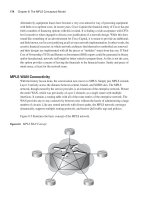
and FTP run identically on both wired and wireless platforms. Figure 8-1 shows two access
switches (Layer 2) connected to a distribution (multilayer) switch. The access switch on the right
side has wired devices plugged into its access ports. The access switch on the left side, however,
is connected to a wireless LAN controller (WLC), which in turn is connected to and controls two
wireless LAN APs. Each wireless client on the left side of Figure 8-1 communicates with an AP
by sending and receiving frames over the radio frequency (RF) link, and it gains access to the
network.
1763fm.book Page 235 Monday, April 23, 2007 8:58 AM
236 Chapter 8: Wireless LAN QoS Implementation
Figure 8-1 Wireless LAN Extending the Wired LAN
Wired Ethernet uses carrier sense multiple access with collision detection (CSMA/CD) as its
MAC mechanism. Wireless LAN (802.11), on the other hand, lacks the ability to read and send
data at the same time; therefore, it cannot detect collision like its wired counterpart can. Hence,
WLAN uses carrier sense multiple access with collision avoidance (CSMA/CA) as the MAC
mechanism. Collision avoidance is accomplished by distributed coordinated function (DCF). DCF
uses RF carrier sense, inter-frame spacing (IFS), and random back-off/CWs. Please note that
random back-off/CWs are sometimes casually referred to as random wait timers.
Wireless LAN
Controller (WLC)
Layer 2/3
Network
Wireless
Access Points
(AP)
Wireless
Clients
1763fm.book Page 236 Monday, April 23, 2007 8:58 AM
The Need for Wireless LAN QoS 237
To be able to offer end-to-end QoS, the wireless portion and components of a network must
comply with and satisfy the QoS needs of the applications. Following are some of the main QoS
needs of applications, such as voice and video:
■ Dedicated bandwidth
■ Controlled jitter and delay (latency)
■ Managed congestion
■ Shaped traffic (rate limited)
■ Prioritized traffic (with drop preference)
WLAN QoS Description
IEEE has provided the QoS extensions to WLANs in the 802.11e specifications. The ONT
courseware refers to 802.11e as a draft for standardization, but at the time of this writing, 802.11e
is already approved and is considered a new standard. IEEE defines 802.11e as the first wireless
standard, adding QoS features to the existing IEEE 802.11b and IEEE 802.11a (and other)
wireless standards, while maintaining full backward compatibility with them. While 802.11e was
in the standardization process, Wi-Fi Alliance released a specification called the Wi-Fi Multimedia
(WMM) for the interim period.
WMM is a subset of 802.11e; for instance, WMM reduces the eight priority levels of 802.11e to
four access categories. Note that access category has the same meaning as priority level. Using the
basic CSMA/CA-based DCF, each client generates a random back-off number between 0 and a
minimum contention window (CW
min
) and waits until the RF channel is free for an interval called
distributed coordinated function inter-frame space (DCF IFS or DIFS). From that moment on, the
channel is continuously checked; if it is free, the random back-off number is decremented by 1
until it becomes 0. At that time, the client sends the frame. If the channel becomes busy, the client
has to wait until the channel is free, wait for a DIFS interval, and start decrementing the random
back-off interval all over again.
The CSMA/CA-based DCF gives all devices the same priority, so it is considered a best-effort
mechanism. WMM, on the other hand, provides traffic prioritization (or RF prioritization) by
using four access categories: Platinum (or voice), Gold (or video), Silver (best-effort), and Bronze
(background), in descending priority order. The four access categories are in effect four queues,
each of which gets a higher probability of transmitting than the access priority (or queue) below
it. If a specific type of traffic is not assigned to an access category, it is categorized as best-effort
(Silver). The eight 802.11e priority levels are mapped to four WMM access categories, as shown
in Table 8-2.
1763fm.book Page 237 Monday, April 23, 2007 8:58 AM
238 Chapter 8: Wireless LAN QoS Implementation
802.11e (and its subset WMM) uses Enhanced Distributed Coordination Function (EDCF) by
employing different CW/back-off timer values for different priorities (access categories). If a
client finds the RF channel available, it waits for a DIFS period, and then it has to wait for a
random back-off period based on the CW
min
associated with the priority of the traffic being
submitted (more accurately, the queue that the traffic is submitted from). If the traffic is high
priority, its CW
min
is smaller, giving it a shorter back-off timer value; if the traffic is lower priority,
its CW
min
is larger, giving it a longer back-off timer value. Note that with EDCF, even though
high-priority traffic such as voice is statistically expected to be transmitted before lower-priority
traffic, it is not guaranteed to do so at all times; therefore, technically EDCF cannot be equated to
a strict priority system. With EDCF, IFS (Inter Frame Space) is referred to as AIFS (Arbitrated
IFS).
Split MAC Architecture and Light Weight Access Point
To centralize the security, deployment, management, and control aspects of WLANs, Split MAC
Architecture (a part of Cisco Unified Wireless Network Architecture) shifts some of the functions
traditionally performed on the autonomous AP to a central location (device). The main functions
performed on legacy autonomous APs are shown in Table 8-3 categorized under two columns:
real-time 802.11/MAC functionality, and non-real-time 802.11/MAC functionality.
Table 8-2 Mapping of 802.11e Priority Levels to WMM Access Categories
WMM Access Category 802.11e Priority Level
Voice (Platinum) 6 or 7
Video (Gold) 4 or 5
Best-Effort (Silver) 0 or 3
Background (Bronze) 1 or 2
NOTE In the original ONT student course material, on the page titled “WLAN QoS RF Back-
Off Timing,” SIFS is mistakenly used instead of DIFS. Short inter-frame space (SIFS) is used
only before transmitting important frames such as acknowledgements, and it has no random
back-off. SIFS is not used to transmit regular data frames. Data frames, on the other hand, must
wait for a DIFS and then begin the random back-off procedure.
Table 8-3 Real-Time and Non-Real-Time 802.11 MAC Functions
802.11/MAC Real-Time Functions 802.11/MAC Non-Real-Time Functions
Beacon generation Association/disassociation/reassociation
Probe transmission and response 802.11e/WMM resource reservation
Power management 802.1x EAP
1763fm.book Page 238 Monday, April 23, 2007 8:58 AM