CCNA Self-Study CCNA INTRO Exam Certification Guide phần 9 potx
Bạn đang xem bản rút gọn của tài liệu. Xem và tải ngay bản đầy đủ của tài liệu tại đây (1.6 MB, 62 trang )
462 Chapter 15: Remote Access Technologies
from the drop cable and passes it out both of the other lines. Note that the connector, the
round connector common on most CATV cabling, is called an f-connector.
When using a cable modem, the CATV company becomes your ISP. Everything between your
house and the router at the head end is a single physical and data link. The PC in your home
uses a router owned by the cable company, housed at the head-end site, as its default
gateway. In fact, the PC typically uses DHCP to discover its IP address and the IP address of
its default gateway; the DHCP server would be inside the cable company’s IP network,
typically at the head-end site.
Conceptually, what happens between the home and the cable head end is similar to a single
LAN segment. The details, of course, are different, but the cable installation provides a
combination of Layer 1 and Layer 2 protocols to let a PC deliver IP packets to a router inside
the cable network. So, as you read about the details of what happens between the home and
the router at the head end, keep in mind that the goal is simply to deliver IP packets between
the home and the head-end router, and vice versa.
Layer 1 and Layer 2 between the Home and the Head End
Cable TV systems originally were built to send TV video and audio signals to lots of places,
with no need to receive a signal back. In other words, the idea of having someone’s TV send
some information back to the cable company was not even under consideration. Because the
original CATV architecture allowed for sending signals from the head end outward, and the
capability for two-way communication was added later, data over cable standards treats data
going toward the home differently than data coming from the home. In fact, CATV
terminology refers to the data going toward the home as downstream data, and data from
the home as upstream data.
Downstream data uses standards that are consistent with some of the standards for sending
digital video over cable. In fact, you can think of the downstream data as being sent over
another TV channel. For downstream data, the data over cable standards takes advantage of
the fact that the signals are broadcast to all subscribers in a section of the cable plant. Just
like the TV channels’ signals go to every home, the signals for the downstream data go to
every home. In many ways, the concepts are similar to an Ethernet broadcast domain: When
a broadcast Ethernet frame is sent, everyone in the broadcast domain receives the frame.
With downstream cable transmissions, not just broadcast frames, but all data, is broadcast
to all receivers. Yes, the data that you receive over the web actually could be captured with
a network analysis tool by one of your neighbors.
Because every home in a part of the cable network receives the same data channel, some form
of addresses must be used so that only the correct device tries to process incoming data. For
0945_01f.book Page 462 Wednesday, July 2, 2003 3:53 PM
Cable Modems 463
instance, your PC does not need to process any data being sent to your neighbor’s PC. So,
CATV standards call for the use of a data-link protocol called Multimedia Cable Network
Systems (MCNS) MAC. (You might remember that MAC stands for Media Access Control.)
MCNS is similar to Ethernet’s MAC, as defined in the IEEE 802.3 specification, including the
use of Ethernet MAC addresses. So, although all downstream data is sent to all drops in the
cable system, only those with a cable modem know that data has been received, and only the
PCs with the correct MAC address process the data.
MCNS also defines the physical encoding details. MCNS calls for the use of a modulation
method called quadrature amplitude modulation (QAM). Two options can be used for
downstream data, one called QAM-64 and the other called QAM-256. QAM-64 represents
6 bits per baud, and QAM-256 represents 8 bits per baud.
Table 15-6 summarizes some of the key reference information about downstream data over
cable.
Upstream Data
The upstream data channel uses a totally separate frequency range than the downstream
channel, so no collisions occur between downstream and upstream data. However, all
upstream data from multiple cable subscribers does share the same frequency range—the
same channel, essentially—so collisions can occur between data sent toward the Internet by
the different home users.
Noticing that a collision has occurred in an upstream cable channel is much more difficult
than with an Ethernet. Cables inside the CATV cable plant might be miles long, which means
that a device would have to wait longer for the electrical signal from a collision to return. So,
the CSMA/CD algorithm used by Ethernet does not work well on the upstream channel.
Instead, MCNS defines the use of a multiplexing method called time-division multiple access
(TDMA), in which each home user is granted regular time periods during which to send
upstream data. These time slots happen multiple times per second. By using TDMA, most
collisions can be avoided.
Table 15-6 Downstream Data over Cable: Interesting Facts
Downstream Rate
OSI Layer 1 QAM-64 and QAM-256 encoding
OSI Layer 2 MCNS MAC and IEEE 802.2 LLC
Multiplexing used Frequency-division multiplexing
Speed 30 to 40 Mbps
0945_01f.book Page 463 Wednesday, July 2, 2003 3:53 PM
464 Chapter 15: Remote Access Technologies
The upstream channel uses the same data-link protocols as the downstream channel, with
MAC addressing, but it uses different modulation schemes. The upstream channel uses
quaternary phase-shift keying (QPSK) or QAM-16. QPSK modulates the signal using phase
shifts, while QAM uses amplitude modulation.
Both the downstream and upstream channels compete with other users for the use of the
channel. So, as more subscribers are added, the actual throughput of the connection actually
can slow down.
Table 15-7 summarizes some of the key points about the upstream data channel.
Cable Modem Summary
Like DSL, cable modems bring high-speed remote access capabilities to the home. The speeds
might seem astounding—30 to 40 Mbps downstream is indeed impressive. In fact, I had a
cable modem a few years ago and was one of the first people in my neighborhood to get it. I
surfed the web much faster from home than I did from the local Cisco Systems office! The
data service is always on, even when someone is watching TV. Because it doesn’t use the
telephone line at all, you also can use the phone at the same time.
Cable modems do have a few drawbacks. The per-user data rates degrade as more users are
added to the network. Also, because the network broadcasts all downstream traffic, anyone
can put a network-analysis tool in their home and get a copy of what their neighbor is
receiving.
Comparison of Remote Access Technologies
This chapter scratches the surface of how modems, ISDN, cable, and DSL work. Consumers
choose between these options for Internet access all the time, and network engineers choose
between these options for supporting their work-at-home users as well. So, it seems
appropriate to close the chapter by listing some of the key comparison points for these
options.
Table 15-7 Upstream Data over Cable: Interesting Facts
Downstream Rate
OSI Layer 1 QPSK and QAM-16
OSI Layer 2 MCNS MAC and IEEE 802.2 LLC
Multiplexing used Time-division multiple access (TDMA)
Speed 320 kbps to 10 Mbps
0945_01f.book Page 464 Wednesday, July 2, 2003 3:53 PM
Comparison of Remote Access Technologies 465
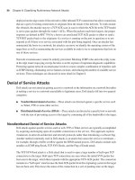
The remote access technologies in this chapter provide services at Layer 1, and possibly Layer
2, of the OSI reference model. TCP/IP and all the associated higher-layer protocols (TCP,
UDP, HTTP, FTP, Telnet, DNS, DHCP, and so on) can run over any of these access
technologies; the differences lie in what is done at Layers 1 and 2. Figure 15-16 outlines the
protocols used by each.
Figure 15-16 The OSI Reference Model and Remote Access Technologies
Table 15-8 lists some of the main points for comparison of these technologies.
Table 15-8 Comparison of Modems, ISDN, DSL, and Cable
Analog Modems ISDN DSL Cable Modems
Transport Telco line Telco line Telco line CATV cable
Supports symmetric
speeds?
Yes Yes Yes No
Supports asymmetric
speeds?
Yes No Yes Yes
Speed ranges 56 kbps and lower 64 kbps per
B channel
56 kbps to
2 Mbps
320 kbps to
40 Mbps
Applications
TCP or UDP
IP
PPP
Modem Standards
(v.x)
Applications
TCP or UDP
IP
PPP
ISDN (I-430)
Standards
Applications
TCP or UDP
IP
PPP
xDSL
Standards
ATM Ethernet
Applications
TCP or UDP
IP
IEEE 802.2
MCNS MAC
Upstream-
QPSK, QAM-16
Downstream-
QAM-64, QAM-256
continues
0945_01f.book Page 465 Wednesday, July 2, 2003 3:53 PM
466 Chapter 15: Remote Access Technologies
Analog Modems ISDN DSL Cable Modems
Degrades under higher
loads?
No No No Yes
Supports IP and
associated higher-layer
protocols?
Yes Yes Yes Yes
Allows concurrent
voice and data?
No Yes Yes Yes
Always on? No No Yes Yes
Local loop distance
issues
No No Yes; distance
varies
No
Table 15-8 Comparison of Modems, ISDN, DSL, and Cable (Continued)
0945_01f.book Page 466 Wednesday, July 2, 2003 3:53 PM
Foundation Summary 467
Foundation Summary
The “Foundation Summary” section of each chapter lists the most important facts from the
chapter. Although this section does not list every fact from the chapter that will be on your
CCNA exam, a well-prepared CCNA candidate should know, at a minimum, all the details
in each “Foundation Summary” section before going to take the exam.
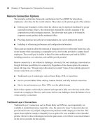
Figure 15-17 depicts the PSTN and how it supports analog voice through a digital T1 core.
Figure 15-17 Analog Voice Calls Through a Digital PSTN
Table 15-9 lists some of the key modem standards.
Table 15-9 Modem Standards
Standard Speed Comments
V.22 1200 bps (600 baud) Mainly used outside the United States
V.22bis* 2400 bps (600 baud) First widely deployed worldwide
standard
V.32 4800/9600 (2400 baud) Adjusts speed based on line quality
V.32bis* 14.4kbps (2400 baud) Backward compatible with V.32
Local
Loop
(Analog)
Local
Loop
(Analog)
Digital T1 Line
(24 separate
64Kbps DS0
Channels)
PCM Codec Converts
Analog Digital
PCM Codec Converts
Analog Digital
Telco Voice
Switch
Raleigh CO
Telco Voice
Switch
Mayberry CO
Barney’s
phone
Andy’s
phone
PSTN
continues
0945_01f.book Page 467 Wednesday, July 2, 2003 3:53 PM
468 Chapter 15: Remote Access Technologies
*“bis” simply means “version 2.”
Figure 15-18 shows the typical topology with ISDN in use for access to an ISP.
Figure 15-18 ISDN Local Loops and Equipment
Table 15-10 lists the number of channels for each type of ISDN line and the terminology used
to describe them.
Standard Speed Comments
V.34 28.8 kbps Backward compatible with V.32bis and
V.32
V.42 28.8 kbps Same speed as V.34, but with error-
correction features
V.90 56 kbps (downstream), 33 kbps
(upstream)
Created from two earlier competing
standards, X2 and K56Flex
V.92 56 kbps/33 kbps (downstream/
upstream) or 48 kbps (each direction)
Connects and finds correct speed more
quickly than V.90; allows “modem-on-
hold”
Table 15-10 BRI and PRI B and D Channels
Type of
Interface
Number of Bearer
Channels (B Channels)
Number of Signaling
Channels (D Channels) Descriptive Term
BRI 2 1 (16 kbps) 2B+D
PRI (T1) 23 1 (64 kbps) 23B+D
PRI (E1) 30 1 (64 kbps) 30B+D
Table 15-9 Modem Standards (Continued)
Local Loop
(Digital BRI)
Local Loop
(Digital PRI)
Digital T1 Line
(1 DS0 Channel
used)
No PCM Needed on Andy’s
Digital Local Loop
No PCM Needed – No
Analog Signal!
Telco
ISDN
Switch
Raleigh CO
Internal
ISDN
Card
Telco
ISDN
Switch
Mayberry CO
PSTN
R3
RS-232
Cable
Andy’s
PC
0945_01f.book Page 468 Wednesday, July 2, 2003 3:53 PM
Foundation Summary 469
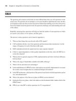
Figure 15-19 shows some of the detail of a typical DSL connection.
Figure 15-19 DSL Connection from the Home
Table 15-11 lists the major DSL variants, the standard defining that variant, the modulation/
encoding technique, speed, and distance limitations.
Table 15-11 DSL Technologies Standards Comparison
DSL Type Standards
Modulation/Encoding
Technique Speed
Distance
Limit
Full-rate
ADSL/G.DMT
ANSI T1.413
Issue 2
Discrete multitone (DMT)
or carrierless amplitude
phase (CAP)
Downstream speed of 384
to 8 Mbps; upstream speed
slower, up to 1.024 Mbps
18,000 feet
G.Lite ITU-T G.992.1,
ITU-T G.992.2
DMT Downstream speed up to
1.544 Mbps to 6 Mbps;
upstream speed up to 640
kbps
18,000 feet
Voice Switch w/PC
DSL
Router/
Modem
Ethernet
Andy’s
Analog
phone
Andy’s
PC
DTMF Tones,
Analog Voice,
0 – 4000 Hz
Digital
Signals >
4000 Hz
Analog Voice
Split to Voice
Switch
Andy’s House Mayberry CO
Local Loop
DSLAM
IP Traffic
Split to ISP
Router
IP Network
Owned by ISP
PSTN
continues
0945_01f.book Page 469 Wednesday, July 2, 2003 3:53 PM
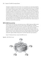
470 Chapter 15: Remote Access Technologies
Figure 15-20 outlines some of the key terms used with CATV.
DSL Type Standards
Modulation/Encoding
Technique Speed
Distance
Limit
Very-high-
data-rate DSL
(VDSL)
ETSI and ANSI
in process
DMT/single-carrier
modulation (SCM)
12.96 Mbps to 52.8 Mbps
for both upstream and
downstream speed
4500 feet
ISDN DSL
(IDSL)
ANSI ETR 080 Two binary one quaternary
(2B1Q)
144 kbps for both
upstream and downstream
speed
18,000 feet
Symmetric
DSL (SDSL)
None 2B1Q 768 kbps for both
upstream and downstream
speed
22,000 feet
High-data-rate
DSL (HDSL
ITU G.991.1,
ANSI TR 28
2B1Q 1.544 or 2.048 Mbps for
both upstream and
downstream speed
12,000 feet
G.SHDSL ITU G.991.2 Trellis-coded pulse
amplitude modulation
(TC PAM)
192 kbps to 2.360 Mbps
for both upstream and
downstream speed
28,000 feet
Table 15-11 DSL Technologies Standards Comparison (Continued)
0945_01f.book Page 470 Wednesday, July 2, 2003 3:53 PM
Foundation Summary 471
Figure 15-20 Cable TV Terminology
Table 15-12 summarizes some of the key reference information about downstream CATV
data over cable.
Table 15-12 Downstream Data over Cable: Interesting Facts
Downstream Rate
OSI Layer 1 QAM-64 and QAM-256 encoding
OSI Layer 2 MCNS MAC and IEEE 802.2 LLC
Multiplexing used Frequency-division multiplexing
Speed 30 to 40 Mbps
Ethernet
F-connectors
Head-end
Andy’s House
Mayberry CATV
Drop Cable
Distribution Cables
Andy’s
PC
Spilt
Cable Modem
0945_01f.book Page 471 Wednesday, July 2, 2003 3:53 PM
472 Chapter 15: Remote Access Technologies
Table 15-13 summarizes some of the key points about the upstream CATV data channel.
The remote access technologies in this chapter provide services at Layer 1, and possibly Layer 2,
of the OSI model. TCP/IP and all the associated higher-layer protocols (TCP, UDP, HTTP, FTP,
Telnet, DNS, DHCP, and so on) can run over any of these access technologies; the differences lie
in what is done at Layers 1 and 2. Figure 15-21 outlines the protocols used by each.
Figure 15-21 The OSI Model and Remote Access Technologies
Table 15-13 Upstream Data over Cable: Interesting Facts
Downstream Rate
OSI Layer 1 QPSK and QAM-16
OSI Layer 2 MCNS MAC and IEEE 802.2 LLC
Multiplexing used Time-division multiple access (TDMA)
Speed 320 kbps to 10 Mbps
Applications
TCP or UDP
IP
PPP
Modem Standards
(v.x)
Applications
TCP or UDP
IP
PPP
ISDN (I-430)
Standards
Applications
TCP or UDP
IP
PPP
xDSL
Standards
ATM Ethernet
Applications
TCP or UDP
IP
IEEE 802.2
MCNS MAC
Upstream-
QPSK, QAM-16
Downstream-
QAM-64, QAM-256
0945_01f.book Page 472 Wednesday, July 2, 2003 3:53 PM
Foundation Summary 473
Table 15-14 lists some of the main points for comparison of these technologies. Comparison
points are always good material for exam questions.
Table 15-14 Comparison of Modems, ISDN, DSL, and Cable
Analog Modems ISDN DSL Cable Modems
Transport Telco line Telco line Telco line CATV cable
Supports symetric
speeds?
Yes Yes Yes No
Supports asymmetric
speeds?
Yes No Yes Yes
Speed ranges Less than
56 kbps
64 kbps per
B channel
56 kbps to
2 Mbps
320 kbps to 40
Mbps
Degrades under higher
loads?
No No No Yes
Supports IP and
associated higher-layer
protocols?
Yes Yes Yes Yes
Allows concurrent
voice and data?
No Yes Yes Yes
Always on? No No Yes Yes
Local loop distance
issues
No No Yes; distance
varies
No
0945_01f.book Page 473 Wednesday, July 2, 2003 3:53 PM
474 Chapter 15: Remote Access Technologies
Q&A
As mentioned in the introduction, you have two choices for review questions. The questions
that follow give you a bigger challenge than the exam itself by using an open-ended question
format. By reviewing now with this more difficult question format, you can exercise your
memory better and prove your conceptual and factual knowledge of this chapter. The
answers to these questions are found in Appendix A.
For more practice with exam-like question formats, including questions using a router
simulator and multiple-choice questions, use the exam engine on the CD.
1. What do ISDN, BRI, and PRI stand for?
2. How many bearer channels are in a BRI? What about a PRI in North America? What
about a PRI in Europe?
3. Define what a voice codec does, and explain why a PCM codec needs 64 kbps for a single
voice call.
4. Two terms were shortened and combined to first create the word modem. Identify those
two words and describe what each word means.
5. Define what the terms symmetric and asymmetric mean in relation to modem
specifications. Also explain why asymmetric might be a better option.
6. Compare the V.90 and V.92 modem specifications.
7. Compare analog modems, ISDN BRIs, DSL, and cable modems in terms of concurrent
support for voice and data.
8. Compare analog modems, ISDN BRIs, DSL, and cable modems in terms of whether the
data service is always on.
9. List some of the pros and cons regarding the use of analog modems for remote access.
10. List some of the pros and cons regarding the use of ISDN for remote access.
11. List some of the pros and cons regarding the use of DSL for remote access.
12. Define what the acronym DSLAM stands for, and explain the concept behind how a
DSLAM allows voice and data to flow over the same local loop phone line.
13. Which of the DSL standards is the most common in the United States today? What is the
range of upstream and downstream speeds for that type of DSL, as well as the maximum
distance of the local loop?
0945_01f.book Page 474 Wednesday, July 2, 2003 3:53 PM
Q&A 475
14.
What protocols are used by DSL at the data link layer?
15. Imagine that Andy and Barney are neighbors, and they both use cable modems. Describe
the type of traffic that they could generate that could cause collisions, and tell what is
done to help prevent those collisions.
16. Name the four different Layer 1 encoding methods defined for use by cable modems. For
each one, list whether it is used for upstream data, downstream data, or both.
17. Which of the four different remote access technologies support IP, TCP, UDP, and the rest
of the higher-layer TCP/IP protocols?
18. Compare and contrast the cabling used by an analog modem and a DSL router/modem
when connecting to the local phone company line. Identify the purpose of each pin on
the connector.
19. Compare and contrast the cabling used by an ISDN modem and a cable modem when
connecting to the local phone company line or cable drop line. Identify the purpose of
each pin on the connector.
20. List four standards bodies that have been involved in the development of DSL standards.
0945_01f.book Page 475 Wednesday, July 2, 2003 3:53 PM
0945_01f.book Page 476 Wednesday, July 2, 2003 3:53 PM
PART VI: Final Preparation
Chapter 16: Final Preparation
0945_01f.book Page 477 Wednesday, July 2, 2003 3:53 PM
0945_01f.book Page 478 Wednesday, July 2, 2003 3:53 PM
C H A P T E R
16
Final Preparation
So, you have made it through most of the book, and you have probably either scheduled
your INTRO exam or CCNA exam, or at least thought about when you want to try to
take it. Congratulations for getting this far! You will soon have finished your first step
toward building your networking career résumé.
This chapter provides some tips on your final preparation for the exam. It also provides
an example scenario, which helps you to pull many of the hands-on skills together into
a single review section.
Suggestions for Final Preparation
Everyone has their own study habits, and you should know what works well for you.
However, here are a few suggestions you can try in the week or two before you take the exam:
■ Reread the “Foundation Summary” sections of each chapter.
■ When reviewing tables and definitions, you should cover up portions of summary
tables with a piece of paper, forcing yourself to try to remember the details instead
of just glancing at them.
■ Answer all the questions from inside the book again. You should strive to master
these questions so that you can answer the questions quickly.
■ If you are still slow in answering subnetting questions, practice until you can find the
subnet number and broadcast address when the mask is “difficult” within 1 minute.
You can use the CD-based chapter with 25 subnetting practice questions for this
exercise.
■ Before using the CD for general questions, use the mode that lets you perform a
simulated exam. This will help you prepare for the exam experience.
■ Repeat answering all the questions on the CD until you can answer most of them
almost automatically.
0945_01f.book Page 479 Wednesday, July 2, 2003 3:53 PM
480 Chapter 16: Final Preparation
■ Using a real set of routers and switches, or using a simulation product (such as Netsim,
which is included on the accompanying CD), practice these basic skills:
— Accessing a switch and a router
— Configuring basic administrative settings (passwords, host name, IP
addresses)
— Practice configuring IP, static routes, and RIP
— Refer to Appendix C for a list of labs from this book that can be performed
using the NetSim simulator that is included on the accompanying CD.
Preparing for the Actual Exam Experience
For some of you, either the INTRO exam or the CCNA exam will be your first experience
with a proctored computer-based exam for Cisco certification. Do not be alarmed—it's not
terribly different than using the exam software on the CD that came with the book. However,
you should go into the exam day with the following in mind:
■ You typically need two forms of ID, at least one of which is a picture ID. A driver's
license, a passport, and a military ID are all valid.
■ The testing center is probably just an extra room inside the offices of a company that
does something else for its primary business. Often training companies are also testing
centers. The proctor usually has other responsibilities besides monitoring the exams. The
proctor seldom enters the testing room, other than to bring in another person who has
an exam scheduled. So, do not worry about someone staring at you and making you
nervous. However, most testing centers do have video cameras for monitoring—just
because you cannot see them, it does not mean that they are not watching.
■ You will need to turn off all electronics that you bring with you—phone, pager, and
secret decoder rings. I typically just leave them in the car. They may ask you to leave your
pager or phone at the front desk as well.
■ You cannot bring any of your own paper into the room, either. The proctor will give you
something to write on, either paper or a dry-erase board and marker. In either case, you
should return these to the proctor when you are done.
■ You will take the exam using a PC. The proctor will start the software for you; all you
have to do is follow the instructions. You will not be forced to start the exam the instant
that you sit down because you will typically be allowed to take a four- to five-question
practice test. The practice exam asks you questions in different formats about a totally
unrelated topic, just to let you get used to the interface. Cisco often adds an optional
0945_01f.book Page 480 Wednesday, July 2, 2003 3:53 PM
Suggestions for Final Preparation 481
survey before the exam as well, just to gather demographic information about who is
taking the exam. If you've never taken a Cisco exam, take the extra few minutes to take
the practice test, just to get completely comfortable with the environment.
■ You can actually write on your scratch paper before the exam begins, if you like. For
instance, some people like to write down the list of all the valid subnet masks, the
corresponding prefixes, and possibly even the binary equivalents for the decimal
numbers used inside subnet masks. I've heard of some people writing down hard-to-
memorize information that they were cramming for in the lobby of the testing center!
Personally, I do not find it helpful to write down the hard-to-memorize things right
before the exam begins, but for some people, it does help. Many people find it helpful to
write down the subnetting information just mentioned.
■ The exam engine does not let you go back and change an earlier answer. So, read each
question thoroughly and read every answer thoroughly. When you move on to the
next question, you can't go back.
■ Some questions require that you drag and drop the answers into the correct slots in an
answer area. Exam question writers like to use this type of question for lists or sequences
in particular. Like all questions, you can answer and then change the answer, as long as
you have not moved on to the next question yet. For drag-and-drop questions, many
people benefit from moving the answers they are confident about into the (presumably)
correct place, and then they fit in the others in; a lot of times, that helps complete the
answers correctly. Just don't forget, when you move on to the next question, you can't
go back!
■ For simulated lab questions, you should go back and confirm that any new
configurations are working. For instance, if the question asks that you configure RIP, but
you do not see any routes when you use a show ip route command, then you have not
finished the question correctly. The simulator used on the exam does work so that the
show commands reflect what should actually be happening. Many of the simulated lab
questions require that you configure something, but it will also be helpful if you know
the pertinent show commands to verify the correct operation. Also, just for good
measure, save your configuration unless the question tells you not to.
That's a long list, but hopefully it will help you prepare for taking the exam. The most
important tip is to simply relax. A good night's rest is better than a night full of cramming
for most people.
0945_01f.book Page 481 Wednesday, July 2, 2003 3:53 PM
482 Chapter 16: Final Preparation
The following list gives a short reminder of the things you might want to keep in mind as you
prepare to walk in the door at the testing center:
■ Bring two pens.
■ Bring two IDs, one with a picture.
■ Turn off your electronics before going to the exam room.
■ Relax!
A Final Lab Scenario
The current CCNA exams include simulated lab questions. The best way to prepare for those is
to work with live networks using Cisco routers and switches. You should also make sure to do
all the questions in the testing engine on the CD, as it contains a large number of simulated lab
questions. You can also use the NetSim network simulator on the CD, or rent time via online labs.
Regardless of how much time and effort you spend with hands-on practice, the following lab
scenario can help you with your final preparation if you simply read through the scenario.
Throughout the book, the portions that covered how to do something on a switch or a router
focused on the specific topics covered in that chapter. The scenario in this chapter touches on
many of the topics in this book that are in some way related to configuration or operation of
a router or switch. So, you can use this scenario as part of your strategy for final preparation
for the exam.
If you have enough time, review all the parts of the scenario. If you have time, try to perform
all the tasks outlined in Steps A, B, and C. However, if you have limited time, you might want
to review the problem statements and then review the answers for each of the three parts. At
least you will get a good review of some of the more important commands that could be on
the exam.
If you are reading this chapter as your final review before taking the exam, let me take this
opportunity to wish you success. Hopefully, you will be relaxed and confident for your
exam—and hopefully, this book will have helped you build your knowledge and confidence.
Scenario, Part A: Planning
This scenario has three parts, listed as Parts A, B, and C. Part A begins with some planning
guidelines that mainly consist of planning an IP addressing scheme for a network. After you
complete Part A, Part B of the scenario asks you to configure the three routers and one switch
to implement the planned design. Finally, Part C asks you to examine router command
output and answer questions about the details of current operation of the network. Part C
also lists some questions related to the user interface and protocol specifications.
0945_01f.book Page 482 Wednesday, July 2, 2003 3:53 PM
Scenario, Part A: Planning 483
Your job is to deploy a new network with three sites, as shown in Figure 16-1. The decision
to use point-to-point serial links has already been made, and the products have been chosen.
For Part A of this scenario, perform the following tasks:
1. Plan the IP addressing and subnets used in this network. Class B network 163.1.0.0 has
been assigned by the NIC. The maximum number of hosts per subnet is 100.
2. Assign IP addresses to the PCs as well.
3. Assign addresses for the switches near R1 for management purposes.
Assume that a single VLAN is used on the switches near Router 1 (R1).
Tables 16-1 and 16-2 are provided as a convenient place to record your IP subnets and IP
addresses when performing the planning tasks for this scenario.
Figure 16-1 Scenario Network Diagram
PC11
Server 1
PC12
Server 2
Server 3
PC13
S0
S0 S0
S1
S1
S1
Fa0/1
Fa0/1
Fa0/1
Fa0/2
Fa0/2 Fa0/2
R2
e0 e0
e0
R1
R3
PC21 PC32PC31
SW3
SW1 SW2
0945_01f.book Page 483 Wednesday, July 2, 2003 3:53 PM
484 Chapter 16: Final Preparation
Table 16-1 Part A: IP Subnet and IP Address Planning Chart
Location of Subnet/Network
Geographically Subnet Mask Subnet Number
R1 Ethernet
R2 Ethernet
R3 Ethernet
Serial between R1 and R2
Serial between R1 and R3
Serial between R2 and R3
Table 16-2 Part A: IP Address Planning Chart
Host Address
PC11
PC12
PC13
PC21
PC31
PC32
SW1
SW2
SW3
R1–E0
R1–S0
R1–S1
R2–E0
R2–S0
R2–S1
R3–E0
R3–S0
R3–S1
Server 1
Server 2
Server 3
0945_01f.book Page 484 Wednesday, July 2, 2003 3:53 PM
Scenario, Part A: Planning 485
Solutions to Part A: Planning
It's a good idea to keep the design as simple as possible, without making it so simple that it
will not be useful as the network evolves. In this case, any subnet mask with at least 7 host
bits would work, including the easy mask of 255.255.255.0. Any choice of mask between
255.255.224.0 and 255.255.255.128 would have allowed for 6 subnets and 100 hosts per
subnet.
Table 16-3 shows one solution for the subnet numbers chosen, using mask 255.255.255.128,
with Table 16-4 showing some sample IP address assignments.
Table 16-3 Part A: The Completed IP Subnet Planning Chart
Location of Subnet/Network
Geographically Subnet Mask Subnet Number
R1 Ethernet 255.255.255.128 163.1.1.128
R2 Ethernet 255.255.255.128 163.1.2.128
R3 Ethernet 255.255.255.128 163.1.3.128
Serial between R1 and R2 255.255.255.128 163.1.12.128
Serial between R1 and R3 255.255.255.128 163.1.13.128
Serial between R2 and R3 255.255.255.128 163.1.23.128
Table 16-4 Part A: The Completed IP Address Planning Chart
Host Address
PC11 163.1.1.211
PC12 163.1.1.212
PC13 163.1.1.213
PC21 163.1.2.221
PC31 163.1.3.231
PC32 163.1.3.232
SW1 163.1.1.211
SW2 163.1.1.212
SW3 163.1.1.213
R1–E0 163.1.1.201
R1–S0 163.1.12.201
R1–S1 163.1.13.201
R2–E0 163.1.2.202
R2–S0 163.1.12.202
continues
0945_01f.book Page 485 Wednesday, July 2, 2003 3:53 PM
486 Chapter 16: Final Preparation
As long as the numbers are in the right subnet, the actual IP addresses that you chose for your
answer are fine. I just picked numbers between 200 and 209 for the last octet for router
addresses, and between 210 and 239 for the switches and PCs. For the servers, I made the
last octet match the server number. In real networks, you might reserve particular ranges of
last octet values in each subnet for network overhead devices. For instance, all of your
routers' LAN interface IP addresses might always be between 1 and 5.
Scenario Part B: Configuration
The next step in your job is to deploy the network designed in Part A. Perform the following
tasks:
1. Configure IP addresses based on the design from Part A.
2. Although this book did not cover RIP configuration, assume that someone else who
knows how to configure RIP will configure the routers to support RIP.
3. Use PPP as the data-link protocol on the link between R2 and R3. Use the default serial
encapsulation elsewhere.
4. Configure basic administrative settings for SW3, assuming that it is a 2950 series switch.
Set the host name, IP address, default gateway, enable password, telnet password, and
console password. Save the configuration as well.
Solutions to Part B: Configuration
Examples 16-1, 16-2, 16-3, and 16-4 show the configurations for Part B.
Host Address
R2–S1 163.1.23.202
R3–E0 163.1.3.203
R3–S0 163.1.13.203
R3–S1 163.1.23.203
Server 1 163.1.1.1
Server 2 163.1.1.2
Server 3 163.1.2.3
Example 16-1 R1 Configuration
hh
hh
oo
oo
ss
ss
tt
tt
nn
nn
aa
aa
mm
mm
ee
ee
RR
RR
11
11
!!
!!
ii
ii
nn
nn
tt
tt
ee
ee
rr
rr
ff
ff
aa
aa
cc
cc
ee
ee
SS
SS
ee
ee
rr
rr
ii
ii
aa
aa
ll
ll
00
00
Table 16-4 Part A: The Completed IP Address Planning Chart (Continued)
0945_01f.book Page 486 Wednesday, July 2, 2003 3:53 PM