cisco 640 802 ccna portable command guide 2008 phần 9 pot
Bạn đang xem bản rút gọn của tài liệu. Xem và tải ngay bản đầy đủ của tài liệu tại đây (895.14 KB, 24 trang )
Wireless Access Point Configuration: Linksys 300N Access Point 167
steps, you can click Review instructions from the screen in Figure 15-10 to start over. If
not, click Next to continue. The Setup Wizard checks your computer settings, so you will
see a timer bar appear over the top of the wizard, as shown in Figure 15-11.
Figure 15-15 Check the Router’s Status
Figure 15-16 Checking Your Computer’s Settings
168 Wireless Access Point Configuration: Linksys 300N Access Point
Next, you need to set up the different parameters of the router to connect different devices
to it. The first parameter is DHCP. The screen in Figure 15-12 shows a few different options
from which to select. If you are unsure about what to select, do not select anything. This
example assumes that you are plugged into a cable modem, so you leave this setting at the
default, Cable (DHCP).
Figure 15-17 Configure Cable or DHCP Settings
The next step is to set an administrative password. Do not leave the password at the default
setting. If you want to have this password saved on the local computer, select the
Remember my password on this computer check box, as shown on the screen in
Figure 15-13. After you set and confirm the password, click Next. The router checks
settings and then progresses to the next screen in the wizard.
Figure 15-14 shows the beginning of the wireless setup on the router. Here you are asked
for the name of your wireless network and what channel you want to use. The name will be
your service set identification (SSID), and this name must be used by any device wanting
to connect to this AP. To ensure the least amount of interference from other wireless
installations, limit your choices of channel number to 1, 6, or 11, because these channels do
not overlap with each other.
Wireless Access Point Configuration: Linksys 300N Access Point 169
Figure 15-18 Set the Router’s Administrative Password
Figure 15-19 Wireless Settings
170 Wireless Access Point Configuration: Linksys 300N Access Point
The next part of the wireless setup is to choose security settings. This part is optional.
Figure 15-15 shows that PSK2 Personal has been selected, as opposed to not using any
settings. PSK2 stands for Pre-Shared Key 2. If you choose PSK2 Personal, you must enter
a shared key of between 8 and 63 characters in length. In the example in Figure 15-15, the
shared key has letters, numbers, and keyboard characters
—in this case, two exclamation
points are included.
Figure 15-20 Configure Wireless Security Settings (Optional)
After you finish entering the wireless configuration, you will see the confirmation screen
shown in Figure 15-16. If you want, you can save these settings to a text file by clicking the
Save Settings button. After saving a copy of your settings, click Yes to continue.
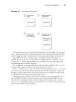
This is the end of the Setup Wizard. You are presented with the screen in Figure 15-17, from
which you can install Norton Internet Security on your computer if desired. If you choose
not to install this, click Finish to exit the wizard; you will see the Congratulations screen
shown in Figure 15-18.
Wireless Access Point Configuration: Linksys 300N Access Point 171
Figure 15-21 Confirm New Settings
Figure 15-22 Option to Install Norton Internet Security
172 Wireless Access Point Configuration: Linksys 300N Access Point
Figure 15-23 End of Wizard
After you have completed the Setup Wizard, you can use your Internet browser to connect
to the AP for management of the device. The default IP address is 192.168.1.1. Enter this
address in the address bar of your browser, and you will be prompted for a username and
password—the ones you set previously. Figure 15-19 shows the username/password
challenge window, and Figure 15-20 shows the main screen of the Linksys web-based
management utility.
Figure 15-21 shows the menu bar present in the web-based management utility. Selecting
any one of the main items—Setup, Wireless, Security, Access Restrictions, Applications &
Gaming, Administration, Status—will take you to a new screen with submenus for
additional management tasks. In Figure 15-21, the main button, Setup, has been selected,
and there are four screens that can be chosen: Basic Setup, DDNS, MAC Address Clone, or
Advanced Routing.
Wireless Access Point Configuration: Linksys 300N Access Point 173
Figure 15-24 Username/Password Challenge
Figure 15-25 Main Screen of Web-Based Management Utility
174 Wireless Client Configuration: Linksys Wireless-N Notebook Adapter
Figure 15-26 Web-Based Management Utility Menu Bar
Wireless Client Configuration: Linksys Wireless-N Notebook Adapter
NOTE: The wireless client card used in this chapter is the Linksys Wireless-N
Notebook Adapter. If you are using a different network adapter, the screen cap-
tures shown here might differ.
The operating system used in this chapter is Windows XP Professional, with Ser-
vice Pack 2 installed. If you are running Windows 2000, refer to the Linksys Quick
Start Handout that came with your adapter card for instructions on installing the
adapter card.
It is important to use the most up-to-date firmware or drivers. This is especially
true for the 300N client card because the 802.11n technology is still in draft stage.
Therefore, check your client card’s website for available updates. In the case of
Linksys, its website for updates is />Figure 15-22 shows the initial screen of the Setup Wizard, which runs automatically when
you use the installation CD provided with the client card. Run the Setup Wizard on the
computer before you plug in your client card to the PC.
Figure 15-27 GUI Setup Wizard
Wireless Client Configuration: Linksys Wireless-N Notebook Adapter 175
Figure 15-23 shows the license agreement for the device. After you have read the
agreement, click on Next to continue, or Cancel to exit the setup program.
Figure 15-28 License Agreement
The Setup Wizard then installs some files onto your computer. A window might appear
saying that this software has not passed Windows Logo Testing, as shown in Figure 15-24.
Click Continue Anyway to continue with the setup.
Figure 15-29 Software Installation
Figure 15-25 shows the next screen of the Setup Wizard, in which you are asked to insert
the adapter into either the PCMCIA or CardBus slot of your PC. Insert the card, and then
click Next.
176 Wireless Client Configuration: Linksys Wireless-N Notebook Adapter
Figure 15-30 Connecting the Adapter
A Found New Hardware Wizard pop-up window will appear, as shown in Figure 15-26.
Select Yes, this time only to the question “Can Windows connect to Windows Update to
search for software?” Then click Next to continue.
Figure 15-31 Found New Hardware Wizard
Figure 15-27 is the second screen of the Found New Hardware Wizard. Because you want
to install the software automatically for this adapter, you only have to click the Next button,
because that option is already highlighted in the wizard.
Wireless Client Configuration: Linksys Wireless-N Notebook Adapter 177
Figure 15-32 Found New Hardware Wizard Second Screen
A window may appear saying that this software has not passed Windows Logo Testing, as
shown previously in Figure 15-24. Click Continue Anyway to continue with the setup.
After the files have been successfully copied onto your hard drive, and the drivers have
been installed, the last screen of the Found New Hardware Wizard appears, as shown in
Figure 15-28. Click Finish to exit the wizard.
Figure 15-33 Completing the Found New Hardware Wizard
The next screen is the Creating a Profile screen, shown in Figure 15-29. Here you should
see all the available networks to which you can connect. If you do not see your network
listed, click the Refresh button. The network named lander78 in this screen shot is a
neighbor’s network. Notice that his security is disabled.
178 Wireless Client Configuration: Linksys Wireless-N Notebook Adapter
Figure 15-34 Creating a Profile: Available Wireless Networks
Because you set up security on the AP earlier in this chapter, you see the pop-up warning
shown in Figure 15-30. To connect to this network, you must enter your security settings
—
the same settings you configured on the AP earlier in this chapter. Figure 15-31 shows
the screen in which you enter the pre-shared key: grblnk99!!. Continue by clicking the
Connect button.
Figure 15-35 Security Warning
Wireless Client Configuration: Linksys Wireless-N Notebook Adapter 179
Figure 15-36 Security Connection
After connecting to your network, you will see the final screen of the wizard, the
Congratulations screen, shown in Figure 15-32. Click Finish to end the wizard.
Figure 15-37 Congratulations: End of Wizard
Figure 15-33 shows that the connection to the network is strong
—you have solid signal
strength and solid link quality. Signal strength is a measurement of the overall connection
between the client and the AP. Link quality is a measurement of bandwidth after removing
any noise/interference.
180 Wireless Client Configuration: Linksys Wireless-N Notebook Adapter
Figure 15-38 Link Information
From the screen shown in Figure 15-33, you can also choose to go to two other screens:
• Connect—Displays a list of available networks to join (see Figure 15-34)
• Profile—Displays the profiles created for this adapter (see Figure 15-35)
Figure 15-39 Connect Screen
Wireless Client Configuration: Linksys Wireless-N Notebook Adapter 181
Figure 15-40 Profiles Screen
Figure 15-36 shows the status of your wireless connection. In this case, it is Connection 2
because a built-in wireless adapter on this laptop is Connection 1. Note that with the draft
802.11n technology, the connection achieves a speed of 216 Mbps in the local LAN.
Figure 15-41 Wireless Network Connection Status
This page intentionally left blank
PART VII
Network
Administration and
Troubleshooting
Chapter 16 Backing Up and Restoring Cisco IOS Software
and Configurations
Chapter 17 Password Recovery Procedures and the
Configuration Register
Chapter 18 Cisco Discovery Protocol (CDP)
Chapter 19 Telnet and SSH
Chapter 20 The ping and traceroute Commands
Chapter 21 SNMP and Syslog
Chapter 22 Basic Troubleshooting
This page intentionally left blank
CHAPTER 16
Backing Up and Restoring
Cisco IOS Software and
Configurations
This chapter provides information and commands concerning the following topics:
• Boot system commands
• The Cisco IOS File System
• Backing up configurations to a TFTP server
• Restoring configurations from a TFTP server
• Backing up the Cisco IOS Software to a TFTP server
• Restoring/upgrading the Cisco IOS Software from a TFTP server
• Restoring the Cisco IOS Software from ROM Monitor mode using Xmodem
• Restoring the Cisco IOS Software using the ROM Monitor environmental
variables and tftpdnld command
Boot System Commands
If you enter boot system flash first, that is the first place the router will go to look for
the Cisco IOS Software. If you want to go to a TFTP server first, make sure that the
boot system tftp command is the first one you enter.
Router(config)#bb
bb
oo
oo
oo
oo
tt
tt
ss
ss
yy
yy
ss
ss
tt
tt
ee
ee
mm
mm
ff
ff
ll
ll
aa
aa
ss
ss
hh
hh
image-
name
Loads the Cisco IOS
Software with image-name.
Router(config)#bb
bb
oo
oo
oo
oo
tt
tt
ss
ss
yy
yy
ss
ss
tt
tt
ee
ee
mm
mm
tt
tt
ff
ff
tt
tt
pp
pp
image-name
11
11
77
77
22
22
11
11
66
66
11
11
00
00
33
33
Loads the Cisco IOS
Software with image-name
from a TFTP server.
Router(config)#bb
bb
oo
oo
oo
oo
tt
tt
ss
ss
yy
yy
ss
ss
tt
tt
ee
ee
mm
mm
rr
rr
oo
oo
mm
mm
Loads the Cisco IOS
Software from ROM.
Router(config)#ee
ee
xx
xx
ii
ii
tt
tt
Router#cc
cc
oo
oo
pp
pp
yy
yy
rr
rr
uu
uu
nn
nn
nn
nn
ii
ii
nn
nn
gg
gg
cc
cc
oo
oo
nn
nn
ff
ff
ii
ii
gg
gg
ss
ss
tt
tt
aa
aa
rr
rr
tt
tt
uu
uu
pp
pp
cc
cc
oo
oo
nn
nn
ff
ff
ii
ii
gg
gg
Saves the running
configuration to NVRAM.
The router will execute
commands in their order
on the next reload.
186 Backing Up Configurations to a TFTP Server
The Cisco IOS File System
NOTE: The Cisco IOS File System (IFS) provides a single interface to all the file
systems available on a routing device, including the flash memory file system;
network file systems such as TFTP, Remote Copy Protocol (RCP), and File Transfer
Protocol (FTP); and any other endpoint for reading and writing data, such as
NVRAM, or the running configuration.
The Cisco IFS minimizes the required prompting for many commands. Instead
of entering in an EXEC-level copy command and then having the system prompt
you for more information, you can enter a single command on one line with
all necessary information.
Backing Up Configurations to a TFTP Server
Cisco IOS Software Commands IFS Commands
cc
cc
oo
oo
pp
pp
yy
yy
tt
tt
ff
ff
tt
tt
pp
pp
rr
rr
uu
uu
nn
nn
nn
nn
ii
ii
nn
nn
gg
gg
cc
cc
oo
oo
nn
nn
ff
ff
ii
ii
gg
gg
cc
cc
oo
oo
pp
pp
yy
yy
tt
tt
ff
ff
tt
tt
pp
pp
::
::
ss
ss
yy
yy
ss
ss
tt
tt
ee
ee
mm
mm
::
::
rr
rr
uu
uu
nn
nn
nn
nn
ii
ii
nn
nn
gg
gg
cc
cc
oo
oo
nn
nn
ff
ff
ii
ii
gg
gg
cc
cc
oo
oo
pp
pp
yy
yy
tt
tt
ff
ff
tt
tt
pp
pp
ss
ss
tt
tt
aa
aa
rr
rr
tt
tt
uu
uu
pp
pp
cc
cc
oo
oo
nn
nn
ff
ff
ii
ii
gg
gg
cc
cc
oo
oo
pp
pp
yy
yy
tt
tt
ff
ff
tt
tt
pp
pp
::
::
nn
nn
vv
vv
rr
rr
aa
aa
mm
mm
::
::
ss
ss
tt
tt
aa
aa
rr
rr
tt
tt
uu
uu
pp
pp
cc
cc
oo
oo
nn
nn
ff
ff
ii
ii
gg
gg
ss
ss
hh
hh
oo
oo
ww
ww
ss
ss
tt
tt
aa
aa
rr
rr
tt
tt
uu
uu
pp
pp
cc
cc
oo
oo
nn
nn
ff
ff
ii
ii
gg
gg
mm
mm
oo
oo
rr
rr
ee
ee
nn
nn
vv
vv
rr
rr
aa
aa
mm
mm
::
::
ss
ss
tt
tt
aa
aa
rr
rr
tt
tt
uu
uu
pp
pp
cc
cc
oo
oo
nn
nn
ff
ff
ii
ii
gg
gg
ee
ee
rr
rr
aa
aa
ss
ss
ee
ee
ss
ss
tt
tt
aa
aa
rr
rr
tt
tt
uu
uu
pp
pp
cc
cc
oo
oo
nn
nn
ff
ff
ii
ii
gg
gg
ee
ee
rr
rr
aa
aa
ss
ss
ee
ee
nn
nn
vv
vv
rr
rr
aa
aa
mm
mm
::
::
cc
cc
oo
oo
pp
pp
yy
yy
rr
rr
uu
uu
nn
nn
nn
nn
ii
ii
nn
nn
gg
gg
cc
cc
oo
oo
nn
nn
ff
ff
ii
ii
gg
gg
ss
ss
tt
tt
aa
aa
rr
rr
tt
tt
uu
uu
pp
pp
cc
cc
oo
oo
nn
nn
ff
ff
ii
ii
gg
gg
cc
cc
oo
oo
pp
pp
yy
yy
ss
ss
yy
yy
ss
ss
tt
tt
ee
ee
mm
mm
::
::
rr
rr
uu
uu
nn
nn
nn
nn
ii
ii
nn
nn
gg
gg
cc
cc
oo
oo
nn
nn
ff
ff
ii
ii
gg
gg
nn
nn
vv
vv
rr
rr
aa
aa
mm
mm
::
::
ss
ss
tt
tt
aa
aa
rr
rr
tt
tt
uu
uu
pp
pp
cc
cc
oo
oo
nn
nn
ff
ff
ii
ii
gg
gg
cc
cc
oo
oo
pp
pp
yy
yy
rr
rr
uu
uu
nn
nn
nn
nn
ii
ii
nn
nn
gg
gg
cc
cc
oo
oo
nn
nn
ff
ff
ii
ii
gg
gg
tt
tt
ff
ff
tt
tt
pp
pp
cc
cc
oo
oo
pp
pp
yy
yy
ss
ss
yy
yy
ss
ss
tt
tt
ee
ee
mm
mm
::
::
rr
rr
uu
uu
nn
nn
nn
nn
ii
ii
nn
nn
gg
gg
cc
cc
oo
oo
nn
nn
ff
ff
ii
ii
gg
gg
tt
tt
ff
ff
tt
tt
pp
pp
::
::
ss
ss
hh
hh
oo
oo
ww
ww
rr
rr
uu
uu
nn
nn
nn
nn
ii
ii
nn
nn
gg
gg
cc
cc
oo
oo
nn
nn
ff
ff
ii
ii
gg
gg
mm
mm
oo
oo
rr
rr
ee
ee
ss
ss
yy
yy
ss
ss
tt
tt
ee
ee
mm
mm
::
::
rr
rr
uu
uu
nn
nn
nn
nn
ii
ii
nn
nn
gg
gg
cc
cc
oo
oo
nn
nn
ff
ff
ii
ii
gg
gg
Denver#cc
cc
oo
oo
pp
pp
yy
yy
rr
rr
uu
uu
nn
nn
nn
nn
ii
ii
nn
nn
gg
gg
cc
cc
oo
oo
nn
nn
ff
ff
ii
ii
gg
gg
ss
ss
tt
tt
aa
aa
rr
rr
tt
tt
uu
uu
pp
pp
cc
cc
oo
oo
nn
nn
ff
ff
ii
ii
gg
gg
Saves the running
configuration from DRAM
to NVRAM (locally).
Denver#cc
cc
oo
oo
pp
pp
yy
yy
rr
rr
uu
uu
nn
nn
nn
nn
ii
ii
nn
nn
gg
gg
cc
cc
oo
oo
nn
nn
ff
ff
ii
ii
gg
gg
tt
tt
ff
ff
tt
tt
pp
pp
Copies the running
configuration to the remote
TFTP server.
Address or name of remote host[ ]?
192.168.119.20
The IP address of the TFTP
server.
Restoring Configurations from a TFTP Server 187
NOTE: You can also use the preceding sequence for a copy startup-config tftp
command sequence.
Restoring Configurations from a TFTP Server
NOTE: You can also use the preceding sequence for a copy tftp startup-config
command sequence.
Destination Filename [Denver-confg]?®
The name to use for the file
saved on the TFTP server.
!!!!!!!!!!!!!!!
Each bang symbol (!) = 1
datagram of data.
624 bytes copied in 7.05 secs
Denver#
File has been transferred
successfully.
Denver#cc
cc
oo
oo
pp
pp
yy
yy
tt
tt
ff
ff
tt
tt
pp
pp
rr
rr
uu
uu
nn
nn
nn
nn
ii
ii
nn
nn
gg
gg
cc
cc
oo
oo
nn
nn
ff
ff
ii
ii
gg
gg
Copies the configuration
file from the TFTP server
to DRAM.
Address or name of remote host[ ]?
192.168.119.20
The IP address of the
TFTP server.
Source filename [ ]?Denver-confg
Enter the name of the file
you want to retrieve.
Destination filename [running-config]? ®
Accessing tftp://192.168.119.20/Denver-
confg…
Loading Denver-confg from 192.168.119.02
(via Fast Ethernet 0/0):
!!!!!!!!!!!!!!
[OK-624 bytes]
624 bytes copied in 9.45 secs
Denver#
File has been transferred
successfully.
188 Restoring/Upgrading the Cisco IOS Software from a TFTP Server
Backing Up the Cisco IOS Software to a TFTP Server
Restoring/Upgrading the Cisco IOS Software from a TFTP Server
Denver#cc
cc
oo
oo
pp
pp
yy
yy
ff
ff
ll
ll
aa
aa
ss
ss
hh
hh
tt
tt
ff
ff
tt
tt
pp
pp
Source filename [ ]? cc
cc
22
22
66
66
00
00
00
00
jj
jj
ss
ss
ll
ll
__
__
11
11
22
22
11
11
33
33
bb
bb
ii
ii
nn
nn
Name of the Cisco IOS
Software image.
Address or name of remote host [ ]?
11
11
99
99
22
22
11
11
66
66
88
88
11
11
11
11
99
99
22
22
00
00
The address of the TFTP
server.
Destination filename [c2600-js-l_121-3.bin]?
®
The destination filename
is the same as the source
filename, so just press
®.
!!!!!!!!!!!!!!!!!!!!!!!!!!!!!!!!!!!!!!!!!!!!!!
!!!!!!!!!!!!!!!!!!!!!!!!!!!!!!!!!!!!!!
8906589 bytes copied in 263.68 seconds
Denver#
Denver#cc
cc
oo
oo
pp
pp
yy
yy
tt
tt
ff
ff
tt
tt
pp
pp
ff
ff
ll
ll
aa
aa
ss
ss
hh
hh
Address or name of remote host [ ]?
11
11
99
99
22
22
11
11
66
66
88
88
11
11
11
11
99
99
22
22
00
00
Source filename [ ]? cc
cc
22
22
66
66
00
00
00
00
jj
jj
ss
ss
ll
ll
__
__
11
11
22
22
11
11
33
33
bb
bb
ii
ii
nn
nn
Destination filename [c2600-js-l_121-
3.bin]? ®
Accessing tftp://192.168.119.20/c2600-js-
l_121-3.bin
Erase flash: before copying? [confirm]
®
If flash memory is full, erase
it first.
Erasing the flash file system will remove
all files
Continue? [confirm] ®
Press Ç-C if you want to
cancel.
Restoring the Cisco IOS Software from ROM Monitor Mode Using Xmodem 189
Restoring the Cisco IOS Software from ROM Monitor Mode Using
Xmodem
The output that follows was taken from a 1720 router. Some of this output might vary from
yours, depending on the router model that you are using.
Erasing device eeeeeeeeeeeeeeeeee…erased
Each e represents data being
erased.
Loading c2600-js-l_121-3.bin from
192.168.119.20
(via) FastEthernet 0/0):
!!!!!!!!!!!!!!!!!!!!!!!!!!!!!!!!!!!!!!!!!!!!
!!!!!!!!!!!!!!!!!!!!!!!!!!!!!!!!!!!!!!!!!!!!
!!!
Each bang symbol (!) = 1
datagram of data.
Verifying Check sum ……………… OK
[OK – 8906589 Bytes]
8906589 bytes copied in 277.45 secs
Denver#
Success.
rommon 1 >cc
cc
oo
oo
nn
nn
ff
ff
rr
rr
ee
ee
gg
gg
Shows the configuration summary.
Step through the questions,
answering defaults until you can
change the console baud rate.
Change it to 115200; it makes
transfer go faster.
Configuration Summary
enabled are:
load rom after netboot fails
console baud: 9600
boot: image specified by the boot system
commands
or default to: cisco2-c1700
190 Restoring the Cisco IOS Software from ROM Monitor Mode Using Xmodem
do you wish to change the configuration?
y/n [n]: yy
yy
enable “diagnostic mode”? y/n [n]: nn
nn
enable “use net in IP bcast address”?
y/n [n]: nn
nn
disable “load rom after netboot
fails”? y/n [n]: nn
nn
enable “use all zero broadcast”? y/n
[n]: nn
nn
enable “break/abort has effect”? y/n
[n]: nn
nn
enable “ignore system config info”?
y/n [n]: nn
nn
change console baud rate? y/n [n]: yy
yy
enter rate: 0=9600, 1=4800, 2=1200,
3=2400
4=19200, 5=38400, 6=57600,
7=115200 [0]: 77
77
change the boot characteristics? y/n
[n]: nn
nn
Prompts begin to ask a series of
questions that allow you to change
the configuration register. Answer n
to all questions except the one that
asks you to change the console
baud rate. For the enter rate, choose
7 because that is the number that
represents a baud rate of 115200.
Configuration Summary
enabled are:
load rom after netboot fails
console baud: 115200
boot: image specified by the boot system
commands
or default to: cisco2-c1700
do you wish to change the configuration?
y/n [n]: nn
nn
rommon2>
After the summary is shown again,
choose n to not change the
configuration and go to the
rommon> prompt again.
rommon 2>rr
rr
ee
ee
ss
ss
ee
ee
tt
tt
Reloads the router at the new com
speed. Change the HyperTerminal
setting to 115200 to match the
router’s new console setting.
Rommon 1>xx
xx
mm
mm
oo
oo
dd
dd
ee
ee
mm
mm
cc
cc
11
11
77
77
00
00
00
00
jj
jj
ss
ss
ll
ll
__
__
11
11
22
22
11
11
33
33
bb
bb
ii
ii
nn
nn
Asking to transfer this image using
Xmodem.
…<output cut>…