designing network security cisco press phần 9 pptx
Bạn đang xem bản rút gọn của tài liệu. Xem và tải ngay bản đầy đủ của tài liệu tại đây (50.88 KB, 40 trang )
serial-number 007462E4
key-string
17C11157 CC640BF3 3DC5B608 C5C60963 C0421A67 D2D7AF70 97728A9A BACA0E07
35288070 AD90A20F 56F1BFE7 D8A4BB68 2C2419E0 26CF8E17 B09CA9A0 3090942E
quit
!
! Crypto map for the connection from Eesti to Vancouver-gw, this defines the remote
! peer, and what traffic to encrypt, which is determined by access list 140
! This gets applied to the tunnel and physical interfaces.
!
crypto map Eesti-to-Vancouver 10
set peer VancouverESA
match address 140
!
! Tunnel interface from remote branch (Eesti) to home gateway (Vancouver-gw)
!
interface Tunnel100
description network connection back to headquarters (Vancouver)
ip unnumbered Ethernet1/0
no ip directed-broadcast
tunnel source 207.9.31.1
tunnel destination 207.1.1.1
crypto map Eesti-to-Vancouver
Securing Dial-In Access
(62 of 103) [02/02/2001 17.33.17]
!
! Apply the crypto map to the physical interface,
! this is also the outside NAT interface.
!
interface Serial0/0
description frame relay connection to ISP
ip address 207.9.31.1 255.255.255.240
no ip directed-broadcast
ip nat outside
encapsulation frame-relay
frame-relay lmi-type ansi
crypto map Eesti-to-Vancouver
!
! NAT inside interface
!
interface Ethernet1/0
description private IP address for remote site
ip address 172.26.129.1 255.255.255.0
no ip directed-broadcast
ip nat inside
!
! Translate IP addresses matching access list 150 into the IP address
! given to serial interface connected to the ISP
Securing Dial-In Access
(63 of 103) [02/02/2001 17.33.17]
ip nat inside source list 150 interface Serial0/0 overload
ip classless
! default route to ISP
ip route 0.0.0.0 0.0.0.0 207.9.31.14
!
! Routes for the networks inside the corporate intranet that
! the remote needs to access
!
ip route 172.26.0.0 255.255.128.0 Tunnel100
ip route 172.20.0.0 255.255.0.0 Tunnel100
!
! Traffic going to any other destination will take the default route and be
! translated by NAT, access list 150 tells NAT what to translate.
!
access-list 150 permit ip 172.26.129.0 0.0.0.255 any
!
! ACL to determine what to be encrypted,
! all packets between the two tunnel endpoints.
!
access-list 140 permit gre host 207.9.31.1 host 207.1.1.1
!
line con 0
exec-timeout 2 30
Securing Dial-In Access
(64 of 103) [02/02/2001 17.33.17]
login authentication admin
!
line vty 0 4
exec-timeout 2 30
login authentication admin
L2TP with IPsec
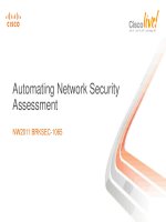
The example in Figure 10-9 shows the remote connection of a remote branch office in Toronto and a
remote branch office in New York connecting back to the corporate network in Denver. Both
connections are done through local ISPs and use the Internet as the way to transport the data back to the
corporate network in Denver. Mobile users also have access to the corporate network using local ISP
dial-up connections.
Figure 10-9: Virtual Dial-In Using L2TP with IPsec
The following security policy is defined for this example:
The branch office in Toronto is allowed to communicate directly to the Internet but must encrypt
all traffic going to the corporate network in Denver.
●
All New York branch office traffic must go through the Denver corporate office firewall.●
All mobile users use authenticated and private data connections back to the corporate network
through ISP collaborate agreements.
●
All corporate infrastructure device access is required to be authenticated and authorized for limited
access.
●
The policy is implemented as follows:
The branch office router in Toronto allows the users to talk directly to the Internet while using an
IPsec-encrypted tunnel to access the corporate network. The serial interface on the router has been
assigned an IP address from the ISP's address space. The Ethernet interface uses a private network
address, and NAT is used to translate traffic going to the Internet. This router uses static routing.
●
The branch router in New York requires that all traffic, even traffic to the Internet, must go
through the corporate firewall. The serial interface on the router has been assigned an IP address
●
Securing Dial-In Access
(65 of 103) [02/02/2001 17.33.17]
from the ISP's address space; the Ethernet interface uses a private network address. This router
uses OSPF routing.
There is an agreement between the ISP and the corporation that if a mobile user presents the ISP's
NAS with a username in the format , the PPP session will be transported to
the corporation's home gateway for termination. Using L2TP tunneling with IPsec, a secure tunnel
is provided from the NAS (isp-nas) to the home gateway (Denver-gw).
●
Home Gateway Router Configuration:
hostname Denver-gw
!
! In IOS firewall IPsec images "no service tcp & no udp small servers" is the
! default so it does not have to be explicitly defined.
! Turn on timestamps for log and debug information, set to the local time with
! timezone information displayed.
!
service timestamps debug datetime msec localtime show-timezone
service timestamps log datetime msec localtime show-timezone
!
service password-encryption
!
no logging console
!
! Enable TACACS+ to authenticate login, enable any PPP sessions, also enable
! accounting start-stop records for EXEC and PPP sessions
!
aaa new-model
aaa authentication login default tacacs+ enable
Securing Dial-In Access
(66 of 103) [02/02/2001 17.33.17]
aaa authentication login console none
aaa authentication enable default tacacs+ enable
aaa authentication ppp default tacacs+
aaa authorization network default tacacs+
aaa accounting exec default start-stop tacacs+
aaa accounting network default start-stop tacacs+
!
enable secret 5 $1$xDvT$sT/TGeGrAwfAKbMr4N1NZ1
enable password 7 02050D480809
!
no ip finger
ip domain-name mkos.com
!
! Enable VPDN and tell it to use L2TP. The PPP name of the remote NAS will be
! isp-nas and the local PPP name is Denver-gw. Also for the VPDN, use an
! alternative tacacs+ server. Connections inbound will use virtual-template 1
! as the basis to create to the actual virtual-access interface.
!
vpdn enable
!
vpdn aaa override-server 172.20.24.47
vpdn-group 1
accept dialin l2tp virtual-template 1 remote isp-nas
Securing Dial-In Access
(67 of 103) [02/02/2001 17.33.17]
local name Denver-gw
!
! Define the IPsec transform policy set, (ah-sha-hmac) AH with SHA
! authentication algorithm, (esp-des) ESP with 56-bit DES encryption algorithm,
! (esp-sha-hmac) ESP with SHA authentication algorithm. Because a GRE is used,
! run IPsec in transport rather than tunnel mode.
!
crypto ipsec transform-set auth2 ah-sha-hmac esp-des esp-sha-hmac
mode transport
!
! IPsec using certificates: The routers must first obtain certificates from
! the Certificate Authority (CA) server. When both peers have valid certificates,
! they automatically exchange RSA public keys as part of the ISAKMP negotiation.
! All that is required is that the routers register with the CA and obtain
! a certificate. A router does not have to keep public RSA keys for all peers
! in the network.
!
crypto ca identity vpnnetwork
enrollment url http://mkosca
crl optional
cryto ca certificate chain vpnnetwork
certificate 44FC6C531FC3446927E4EE307A806B20
Securing Dial-In Access
(68 of 103) [02/02/2001 17.33.17]
! Certificate is multiple lines of hex digits
quit
certificate ca 3051DF7169BEE31B821DFE4B3A338E5F
! Certificate of the CA, multiple of lines hex digits
quit
certificate 52A46D5D10B18A6F51E6BC735A36508C
! Certificate is multiple lines of hex digits
quit
!
! The crypto map determines what to encrypt and to what peer to send the traffic.
! An interface can have only one crypto map applied to it. The crypto map below
! is structured into sections, which apply for the different destinations,
! while still being a single crypto map entity.
!
crypto map Denver-to-remotes local-address Serial2/0
crypto map Denver-to-remotes 100 ipsec-isakmp
set peer 207.9.31.1
set transform-set auth2
match address Denver_gre_Toronto
crypto map Denver-to-remotes 200 ipsec-isakmp
set peer 207.10.31.1
set transform-set auth2
match address Denver_gre_NewYork
Securing Dial-In Access
(69 of 103) [02/02/2001 17.33.17]
crypto map Denver-to-remotes 500 ipsec-isakmp
set peer 201.1.1.1
set transform-set auth2
match address ISP1_VPDN
!
! Set the timezone and daylight savings time for this router.
!
clock timezone PST -8
clock summer-time PDT recurring
!
! Tunnel interface to router Toronto. The tunnel source is specified as an
! interface with a registered IP address. The crypto map is applied to both
! the tunnel and physical interfaces. The IP precedence of packets being
! tunneled are copied into the IP header of the outbound frame.
! This example uses an IP unnumbered tunnel interface. Only packets destined
! for the intranet arrive on this interface because NAT is used at the remote
! for packets destined for the Internet.
!
interface Tunnel100
description tunnel to branch router Toronto
ip unnumbered FastEthernet5/0
no ip directed-broadcast
tunnel source Serial2/0
Securing Dial-In Access
(70 of 103) [02/02/2001 17.33.17]
tunnel destination 207.9.31.1
crypto map Denver-to-remotes
!
! Tunnel interface to router New York. The crypto map is applied to both the
! tunnel and physical interfaces. Note that the same crypto map has been used
! on both the tunnels, with different sections of the crypto map applying to each
! tunnel. The IP precedence of packets being tunneled are copied into the IP
! header of the outbound frame. This example uses an IP-numbered tunnel interface
! with OSPF as the routing protocol and routing information authentication
! enabled. The policy for this remote site is that all packets destined to the
! Internet must go through the corporate firewall. This is achieved by using
! policy routing (route-map VPN_InBound).
!
interface Tunnel101
description tunnel to branch router NewYork
ip address 172.26.123.1 255.255.255.252
no ip directed-broadcast
ip ospf message-digest-key 1 md5 7 00071A15075434101F2F
ip policy route-map VPN_InBound
tunnel source Serial2/0
tunnel destination 207.10.31.1
crypto map Denver-to-remotes
!
Securing Dial-In Access
(71 of 103) [02/02/2001 17.33.17]
! DS3 connection to ISP. Two ACLS are applied here. The inbound ACL stops
! some common protocols and network addresses known to be invalid or harmful.
! The outbound security ACL prevents packets from private network addresses
! that have not been through NAT from leaving. The crypto map is applied
! to the interface.
!
interface Serial2/0
description connection to ISP1 - DS3
ip address 207.1.1.1 255.255.255.252
ip access-group IntSecurity in
ip access-group IntSecurityOut out
no ip directed-broadcast
framing c-bit
cablelength 50
dsu bandwidth 44210
crypto map Denver-to-remotes
!
! This interface is connected to the corporate network Web server and to the
! firewall, which is doing NAT for the corporate network's access to the
! Internet.
!
interface FastEthernet3/0
description network for Internet traffic
Securing Dial-In Access
(72 of 103) [02/02/2001 17.33.17]
ip address 207.1.2.1 255.255.255.240
no ip directed-broadcast
full-duplex
!
! This interface is connected to the firewall, is treated as an inside interface,
! is for the VPN traffic to access the corporate network, and is using NAT
! on the firewall to the Internet. This route-map on the interface is responsible
! for setting the correct precedence on the IP packets destined for the VPN,
! to gain the QoS agreement with the service provider. The ACL is used to allow
! only known VPN networks on the link.
!
interface FastEthernet5/0
description network for VPN traffic
ip address 172.26.71.1 255.255.255.252
ip access-group 120 out
no ip directed-broadcast
ip policy route-map VPN_QoS
full-duplex
!
! The virtual template is used by the VPDN code as the basis to create the
! virtual-access interface on which the L2TP connections terminate.
!
interface Virtual-Template1
Securing Dial-In Access
(73 of 103) [02/02/2001 17.33.17]
ip unnumbered FastEthernet5/0
no ip directed-broadcast
peer default ip address pool vpn_users
!
! OSPF for the VPN network, remote branch NewYork is running OSPF.
! The OSPF process is set to redistribute static routes that match
! route-map VPN_ROUTES_OUT, and originate the default route for the
! remote VPN sites running OSPF. Authentication is enabled for routing
! information so that only remotes with the correct key can participate.
!
router ospf 100
redistribute static subnets route-map VPN_ROUTES_OUT
passive-interface FastEthernet5/0
passive-interface Tunnel100
network 172.26.71.0 0.0.0.3 area 0
network 172.26.120.0 0.0.3.255 area 172.26.120.0
default-information originate
area 172.26.120.0 authentication message-digest
!
ip classless
!
! Default route to ISP
ip route 0.0.0.0 0.0.0.0 207.1.1.2
Securing Dial-In Access
(74 of 103) [02/02/2001 17.33.17]
!
! Corporate network uses 172.20/24 and 172.26/24.
ip route 172.20.0.0 255.255.0.0 172.26.71.2
ip route 172.26.0.0 255.255.0.0 172.26.71.2
!
! Static route to branch in Toronto (Ethernet 0)
ip route 172.26.120.0 255.255.255.0 Tunnel100
!
! Route to the NAT pool on the firewall
ip route 207.1.2.16 255.255.255.248 207.1.2.2
!
! ACL to determine what frames get set specified QoS for ISP1
ip access-list extended Bronze_ISP1_QoS
permit ip 172.26.0.0 0.0.255.255 172.26.120.0 0.0.0.255
permit ip 172.20.0.0 0.0.255.255 172.26.120.0 0.0.0.255
!
! ACL to determine the traffic to encrypt for the VPDN L2TP tunnel
! from ISP NAS "isp-nas"
ip access-list extended ISP1_VPDN
permit ip host 207.1.1.1 host 201.1.1.1
!
! ACL to block any traffic inbound from private addresses
! and some common troublesome services
Securing Dial-In Access
(75 of 103) [02/02/2001 17.33.17]
ip access-list extended IntSecurity
permit tcp any any established
deny ip 127.0.0.0 0.255.255.255 any
deny ip 10.0.0.0 0.255.255.255 any
deny ip 172.16.0.0 0.15.255.255 any
deny ip 192.168.0.0 0.0.255.255 any
deny udp any any eq snmp
deny udp any any eq 2000
deny udp any any gt 6000
deny tcp any any gt 6000
deny tcp any any eq 2000
deny udp any any eq tftp
deny udp any any eq sunrpc
deny udp any any eq 2049
deny tcp any any eq 2049
deny tcp any any eq sunrpc
deny tcp any any eq 87
deny tcp any any eq exec
deny tcp any any eq login
deny tcp any any eq cmd
deny tcp any any eq lpd
deny tcp any any eq uucp
permit ip any any
Securing Dial-In Access
(76 of 103) [02/02/2001 17.33.17]
!
! ACL to prevent any packets from private addresses being sent to the Internet.
ip access-list extended IntSecurityOut
deny ip 127.0.0.0 0.255.255.255 any
deny ip 10.0.0.0 0.255.255.255 any
deny ip 172.16.0.0 0.15.255.255 any
deny ip 192.168.0.0 0.0.255.255 any
permit ip 207.0.0.0 0.255.255.255 any
!
! ACL to determine which frames are set to Silver QoS for ISP1
ip access-list extended Silver_ISP1_QoS
permit ip 172.26.0.0 0.0.255.255 172.26.121.0 0.0.0.255
permit ip 172.20.0.0 0.0.255.255 172.26.121.0 0.0.0.255
!
! ACL determines which packets IPsec will look at for tunnel100
ip access-list extended Denver_gre_Torornto
permit gre host 207.1.1.1 host 207.9.31.1
!
! ACL determines which packets IPsec looks at for tunnel101
ip access-list extended Denver_gre_NewYork
permit gre host 207.1.1.1 host 207.10.31.1
!
! Turn on syslog and point it at the management station.
Securing Dial-In Access
(77 of 103) [02/02/2001 17.33.17]
logging 172.20.18.5
!
! ACL determines which static routes are redistributed into the OSPF VPN process
access-list 18 permit 172.26.0.0 0.0.255.255
access-list 18 permit 172.20.0.0 0.0.255.255
!
! ACL only allows Telnet to the router from particular subnets
access-list 70 permit 172.20.18.0 0.0.0.192
access-list 70 permit 172.20.24.0 0.0.0.255
!
! ACL determines which management stations can access this device using SNMP
access-list 75 permit 172.20.18.0 0.0.0.255
!
! ACL only allows particular networks on the VPN interface to the firewall
access-list 120 permit ip 172.26.120.0 0.0.0.255 any
access-list 120 permit ip 172.26.121.0 0.0.0.255 any
access-list 120 permit ip 172.26.122.0 0.0.0.255 any
access-list 120 permit ip 172.26.123.0 0.0.0.255 any
!
! ACL for route map to policy route all packets to the firewall.
access-list 195 permit ip 172.26.121.0 0.0.0.255 any
access-list 195 permit ip 172.26.123.0 0.0.0.3 any
!
Securing Dial-In Access
(78 of 103) [02/02/2001 17.33.17]
! Route map determines which routes to distribute into OSPF VPN process
route-map VPN_ROUTES_OUT permit 20
match ip address 18
set metric 1000
set metric-type type-1
!
! Route map used to policy route all specified packets to the corporate firewall
route-map VPN_InBound permit 100
match ip address 195
set ip next-hop 172.26.71.2
!
! Route map used to set the precedence bits on outbound VPN network packets
route-map VPN_QoS permit 100
match ip address Bronze_ISP1_QoS
set ip precedence priority
route-map VPN_QoS permit 200
match ip address Silver_ISP1_QoS
set ip precedence immediate
!
! Configure SNMP, only allow management stations matching access list 75
! to manage this router
snmp-server community public RO 75
snmp-server community private RW 75
Securing Dial-In Access
(79 of 103) [02/02/2001 17.33.17]
snmp-server trap-source Ethernet1/0
snmp-server packetsize 4096
snmp-server enable traps snmp
snmp-server enable traps frame-relay
snmp-server host 172.20.18.5 traps public
snmp-server tftp-server-list 75
!
! Configure which TACACS server to use and the key.
tacacs-server host 172.20.18.5
tacacs-server key SECRET12345
!
! Console and vty are secured using TACACS+
line con 0
exec-timeout 5 0
transport input none
line aux 0
!
! Only allow Telnet to this router if the source address is in access list 70
line vty 0 4
access-class 70 in
password 7 1511021F0725
transport input telnet
!
Securing Dial-In Access
(80 of 103) [02/02/2001 17.33.17]
! Configure NTP so that all the routers have the same time in the network.
ntp clock-period 17179770
ntp server 172.26.71.2
end
Remote Branch Router in Toronto Configuration:
hostname Toronto
!
! In IOS firewall IPsec images "no service tcp & no udp small servers" is the
! default. Turn on timestamps for log and debug information and set to the local
! time with timezone information displayed.
!
service timestamps debug datetime msec localtime show-timezone
service timestamps log datetime msec localtime show-timezone
service password-encryption
!
logging buffered 32000 debugging
no logging console
!
! Enable TACACS+ to authenticate login and enable passwords,
! also enable accounting start-stop records for exec sessions
!
aaa new-model
aaa authentication login default tacacs+ enable
Securing Dial-In Access
(81 of 103) [02/02/2001 17.33.17]
aaa authentication enable default tacacs+ enable
aaa accounting exec default start-stop tacacs+
!
enable secret 5 $1$SKkd$qbTmOJ9dyffjccNUB0cvn0
enable password 7 02050D480809
!
no ip finger
ip domain-name mkos.com
!
! Define the IPsec transform policy set; because a GRE is used, run IPsec in
! transport rather than tunnel mode.
!
crypto ipsec transform-set auth2 ah-sha-hmac esp-des esp-sha-hmac
mode transport
!
crypto ca identity vpnnetwork
enrollment url http://mkosca
crl optional
cryto ca certificate chain vpnnetwork
certificate 44FC6C531FC3446927E4EE307A806B20
! Certificate is multiple lines hex digits
quit
certificate ca 3051DF7169BEE31B821DFE4B3A338E5F
Securing Dial-In Access
(82 of 103) [02/02/2001 17.33.17]
! Certificate is multiple lines hex digits
quit
certificate 52A46D5D10B18A6F51E6BC735A36508C
! Certificate is multiple lines hex digits
quit
!
! The crypto map determines what packets should be encrypted as determined by
! access list 140, and the crypto peer that is the IP address of Denver-gw,
! along with the transforms that will be allowed. The setting of the local-address
! ensures that if there are multiple paths, the same IP address is always used
! for this crypto pair, no matter what interface a packet arrives on.
!
crypto map ipsec-Toronto-to-Denver local-address Serial0/0
crypto map ipsec-Toronto-to-Denver 10 ipsec-isakmp
set peer 207.1.1.1
set transform-set auth2
match address 140
!
! Set the timezone and daylight savings time for this router
!
clock timezone EST -5
clock summer-time EDT recurring
!
Securing Dial-In Access
(83 of 103) [02/02/2001 17.33.17]
! Tunnel interface to transport traffic to Denver-gw, the tunnel source is
! specified as an interface with a registered IP address. The IP address of
! the Ethernet is used, which is a private address; an unnumbered interface
! is used here to show that you do not have to address the tunnel interface.
! The IP precedence of the packets being tunneled are copied into the IP header
! of the outbound frame.
!
interface Tunnel100
description VPN connection back to headquarters (Denver)
ip unnumbered Ethernet1/0
no ip directed-broadcast
tunnel source Serial0/0
tunnel destination 207.1.1.1
crypto map ipsec-Toronto-to-Denver
!
! Serial 0/0 is the connection to the ISP; it has one of the ISP's registered
! addresses. Two access lists are applied to the interface: one inbound and
! one outbound. These are explained where the access list is defined below.
! This interface is specified as the outside interface for NAT.
! Finally, the crypto map is applied to the interface to determine what
! should be encrypted.
!
interface Serial0/0
Securing Dial-In Access
(84 of 103) [02/02/2001 17.33.17]
description frame relay connection to ISP
ip address 207.9.31.1 255.255.255.240
ip access-group IntSecurity in
ip access-group IntSecurityOut out
no ip directed-broadcast
ip nat outside
encapsulation frame-relay IETF
no ip mroute-cache
frame-relay lmi-type ansi
crypto map ipsec-Toronto-to-Denver
!
! Ethernet 1/0 is the remote LAN interface; it is assigned a private IP address
! and is a NAT inside interface. A route-map is applied to the interface to set
! the IP precedence to get the ISP Bronze offering of QoS.
!
interface Ethernet1/0
description private IP address for remote site
ip address 172.26.120.1 255.255.255.0
no ip directed-broadcast
ip nat inside
ip policy route-map Bronze_ISP1_QoS
!
! Configure NAT: Any source address matching access list 150,
Securing Dial-In Access
(85 of 103) [02/02/2001 17.33.17]
! translate to the IP address of interface serial 0/0. The overload options
! mean that many IP addresses will be translated to serial 0/0 IP addresses
! on different ports.
!
ip nat inside source list 150 interface Serial0/0 overload
ip classless
!
! Static routes: The default is to send all traffic to the ISP. The corporation
! uses networks 172.20/24 and 172.26/24 for its networks, so any traffic
! destined to these addresses should go across the tunnel interface.
!
ip route 0.0.0.0 0.0.0.0 207.9.31.14
ip route 172.20.0.0 255.255.0.0 Tunnel100
ip route 172.26.0.0 255.255.0.0 Tunnel100
!
! ACL to block particular services and networks, inbound from the ISP.
ip access-list extended IntSecurity
permit tcp any any established
deny ip 127.0.0.0 0.255.255.255 any
deny ip 10.0.0.0 0.255.255.255 any
deny ip 172.16.0.0 0.15.255.255 any
deny ip 192.168.0.0 0.0.255.255 any
deny udp any any eq snmp
Securing Dial-In Access
(86 of 103) [02/02/2001 17.33.17]