Wireless Networks dor Dummies phần 7 potx
Bạn đang xem bản rút gọn của tài liệu. Xem và tải ngay bản đầy đủ của tài liệu tại đây (1.28 MB, 41 trang )
Considering Layer 2 Tunneling Protocol
Microsoft’s implementations of Layer 2 Tunneling Protocol (L2TP) and
Internet Protocol Security (IPSec) are available on the Windows 2000 and
2003 platforms and are designed to provide the highest possible security.
Unfortunately, as a result of this increased level of security, these VPN solu-
tions require the deployment of a Public Key Infrastructure, along with
Pentium-class processors.
A Microsoft L2TP/IPSec VPN Client is available that allows computers running
Windows 98, Windows Me, and even legacy Windows NT Workstation 4.0 to
use L2TP connections with IPSec. I doubt very much if anyone still uses these
clients; they are so old. However, should you be one of those, I have three
words for you: Get new clients. Easy, eh? Really, neither of the Windows
98/Me clients offers security, and NT is no longer supported. You should be
moving up to XP by now for the added support, security, and total cost of
operation benefits available.
L2TP allows IP, IPX, or NetBEUI traffic to be encrypted, as we mentioned ear-
lier, and then sent over any of the various network types, such as IP (the most
obvious for us), X.25, Frame Relay, or ATM.
L2TP uses IPSec to start encryption earlier than the PPTP connection, provid-
ing greater security. It also allows for stronger encryption algorithms to pro-
tect the data.
Finally, IPSec provides data integrity, which proves that the data isn’t modi-
fied in transit; replay protection, which prevents anyone from resending a
captured packet stream; and data confidentiality by using encryption. PPTP
only provides data confidentiality.
As we mention earlier, this is a more robust, secure method but needs more
work to implement it. Perhaps in another book.
Using Windows IPSec
IPSec is an industry standard for encryption that Microsoft includes in its
newer Windows 2000, XP, and 2003 operating systems. It is reasonably easy to
set up between Windows machines and offers excellent security. Its primary
weakness for the small business owner is its need for a certificate server or
third-party certificate to ensure encryption. As you already noticed, it is typi-
cally used in conjunction with the L2TP protocol.
225
Chapter 12: Secure Wireless Access with Virtual Private Networking
17_575252 ch12.qxd 9/2/04 4:06 PM Page 225
IPSec has two encryption modes: tunnel and transport. Tunnel encrypts the
header and the payload of each packet, while transport only encrypts the
payload. On your inside network, transport is sufficient because you are less
concerned about anyone knowing your network topology, since they are
likely authorized users who know the IP address ranges anyway.
One reason for using transport mode inside the network is the small gain in
encryption speed; however, for a small network, the overall cost in speed of
encrypting traffic is minimal. One Microsoft expert we talked to said it costs
about 1 to 1.5 percent of the network bandwidth to use an IPSec tunnel. That
is a pittance compared to the overall enhancement in security that is gained.
Remote access, however, definitely requires tunnel mode to hide those inside
IP addresses from prying eyes.
IPSec is a good method of protecting your wireless network if all your client
workstations and servers are Windows 2000, XP, or 2003. After setup, no one
is able to see any of the traffic between machines unless they have the proper
credentials. However, IPSec tunnels only support IP traffic and therefore cannot
be used for IPX or other network traffic.
While IPSec is not overly difficult to set up, it is beyond what we can provide
in this book. Use the Microsoft Web site and download one of their excellent
Step-by-Step series of articles, one of which guides you through using IPSec
between Windows machines.
Oldies but goodies — SSH2
SSH is an abbreviation that stands for Secure Shell, which is a program allow-
ing you to secure network services running over an insecure network, such
as the Internet. This is another tunnel, similar in idea to the ones we have dis-
cussed throughout this chapter.
The Secure Shell concept originated on Unix and therefore has been around
the block, so to speak. Its origin goes back to the early days of Unix and a
need to protect the weak services that Unix had implemented. Today, it is
commonly used to tunnel services with cleartext passwords such as Telnet
and FTP. These dinosaurs are widely used and effective, hence their popular-
ity, but they use cleartext passwords! It boggles the mind that in today’s com-
puting world, so many organizations think so little of security that they still
use such tools.
The current version of SSH is version 2 (hence the SSH2 in a title of this sec-
tion). Discover details about it in the IETF-secsh Internet-Drafts on the site
226
Part III: Using Your Network Securely
17_575252 ch12.qxd 9/2/04 4:06 PM Page 226
www.ietf.org/ID.html. There is more available information than you ever
wanted if you search through all the various drafts.
SSH also allows you to securely log in to remote host computers, just like we
do using PPTP. This allows you to run commands on a remote machine, pro-
viding secure encrypted and authenticated communications between two
machines or networks. Within this tunnel, you run the services you want to
protect, such as e-mail, FTP, or even Web browsing. Barry tunnels a number
of items, including his e-mail, Web browsing, and even a Terminal Services
connection to an inside server.
To use SSH, you need to operate the server portion of the program on a
machine inside your network. You then use the client to connect to this
server software and establish a tunnel. SSH server is free within the Unix
world and is often installed by default, making it kind of easy to use. But as
time and Windows advanced across the world, the need for a Windows ver-
sion of SSH became evident, and that need was fulfilled, allowing you to use
this oldie but goodie even in that competing product line. The downside, of
course, is that the SSH Server for Windows doesn’t come free, costing around
a thousand dollars.
The good news for the financially strapped is the possibility of using a free
Unix SSH server and letting your Windows clients connect to that. Client soft-
ware that recognizes either Unix or Windows servers is available for all the
major workstation operating systems.
SSH provides mutual authentication as the client authenticates the server,
and the server authenticates the client. This way, both parties can be sure
they are dealing with the correct party. Each party uses either certificates or
public keys to ensure the identity of the other.
As we mention earlier in this chapter, Barry uses two remote access meth-
ods. This is his second method for getting into his home office network. He
set this up a number of years ago with the able assistance of a good friend so
that they can use these tunnels to connect to the outside world while on
assignment with various clients.
Finally, one of the really good things about SSH is its ability to use public key
cryptography or certificates. This is far stronger than a mere password.
There is a great deal of good information at
www.ssh.com. We recommend
visiting the site to learn more about SSH, including the steps needed to imple-
ment and support it.
227
Chapter 12: Secure Wireless Access with Virtual Private Networking
17_575252 ch12.qxd 9/2/04 4:06 PM Page 227
Who Is Doing the Talking?
We all recognize that some communications require confidentiality, integrity,
and authentication — the foundations of security. The adoption of crypto-
graphic techniques or, more commonly, encryption and the keys used within
that, provides the degree of security needed. Putting such encryption into
place, along with the ongoing management of the keys and algorithms, needs
an infrastructure. This infrastructure is commonly referred to as a Public-Key
Infrastructure, or PKI.
On the plus side, using a PKI immensely enhances your security and allows
you unbridled freedom to perform business over any network. On the down-
side, putting this structure into place and then managing the day-to-day oper-
ation of it is expensive and requires considerable technical expertise.
This PKI methodology is being adapted and optimized to fit the wireless
world’s (WPKI) needs. It consists of the same components that are used in a
traditional PKI. These include an End-Entity (EE), the Registration Authority
(RA), the Certification Authority (CA), and the PKI directory. In addition, a
new component referred to as the PKI Portal is required.
Remember, you can think of a PKI as being the components that allow you to
use certificates and encryption along with all the parts you need to put them
together and manage them. However, few organizations today are using a PKI
mainly due to the complexity and cost, along with different competing stan-
dards that make sharing a PKI between business partners difficult.
Simply put, the steps involved in using such a mechanism after it is installed
include the user’s End-Entity software requesting a certificate from the PKI
Portal, which forwards the request to a Certification Server. The Certificate
Server issues the certificate and posts it in a directory for later use. The
portal sends the location of the certificate back to the End-Entity that
requested it. Content servers use the directory to retrieve the certificate and
its revocation dates for use in authenticating the user. The user device then
uses that certificate to issue secure requests to applications, such as Web
portals, and the data flows in an encrypted form between the user device and
the application, ensuring that no one sees or tampers with the information.
This is all great stuff isn’t it? However, this short explanation doesn’t really
touch on the complexities involved in implementing a Wireless PKI (or any
PKI for that matter). It might highlight for you, though, that such technology
is available and, should your business have such a need, you can implement
fully secure methods of accessing your applications across a hostile, open
network such as the Internet.
228
Part III: Using Your Network Securely
17_575252 ch12.qxd 9/2/04 4:06 PM Page 228
Part IV
Keeping Your
Network on the
Air — Administration
and Troubleshooting
18_575252 pt04.qxd 9/2/04 4:07 PM Page 229
In this part . . .
A
fter you plan, set up, connect, and secure your wire-
less network, you must manage that network and
keep it up and on the air. Troubleshooting a wireless net-
work involves far different issues than troubleshooting a
wired network, including Fresnel zones, free space loss,
and contention issues. Luckily, this part provides direc-
tion on those issues as well as providing you with sound
advice on expanding the distance of your network using
bridging techniques. You see how to perform traffic man-
agement and learn how to monitor for performance issues
and trouble spots. Finally, in this part, you see how to find
all your access points and detect and respond to intrusion.
18_575252 pt04.qxd 9/2/04 4:07 PM Page 230
Chapter 13
Problems with Keeping on the Air
In This Chapter
ᮣ More on troubleshooting your wireless network
ᮣ Learning about the Fresnel zone
ᮣ You don’t want to interfere, but sometimes your paths cross
ᮣ Close counts only in horseshoes
ᮣ Breaking up is still hard to do
T
his chapter helps set out processes and steps for managing that new wire-
less network and ensuring that it runs as trouble-free as possible. Like any
network, implementing it is the first step, but living with the results and con-
stantly tweaking the parameters to keep the network humming is another thing
altogether. Sometimes it can be tough to be the network person. We help ease
that burden by providing information on typical trouble spots and how you can
prepare to overcome them.
Troubleshooting Redux
In Chapter 16, we discuss a number of tools and methods for helping run a
wireless network; there, we also recommend annual audits to ensure that it
remains functional and secure. Here we discuss an approach to troubleshoot-
ing to provide you with enough information to discover where problems are —
and how they might be resolved.
We notice that true analytical troubleshooting capabilities seem hard to find.
Folks know their products and equipment but are hard-pressed to take a step-
by-step approach to analyzing the issue, research methods, or techniques
to resolve the issue and implement the solution. Too often, we see network
people misunderstand the actual issue and take inappropriate steps or place
blame where it doesn’t belong instead of attempting to solve the problem. We
show you one way to bypass all that and actually fix the problem.
19_575252 ch13.qxd 9/2/04 4:07 PM Page 231
The following broadly defined steps are a good starting point:
1. Know your network. What does it consist of in terms of access points,
users, LAN connections, and client devices?
2. Determine the actual problem. Much effort is wasted analyzing a problem
that doesn’t exist because someone used the effect instead of the cause
as the base assumption.
3. Get help early. Don’t waste time thinking that you can do it all. Know
where your technical library is and who is strongest on each aspect of
your network. A team is always better than one.
4. Break the problem down into components and review each one. Is the prob-
lem that users cannot connect? Then determine precisely where they
cannot connect, when they cannot connect, how they are attempting to
connect, and what exactly happens when they attempt to connect.
Often, getting the exact information from the user rather than their
translation of that evidence helps immensely.
5. Determine which aspect of the network is failing. Avoid using the effect
that a user is experiencing; that can be misleading. Step through each
component and ensure that it is functioning correctly until you reach the
actual problem area. Although it may seem intuitive to just go right to
the cause, you can often solve the problem faster by being rigorous in
your approach.
6. Fix one problem at a time. Doing too much at once can hide the real solu-
tion. Try one thing at a time, noting what happens and whether it repairs
the problem before trying the next thing.
7. Don’t automatically assume two things are broken at once. Although this
is possible, it’s unlikely and only complicates your efforts.
8. Isolate components where possible and see whether they work correctly
before placing them back on the network. However, don’t just swap parts.
This does nothing to increase your problem determination skills.
9. After the issue is identified and repaired, test it. Be sure it is working and
that you know why it didn’t.
10. Document the issue, its cause and effect, and how it was resolved. Building
a troubleshooting document can pay dividends the next time something
happens.
You can obtain oodles of information from the vendors of your products,
including common troubleshooting steps and specific details on configuration
errors. Use these resources.
Table 13-1 describes some common errors that occur.
232
Part IV: Keeping Your Network on the Air — Administration & Troubleshooting
19_575252 ch13.qxd 9/2/04 4:07 PM Page 232
Table 13-1 Common Configuration and Other Errors
Error What to Do
Unplugged You’d be amazed at how often a component is
unplugged accidentally. Check it first.
Loose cable Check all connections and ensure that they are tightly
coupled.
Disconnected Ping each component on the network and ensure that
you can reach them.
Network card Is the user’s network card functioning correctly? Often,
malfunctioning this is the problem and not the rest of the network. Verify
that it is properly installed.
Incorrect SSID Ensure that the user has the correct SSID or network
name in her wireless network card.
Incorrect channel Make sure that all devices are communicating on the
correct channel. This is 1–11 for North America.
Incompatible standards Are all the devices using compatible 802.11 standards?
Remember that a client with an 802.11b network card
will be unable to use an 802.11a access point.
Inaccurate WEP/WPA Has the user inadvertently turned off WEP or keyed in
settings the incorrect key? Is WPA configured accurately?
Network address Is DHCP working correctly and assigning the correct IP
incorrect addresses? Do an
ipconfig /all command on
Windows clients and ensure that the IP address
information is correct.
Dual DHCP Are multiple access points each using DHCP? If so,
check for conflicts and set each one to supply only
particular subnets.
MAC conflicts Are you using MAC address security? If so, is the list of
approved MAC addresses kept up-to-date and accurate?
Weak signal Maybe the user in is a location not supported well by
your wireless network. Verify the location against the
site survey or use an analyzer to detect how strong the
signal is and whether it will support connectivity.
Interference issues Check the signal in the area for interference from newly
installed refrigerators, microwaves, or other items that
can impact a signal.
233
Chapter 13: Problems with Keeping on the Air
19_575252 ch13.qxd 9/2/04 4:07 PM Page 233
Any of these errors can severely impact your network. Of course, we haven’t
discussed all the other pieces, such as bridges, routers, and switches. If you
follow the steps covered in this section, however, you should be well on your
way to resolving any network issues that you encounter.
Am I in Your Fresnel Zone?
Are you a friend of Fresnel? First off, get the pronunciation correct. The s is
silent — like fren EL, with apologies to dictionary lovers the world over. Fresnel
is a type of focusing system made up of hundreds of prisms, which amplify
and focus light into a narrow beam so that it can be seen miles away. It was
discovered of course, by Augustin Jean Fresnel of France. In the wireless world,
he provided the means to calculate how out of phase deflections between the
transmission source and the receptor will be in a given situation. Why will
they possibly be out of phase? Good question. Go to the head of the class.
There is no s sound when pronouncing Fresnel. Leaving it out will help let
others understand that you know what you are talking about in the wireless
world.
When you transmit your wireless radio waves, they generally spread out from
your transmitter. As they spread out, they form an ellipsoid. Those signals that
travel in the most direct line to the receiver form the best signal. Those that
are spread out — and subsequently are deflected by objects, trees, buildings,
and air currents — get progressively worse depending on the extent of their
deflection.
If the spread-out waves don’t bump into anything, they just travel off into
the air until they disappear. However, if they bump into something (or get
deflected), they may end up at the receiving antenna. If so, they will probably
be out of phase with the straight-line signals and therefore have a phase-
canceling effect, which reduces the power of the arriving signal. You can see
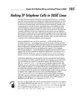
an example Fresnel zone in Figure 13-1.
Water is arguably the most critical aspect. A building’s walls allow the signal
to pass reasonably freely, but objects containing water deflect easily. Trees,
bushes, and people contain water, so keep them out of the Fresnel zone. Line
of sight gives you only a part of the picture — you may set up your antennae
in spring before the trees are full and think that because you can see the
other antenna, it should be okay. It won’t be. Not only will the branches block
the signal, but transmission also worsens as the leaves develop.
234
Part IV: Keeping Your Network on the Air — Administration & Troubleshooting
19_575252 ch13.qxd 9/2/04 4:07 PM Page 234
We show you how to manually calculate the Fresnel zone in your network in
Appendix C. To calculate your particular Fresnel zone, you can go online at
www.zytrax.com/tech/wireless/calc.htm or many other locations and
either use the calculator shown or in the case of this site, download the code
and run it on your own machine. You see an example of the calculator from
this site in Figure 13-2.
Enter the distance between the antennae and then click the Calculate button.
The Web page then shows you the radius of the first Fresnel zone along with
Earth Height and Obstacle Radius.
Figure 13-2:
Example
Fresnel zone
calculator.
Trees blocking part of the Fresnel zone
Fresnel zone
Figure 13-1:
Example
Fresnel
zone.
235
Chapter 13: Problems with Keeping on the Air
19_575252 ch13.qxd 9/2/04 4:07 PM Page 235
What do all these things mean to you? If you have no external antennae, then
it’s probably just interesting reading. However, if you’re trying to connect mul-
tiple locations based on some distance, you need decent line of sight (LOS)
and a clear Fresnel zone. Even when you believe you have a clear LOS, you
might not have a clear Fresnel zone because of those objects that we mention
earlier. Your wireless signals propagate outwards and, of course, not all of
them end up being direct to the other antenna. How much they are deflected
ends up impacting your overall wireless signal. Because those signals not
traveling directly to the receiver are being deflected, when they arrive at the
other end, they create an out-of-phase condition and can result in canceling
out the direct waves. If the distance is long enough (about 5 kilometers or
more), even the curvature of the Earth can have an impact. That is one reason
for using a calculator to determine these factors and then adjusting your
signal accordingly.
How do you adjust the signal? One obvious method is to raise the antennae
so that they are high enough to maintain a clear Fresnel zone. Another method
is to relocate them to achieve the same effect. You might also change the type
of antenna and use one more suited to your particular needs. A final option
(that we would really disagree with it) is to cut down any trees that may inter-
fere. Naturally, this should be a last resort and should be done in accordance
with any laws in your neighborhood.
All these factors may impact your network and cause you to wring your hands
over troubleshooting problems. In LOS networks, revisit these components
and verify that nothing has changed. Remember that trees grow — and what
worked last year may no longer work because of a now-taller tree. Also, trees
in general are tricky objects, as we already mention. For example, in summer,
they may cause errors in your network but give you no problems in winter.
They may allow your radio waves one day and not the next. It’s best to just
avoid them altogether. You need to also verify that your antennae haven’t
become misaligned because of heavy winds or loose bolts. Maybe ice is cov-
ering them in the winter and causing interference. Maybe the Earth’s bulge
changed and now impacts your line of sight. Okay, not that one, we hope, or we
will all be wishing we’d paid more attention in all those survival-type movies.
Multipath Interference
Perhaps your life is a crossroads, and you have many paths you can choose.
Choose the wrong path, and life may not be as sweet as you’d like it to be.
This is basically what happens with your wireless signals sometimes. It gets
deflected on its journey, and that can cause problems.
236
Part IV: Keeping Your Network on the Air — Administration & Troubleshooting
19_575252 ch13.qxd 9/2/04 4:07 PM Page 236
Multipath propagation is what happens when a radio signal takes different
paths when being sent out from a source (for example, your access point) to
a destination node (for example, the other access point). As the signals travel
toward the other antenna, items get in the way, like walls and doors and equip-
ment, which causes the signal to bounce around in different directions. Some
of the signal may go directly to the destination, and other parts may bounce
from a desk to the ceiling and then on to the destination. As a result of all this,
some of the signal encounters delay and thus travels a longer path to the
receiving access point.
This delay causes the information in the 802.11 signal to overlap, which con-
fuses the receiver. This is often referred to as intersymbol interference (ISI).
If the delays are great enough, bit errors in the packet occur. The receiver can’t
distinguish the symbols and therefore interprets the corresponding bits
incorrectly.
Multipath interference causes downfade, upfade, corruption, and nulling. The
negative effects induced on a WLAN by reflected RF signals arriving at the
receiver along with the main signal.
Delay spread is the difference in time between the main signal and secondary
(reflected) signals arriving (< 4 nanoseconds). This results in
ߜ Decreased signal amplitude (downfade)
ߜ Corruption
ߜ Nulling
ߜ Increased signal amplitude (upfade)
Some multipath solutions include
ߜ Antenna diversity: Antennae on single input
ߜ Switching diversity: Antennae on multiple receivers
ߜ Antenna switching diversity: Antennae on multiple inputs
ߜ Phase diversity: Adjust phase of antenna to phase of signal
ߜ Transmission diversity (used by most WLAN manufacturers):
Transmits from antenna last used for reception
When this happens, the receiving station detects the errors through 802.11’s
error-checking process. The cyclic redundancy check (CRC) checksum that is
always computed will not compute correctly, indicating that errors are in the
packet. In response to those errors, the receiving station will not acknowledge
the source, so eventually, it is retransmitted by the originator. If these retrans-
missions occur too often, they begin to degrade performance, and your users
will be unhappy with their service levels.
237
Chapter 13: Problems with Keeping on the Air
19_575252 ch13.qxd 9/2/04 4:07 PM Page 237
This is more likely to occur in locations with lots of metal objects, such as
factories and warehouses, than in regular office buildings. It is still something
to keep in mind, though, because perhaps your office adjoins a factory and
your signals would bounce on its equipment.
When comparing the different spectrums — frequency hopping spread spec-
trum (FHSS), direct sequence spread spectrum (DSSS), and orthogonal fre-
quency division multiplexing (OFDM) — the most susceptible to multipath
propagation is DSSS, which is the one used in 802.11b networks. FHSS uses
relatively narrow channels (1 MHz) and changes transmit frequency often,
making it difficult for multipath to occur. OFDM (used in the 802.11a and
802.11g spectrums) transmits information on a number of subchannels, which
helps reduce the impacts of multipath for those spectrums. 802.11b systems
then are usually the most susceptible, so moving off those onto the other
types is a potential solution when you are not too heavily involved in 802.11b
equipment.
Another solution may come from the vendors. Palo Alto, Calif based Airgo
Networks (
www.airgonetworks.com) recently unveiled its AGN100 Wi-Fi
chipset, which it indicates will actually use multipath interference to its advan-
tage. This chipset listens in all directions at the same time; by simultaneously
processing all that information, you apparently get a strong signal. We will
have to wait and see whether this works as advertised. It also has the disad-
vantage of needing to be incorporated into all the access points, thus making
it problematic if other vendors don’t buy into it.
You Can’t Go That Far: Free Space Loss
Free space. (There isn’t much that is free these days, is there?) Unfortunately,
loss we can do without. Especially if you’re in a casino reading this book in
between card hands. Free space loss is the power loss of the radio wave trav-
eling through the air with no obstacles impeding it. In other words, it’s the
distance it will travel if let be and nothing tries to impact it. Maybe Star Trek
fans will think that means it will travel into outer space and other galaxies. We
doubt it because the signal just isn’t always that strong.
So how far is far? There really isn’t such a thing as an unimpeded signal
because something always gets in the way, whether a person, tree, building,
weather, or whatever. It is primarily caused by beam divergence, which is the
signal energy spreading over larger areas at increased distances from the
source, much like the beam of a flashlight. There is, though, a correspon-
dence between free space loss in dB and distance. You can find mathematical
models to determine this in Appendix C.
238
Part IV: Keeping Your Network on the Air — Administration & Troubleshooting
19_575252 ch13.qxd 9/2/04 4:07 PM Page 238
The decibel (dB) is the basic unit of measurement used in Wi-Fi radio signals.
The B is in honor of Alexander Graham Bell, who was the inventor responsi-
ble for much of today’s acoustical devices.
The formula for this loss at 2.4 GHz is
FSL = 104.2 + 20 log D
where D = distance in miles.
Example: At 5 miles, FSL is 118 dB.
You can use the following guideline when calculating free space loss: When
you double (or halve) the distance from the transmitter to the receiver, the
signal level lowers (or increases) by 6 dB.
This loss is attenuation, which is simply a reduction of signal strength during
transmission of a signal. The free space loss attenuation needs to be taken
into consideration when designing your network to ensure that your signal
reaches its intended antenna, especially when that distance is large.
As the frequency increases, so too does path loss, meaning that a 2.4 GHz
system has a greater range than that of a 5 GHz system of equal power output
because of its lower frequency. A 2.4 GHz radio signal typically experiences a
free space path loss of about 120 dB over a distance of 5 miles. This isn’t a
problem for indoor setups but is problematic when you’re planning a larger
scale network.
To help counteract this loss, you need to either increase the sensitivity of your
devices or boost the signal with repeaters. All this should be coupled with the
data in your loss budget (see Chapter 2). When you design a network, you start
with output power, add antenna gain, and then subtract loss from your cables
and the free space loss. If the resulting number still exceeds the equipment’s
receiving sensitivity, the signal gets through. We recommend providing for a
margin of error by defining a fade margin of perhaps 20 dB.
Contention-Free Frames
Collisions occur, whether on the highway or on a network. Managing those
collisions is what differentiates the better network. To do that, you need to
use some form of detection with enough smarts to keep the collisions to a
minimum while ensuring that traffic actually passes across the medium in a
timely manner.
239
Chapter 13: Problems with Keeping on the Air
19_575252 ch13.qxd 9/2/04 4:07 PM Page 239
The basic mechanism in use is Distributed Coordination Function (DCF). To use
this mechanism, our wireless networks use Carrier Sense Multiple Access with
Collision Avoidance (CSMA/CA) for managing potential frame collisions. Most
LANs use a similar but different protocol called Carrier Sense Multiple Access
with Collision Detection (CSMA/CD). Wireless cannot use the Collision Detec-
tion method for a couple of reasons, one of which is that the radios would
have to transmit in Full Duplex, which is far more expensive, so they try and
avoid the collision rather than detect it.
When you operate a wireless network, detecting collisions is hard, so CSMA/CA
just tries to avoid them, effectively managing the problem. In CSMA/CA, the
Medium Access Control (MAC) layer uses the Distributed Coordination Function
(DCF) protocol that works as listen-before-you-talk scheme. Too bad more
people don’t use that, isn’t it? Another factor is the Point Coordination Function
(PCF), which is an optional function used to implement time-bounded services,
like voice or video transmission. This Point Coordination Function makes use
of the higher priority that the access point gains by using a smaller Inter Frame
Space (PIFS). By using this higher priority access, the access point issues
polling requests to the stations for data transmission, thereby controlling net-
work access. In order to allow regular stations access to the network, each
access point must leave enough time for Distributed Access in between the
PCF. The following lists some of the key aspects of DCF and PCF.
ߜ Distributed Coordination Function
• All stations contend for access.
• Available with BSS, ESS, and IBSS.
• AP similar to wired hub; used to send data.
ߜ Point Coordination Function
• Contention-free frame transfers.
• Requires an AP, so only BSS and ESS.
• AP polls stations.
Along with that is the clear channel assessment (CCA) algorithm that measures
the RF energy at the antenna and determines the strength of the received
signal, which results in the measured signal Received Signal Strength Indication
(RSSI). The protocol has a threshold rule for the RSSI signal strength; if the
threshold is below a certain level, the MAC layer is given the clear channel
status for data transmission. If it is above the threshold, no clearance is given
for communication. In that case, the station waiting for clearance waits for a
determined length of time and tries again. This timeframe is the DCF Interframe
Space (DIFS) and is used to establish clearance to retransmit. The medium
must remain idle for the DIFS time period or no clearance is given.
240
Part IV: Keeping Your Network on the Air — Administration & Troubleshooting
19_575252 ch13.qxd 9/2/04 4:07 PM Page 240
However, the station cannot remain idle forever, or it would never communi-
cate. Thus, another option is available to allow the station to send frames,
using Request to Send (RTS), Clear to Send (CTS), and acknowledge (ACK)
transmission frames. The station begins by sending a short RTS frame. This
includes the length of the message and the destination. Included is the network
allocation vector (NAV). This NAV is used to alert all other nodes in the net-
works to wait for the duration of transmission. After seeing this NAV frame, the
receiving station sends a Clear To Send frame, echoing the sender’s address
along with the NAV item. If the sender does not receive this CTS frame, it
assumes that a collision occurred and sends another RTS frame, in effect start-
ing over again. If the CTS frame is received, the transmission begins, starting
with an ACK frame for verification. Between two consecutive frames in this
whole sequence, a Short Interframe Space (SIFS; a sort of time-out period)
gives the devices time to respond. These SIFS are shorter than the DIFS period,
giving both the CTS responses and the ACKs the highest priority access across
the network. This does, however, initiate a high level of overhead on the net-
work. You can use the On with Threshold setting for large packets, though,
which should help. Whew! That’s quite a load, and you might want to take a
minute to breathe again.
Collisions still occur, of course, but this hopefully minimizes the number of
collisions, keeping the network running efficiently. Numerous technical man-
uals explain this in more detail, but we hope that this short summary pro-
vides a decent overview of the process. If you’re hungry for more, try the
book by Ramjee Prasad, Werner Mohr, and Walter Konhauser, Third Genera-
tion the Mobile Communication Systems (Artech House). You can also go
to
encyclopedia.thefreedictionary.com/CSMA-CA and read about it
there. Another excellent article can be found at
www.sss-mag.com/pdf/
802_11tut.pdf
.
Hidden Node — So Where Is It?
So now we have nodes that are hiding from us? Yikes! Do they have a life of
their own? No, this is another technical aspect of wireless networking. This
term refers to those nodes or stations that are out of range of the others; this
often occurs with outdoor installations. Of course, it can also happen indoors,
like when you have two workstations separated by an interior wall that causes
the signals to break up, allowing them to hear the access point but not each
other. If we use the example of a typical topology with an access point and a
number of stations nodes surrounding it in a circular fashion, each station
must be in communication range of the access point, or they cannot commu-
nicate. The stations, however, cannot always hear each other’s traffic because
of obstructions like trees or buildings.
241
Chapter 13: Problems with Keeping on the Air
19_575252 ch13.qxd 9/2/04 4:07 PM Page 241
These hidden stations can therefore disrupt network traffic by improperly
sending at times when other nodes are transmitting. This results in interfer-
ence and back-off behavior that reduces network performance. That’s a bad
thing. It’s even more vicious when the network is using things like streaming
video, causing performance to possibly drop by as much as 70 percent. The
collision avoidance mechanisms discussed earlier just aren’t effective in deal-
ing with this problem because they were never designed to handle today’s
continuous data transmissions.
The RTS/CTS method discussed earlier was designed to resolve the hidden
node problem although a paper exists that indicates it doesn’t always fix the
problem. A detailed technical discussion on this appears at
nislab.bu.edu/
sc546/sc546Fall2002/blocknode
where the proponents outline the prob-
lem and possible solutions. This is a time- and bandwidth-consuming process
that is required for every transmission by every wireless node. And appar-
ently, it still doesn’t address the problem because more than one node might
initiate this process at the same time because they cannot hear each other
directly.
So what other solutions exist? It seems that there are mixed messages depend-
ing on vendor implementations. The KarlNet company (
www.karlnet.com)
offers the TurboCell product, which uses a centralized control function at the
access point or base station to help eliminate hidden stations. The TurboCell
access point uses a specially optimized polling technique to tell the wireless
stations when they can transmit. It uses this and a free-for-all technique that
prioritizes the stations to avoid the issue. You’d have to try the product, we’d
guess, to be sure it works for you.
You might also investigate the Wireless Central Coordinated Protocol (WiCCP),
which purports to eliminate the hidden node problem. WiCCP is said to be a
protocol booster for 802.11b wireless networks, providing cyclic token-passing
medium access and also scheduled allocation of the available network
resources to eliminate the hidden node problem. You can find out more at
www.patraswireless.net/software.html. Better yet for those on a budget,
it appears to be a freely available solution.
Finally, you can consider the following:
ߜ Use RTS/CTS to reduce impact.
ߜ Increase station power.
ߜ Remove obstacles.
ߜ Move stations.
242
Part IV: Keeping Your Network on the Air — Administration & Troubleshooting
19_575252 ch13.qxd 9/2/04 4:07 PM Page 242
You also need to consider the Near/Far condition and implement solutions to
it. This occurs with
ߜ Multiple clients nearer to AP with high power settings
ߜ One or more client farther away with lower power setting
Some of the solutions for Near/Far conditions include
ߜ Increase power to remote station.
ߜ Decrease power to local stations.
ߜ Move the remote station closer to the AP.
Managing Power
Ah, power. The aphrodisiac of many people. From politicians to business
people to kings and queens. And now you can find it in wireless networks as
well. But, of course, here we talk about power in the literal sense of electricity,
not those other types of power.
We all know and love the need for power in our laptops and digital assistants.
The more, the better, right? On long plane trips, a two-hour battery just isn’t
that effective anymore. It’s one reason airlines are beginning to slowly add
power outlets to their seats so you can use your device for as long as you
desire. This is handy for us because we often need to finish that chapter or
research the next one while winging merrily away to some foreign realm.
To read more about the realities of electrical power, you can peruse Appendix
C, where we go into excruciating detail for you. Suffice it to know, however, that
increasing the power to your access point might increase the signal strength
and allow you to reach that far point.
The FCC allows only 4 watts of radiated power from an antenna in a point-to-
multipoint wireless LAN connection using unlicensed 2.4 GHz spread-spectrum
equipment, so beware of increasing past this amount.
Your access point will use a certain level of power, typically between 30–100
mW. Changing this increases the potential signal strength and may allow for
that slight extra reach that you are looking for in your access point.
On certain Linksys equipment, you might use SNMP to change the power set-
tings. You can go to
www.pasadena.net/aprf for an interesting article on
doing this yourself. There is a page at
www.personaltelco.net/index.cgi/
AccessPointReviews
showing numerous access points and their power
243
Chapter 13: Problems with Keeping on the Air
19_575252 ch13.qxd 9/2/04 4:07 PM Page 243
ratings that you can use for reference. Some even include whether the power
level is changeable; however, remember that this will probably invalidate any
warranty you might have with the device.
Power over Ethernet (PoE)
Power over Ethernet (PoE) is mentioned elsewhere in this book, but here we
tell you more about what this is and how it works. Some access points can be
powered by using the Ethernet cable that connects the access point to the
wired network. This is typically implemented by using a specialized piece of
equipment in your wiring closet that inputs AC power along with the data
connector from the wired switch, and then outputs DC power over some of
the unused wire pairs in the networking cable that runs between that special
module and your access point. This eliminates any need to run a power cable
to the access point, thus allowing more discretion where it is placed because
there is no need for an outlet nearby.
This is an IEEE 802.3af PoE standard, so it stands up to some scrutiny. The IEEE
began the process in 1999; early players included 3Com, Intel, PowerDsine,
Nortel, Mitel, and National Semiconductor. It was formally approved by the
IEEE Standards Board on June 12, 2003. Using such a mechanism allows for
more freedom in selecting a location that best suits the radiated radio waves,
allowing for optimal access point placement. This is especially useful in old
buildings or locations where running electrical power might be problematic.
Two types of devices are specified in this standard: Power-Sourcing Equipment
(PSE) and Powered Devices (PD). The PSE provides 48v (volt) DC power, with a
current limit of 350 milliampere (mA), to the PD and is limited to a continuous
maximum power output of 15.4 watt (W). Dual-radio wireless access points typ-
ically require around 14 W of power, so there is ample there.
In addition, there needs to be enough cumulative power available to support
all your connected PoE devices. This cumulative power can quickly add up to
a large amount, possibly more than what is being supplied by a standard 110v
AC wall power switch. Large PoE installations therefore may need additional
110 or 220 AC power lines.
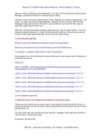
How does it all work then? Power passes from the Power Sourcing Equipment
to your powered device over standard Ethernet CAT-5/6 cables. Ethernet sig-
nals travel along two twisted pairs, one pair for each direction. There are four
twisted pairs in each CAT-5/6 cable. PoE uses one spare pair for the positive
DC supply and the other spare pair for the negative return. Another method
involves actually using a pair of wires that’s already being used to pass data.
Either implementation provides power to the device. You can see how it
works in Figure 13-3.
244
Part IV: Keeping Your Network on the Air — Administration & Troubleshooting
19_575252 ch13.qxd 9/2/04 4:07 PM Page 244
This is really useful for only those sites that require it because it does add
complexity — when you add complexity, things can break or be more difficult
to manage. If you plan to purchase and use such a facility, be sure to visit
www.poweroverethernet.com and read all about it in detail before jumping
into something you may regret later.
Calculating your Power Budget
Your Power Budget is the total power output from your wireless system and is
also the sum of the following items:
ߜ Radio transmit power
ߜ Cable and connector losses
ߜ Antenna gain
Put these into a calculator (
www.zytrax.com/tech/wireless/calc.htm)
with the correct figures, and you have the budget for your installation. The
fundamental aim of your radio link is to deliver sufficient signal power to the
Ethernet switch
Power over Ethernet
midspan hub
Wireless
access point
Wireless
access point
Figure 13-3:
An example
PoE
installation.
245
Chapter 13: Problems with Keeping on the Air
19_575252 ch13.qxd 9/2/04 4:07 PM Page 245
receiver in order to achieve a performance objective. This objective is typi-
cally specified as a minimum bit error rate. Configuring your power budget
allows this rate to be optimal. You can find a hugely scientific primer on this at
wireless.ictp.trieste.it/school_2004/lectures/carlo/linkloss,
but beware that it is not for the faint of heart.
Managing the available power in your wiring closet might also be a challenge.
Each port adds 15.4 watts to the total power required. This adds up quickly
in larger installations. A small wiring closet supporting 100 PoE users needs
to deliver up to 1,540 watts of power simultaneously to those users. Add this
to the 1,000 watts that the average switch requires, and your 2,540 W switch
will need 23-amp service.
That can easily be a problem for many wiring closets. In most buildings, elec-
tricity is rated for only 15- or 20-amp service. Many LAN switches support
240–360 ports in a single chassis, requiring 35- to 50-amp service to support
PoE fully on each port. You will need a lot more power into the closet than
you might have originally planned to use. You might want to make sure that if
you’re constructing a facility with PoE, multiple 20-amp circuits and/or 220v
service are available.
Those of you with Cisco devices can use the Cisco Discovery Protocol (CDP),
which is used to specify the exact power requirements of each device after
initial power has been placed on the line. When using this proprietary method,
Cisco says that it can power more devices with the same power budget, which
might be a big help in those large installations.
The following lists some of the things to look for when purchasing PoE
equipment:
ߜ Do the Power Sourcing Equipment (PSE) and Powered Devices support
power classification?
ߜ What is the maximum wattage the system can deliver?
ߜ How much power will the PSE draw from the wall?
ߜ How does the PSE deal with a loss of power from a failed power supply?
ߜ Will you need special power provisions in your wiring closet to support
the PoE switch port density you require?
After you implement a Power over Ethernet infrastructure and are happy with
it, you may want to think about power surge protection. The Citel Inc. company
(
www.citelprotection.com) has designed surge protection that prevents
electrical damage over PoE installations. Its MJ8-505-24D3A60 product features
a circuit that isolates data from Ethernet power lines, protecting all eight pins.
The clamping response of this product apparently permanently eliminates tran-
sients, ensuring equipment safety and optimal data transfer.
246
Part IV: Keeping Your Network on the Air — Administration & Troubleshooting
19_575252 ch13.qxd 9/2/04 4:07 PM Page 246
Another vendor, smartBridges (www.smartbridges.com/web/products/po.
asp
), has introduced its PoE Outdoor product, which is a unique Power over
Ethernet device for outdoor wireless installations. This has NEC-compliant
surge protection and weatherproof durability, so it offers some pretty impres-
sive-sounding capabilities.
On a smaller scale, the Injector product is a passive device that gates the
power jack onto the Ethernet connection and is used to inject power onto the
Ethernet cable. The box has two RJ-45 jacks: One has power, and the second
has only Ethernet connections.
The Injector has voltage surge protection on the Ethernet-only side of the
injector, and also surge protects the power lines, shunting any surges to the
ground side of the power jack. It can handle an 800v surge and 1500 W burst,
thus providing some degree of protection against these scourges of all power
installations.
Many new product lines are being introduced with PoE capability. You’ll need
to contact your favorite vendor for the latest details.
247
Chapter 13: Problems with Keeping on the Air
19_575252 ch13.qxd 9/2/04 4:07 PM Page 247
248
Part IV: Keeping Your Network on the Air — Administration & Troubleshooting
19_575252 ch13.qxd 9/2/04 4:07 PM Page 248
Chapter 14
Bridging Networks to
Manage Coverage
In This Chapter
ᮣ Using your site survey
ᮣ Understanding bridges, switches, and routers
ᮣ Wireless bridges defined
ᮣ Building wireless bridges
ᮣ Building software bridges
ᮣ Troubleshooting your network
ᮣ Using wireless switches
B
eing able to network devices without the need for cabling is a major
boon for small and medium businesses alike. Although large enterprises
flood wire to make their office buildings network-ready, anyone setting up a
small or medium business is unlikely to have the same luxury. For one thing,
you may not want to go through the hassle of wiring up your office if you don’t
own the building — you may move on to new premises when the business
takes off.
As a tenant, you may not have sufficient space on one floor or in one building
to house all your employees. In the not-so-distant past, you had to call your
Regional Bell Operating Company (RBOC) and get them to install a leased line
to join your networks in the two buildings. Or you had to get the landlord to
agree to let you run wire from one floor to another. This represented a large
outlay and commitment of money for a small or start-up organization. You
could use an on-demand service such as dial-up, but you won’t get the through-
put you need.
You are ready to extend your network beyond your indoor LANs. Perhaps
you are fed up with the high recurring costs associated with leased lines or
the expense that comes with running fibre underground, especially in areas
20_575252 ch14.qxd 9/2/04 4:08 PM Page 249