Topology Control in Wireless Ad Hoc and Sensor Networks phần 6 potx
Bạn đang xem bản rút gọn của tài liệu. Xem và tải ngay bản đầy đủ của tài liệu tại đây (392.42 KB, 28 trang )
112 LOCATION-BASED TOPOLOGY CONTROL
of this issue), the authors of (Li et al. 2003) propose two techniques for avoiding this
inconvenience: (i) enforcing all unidirectional links in G
LMST
to become bidirectional; or
(ii) deleting all the unidirectional links in G
LMST
. If technique (i) is used, the obtained
graph is the symmetric supergraph of the original topology, which is denoted as G
+
LMST
;if
technique (ii) is used, we obtain the symmetric subgraph of the original topology, which
we call G
−
LMST
.
Note that which one of the G
+
LMST
and the G
−
LMST
topology is to be preferred depends
on the application scenario: the former topology is relatively dense, and it thus keeps more
routing redundancy, which is useful to balance the traffic load and to improve fault tolerance;
the latter topology is very sparse, and it should be used when the expected network traffic
is quite low.
To convert G
LMST
into either G
+
LMST
or G
−
LMST
, each node u afterPhase3ofthe
algorithm probes all the nodes in N(u) to find out whether the corresponding link is uni-
directional. In case it is, the link is either removed (technique (ii)), or the neighbor node
is notified to add the reverse edge (technique (i)). Note that in case the probed link (u, v)
is unidirectional node u is not in N(v), so node v does not know which transmit power to
use to the send the reply message to u. This problem can be easily solved by piggybacking
the transmit power mp
v
used by u to send the probe message in the message itself. Given
the assumption of symmetric wireless medium, using power mp
v
is sufficient for node v to
reach node u.
Protocol LMST is summarized in Figure 10.7.
10.2.2 Protocol analysis
In (Li et al. 2003) it is proven that the topology produced by LMST has the following
properties:
1. it preserves connectivity in the worst case;
2. it has maximal logical node degree equal to 6;
3. it can be computed in a fully distributed and localized fashion; in particular, computing
G
LMST
requires sending only n messages overall (n is the number of network nodes).
Properties (1) and (2) are satisfied also by the symmetric variants of G
LMST
, G
+
LMST
and G
−
LMST
. As for the message complexity, computing both G
+
LMST
and G
−
LMST
requires
exchanging O(n
2
) messages overall (at most n − 1 probe messages are sent by a node in
Phase 4 of the protocol).
Note that the upper bound stated in (2) is on the number of logical neighbors; it is easy
to find worst-case scenarios in which the physical degree of a node in G
LMST
is arbitrarily
high (this is implied by Theorem 9.3.3).
The authors of (Li et al. 2003) have also evaluated the average-case performance of
LMST on random node deployments through simulation, and they have verified that LMST
produces topologies with a smaller average logical node degree and average transmission
radius with respect to those generated by R&M and CBTC.
LOCATION-BASED TOPOLOGY CONTROL 113
Algorithm LMST:
(algorithm for node u)
VN
u
is the visible neighborhood of node u
N(u) is the neighbor set of node u
bp
u
is the broadcast power of node u
(x
u
,y
u
) are the coordinates of node u
1. Information exchange
send beacon (u, (x
u
,y
u
)) at maximum power
upon receiving beacon (v, (x
v
,y
v
)), store the received power of this message in rp
v
2. Topology construction (after all beacons have been received)
build the local MST on nodes in VN
u
using Prim’s algorithm
let T
u
= (VN
u
,E
u
) be this local MST
N(u) ={v ∈ VN
u
|(u, v) ∈ E
u
}
3. Determination of transmit power
for each v ∈ N(u)
compute the minimum power mp
v
needed to reach v based on rp
v
bp
u
= max
v∈N(u)
mp
v
4. (Optional) Topology with bidirectional links
for each v ∈ N(u)
send probe message (u, mp
v
) to v using power mp
v
upon receiving reply message (v, state) from v
if state = uni then
notify v sending message (u, add) (technique 1)) using power mp
v
or
delete v from N(u) (technique (2))
upon receiving probe message (v, mp
u
)
if v ∈ N(u) then
send reply message (u, bi) using power mp
u
otherwise
send reply message (u, uni) using power mp
u
upon receiving notify message (v, add)
add node v to N(u), with associated power mp
v
if necessary, update the broadcast power bp
u
Figure 10.7 The LMST protocol.
114 LOCATION-BASED TOPOLOGY CONTROL
10.2.3 The FLSS
k
protocol
Some of the authors of (Li et al. 2003) have presented a variation of the LMST algorithm
aimed at improving the fault tolerance of the constructed topology. In particular, the design
goal is to build an energy-efficient topology that preserves k-connectivity (provided the
maxpower communication graph is k-connected), where k is a small constant (typically,
2–3). The resulting protocol, presented in (Li and Hou 2004), is called FLSS
k
(Fault-tolerant
Local Spanning Subgraph).
Similarly to LMST,FLSS
k
is composed of three phases: information exchange, topology
construction, and determination of transmit power. The information exchange phase is iden-
tical to that of LMST: every node broadcasts its ID and position at maximum power, and
collects the location information sent by its visible neighbors. The main difference between
LMST and FLSS
k
is in the topology construction phase: instead of building a local MST
on the set of its visible neighbors, a node u builds a spanning subgraph G
u
that preserves
k-connectivity on the same set of nodes (see (Li and Hou 2004) for details). Then, node
u selects its immediate neighbors in the G
u
graph as logical neighbors that are retained in
the final topology. The last phase of the protocol (determination of transmit power) is the
same as in LMST.
Similar to LMST, the topology built by FLSS
k
might contain unidirectional links, and
symmetry can be enforced by either removing all the unidirectional links or by making them
bidirectional.
Li and Hou prove that FLSS
k
(and its symmetric variants) preserves k-connectivity, and
that it minimizes the maximum transmitting range of nodes in the network over all localized
algorithms. Furthermore, Li and Hou investigate the average-case performance of FLSS
k
through simulation, whose results show that FLSS
k
is more energy efficient than other
existing localized fault-tolerant topology control protocols, such as the k-UPVCS algorithm
introduced in (Hajiaghayi et al. 2003) and the k-connected variation of CBTC introduced
in (Bahramgiri et al. 2002).
11
Direction-based Topology Control
In this chapter, we consider topology control protocols that rely on the ability of the nodes to
estimate the relative direction of their neighbors. This is relatively less accurate information
than knowing exact node locations, as the former type of information can be determined if
the latter is known, but not vice versa.
Several techniques for estimating the direction from which a certain node is transmitting
have been proposed and discussed in the IEEE Antenna and Propagation community (IEEE
2004). This problem is known as the Angle-of-Arrival (AoA) problem, and it is typically
solved by equipping nodes with more than one directional antenna (Krizman et al. 1997). So,
in the case of directional information also, some extra hardware on the nodes (with respect
to the standard assumption of nodes equipped with a single, omnidirectional antenna) is
needed in order to provide the requested information. An advantage of using AoA-based
techniques instead of location-based techniques is that the AoA can be accurately estimated
in indoor environments also.
Despite the relatively less accurate information used, direction-based topology control
protocols can produce almost as good topologies as in the case of location-based topol-
ogy control. In particular, fully distributed, localized protocols that preserve worst-case
connectivity can be designed in this setting also.
In the remainder of this chapter, we present two location-based topology control pro-
tocols: the CBTC protocol introduced in (Wattenhofer et al. 2001) and further analyzed in
(Li et al. 2001) and the DistRNG protocol presented in (Borbash and Jennings 2002).
11.1 The CBTC Protocol
The CBTC (Cone-based Topology Control) protocol (Li et al. 2001; Wattenhofer et al. 2001)
is based on the following idea: set the transmit power level of node u to the minimum value
p
u,ρ
such that u can reach at least one node in every cone of width ρ centered at u (see
Figure 11.1). In other words, a node must retain connections to at least one neighbor in
‘every direction’, where parameter ρ determines the granularity of what is meant by ‘every
direction’.
Topology Control in Wireless Ad Hoc and Sensor Networks P. Santi
2005 John Wiley & Sons, Ltd
116 DIRECTION-BASED TOPOLOGY CONTROL
u
v
w
z
r
Figure 11.1 Intuition behind the CBTC protocol: node u sets its power level to the minimum
value p
u,ρ
such that it can reach at least one node in every cone of width ρ centered at
itself. In the example above, ρ =
π
2
, and node u must use a transmit power level at least
sufficient to reach node v. If a lower power is used, the angular gap between u’s neighbors
would be >
π
2
(see nodes w and z), and the condition that every cone of width
π
2
centered
at u contains at least one neighbor would be violated.
Note that the idea behind CBTC is very similar to that used in the definition of the Yao
Graph (see Appendix A). We recall that the Yao Graph of parameter c (for some integer
c ≥ 6), denoted YG
c
, is defined as follows: at each node u, divide the plane into c equally
separated cones centered at u; then, connect u to its closest neighbor within each cone. The
difference between YG
c
and the topology generated by CBTC is depicted in Figure 11.2.
In order to make the two graphs as much similar as possible, we set c = 6andρ =
π
3
.In
YG
6
, the cones are predefined, and it is sufficient to reach one neighbor in each such cone.
On the contrary, in CBTC, it is required that the angular gap between any two neighbors
of u is at most ρ; in other words, when a cone of width ρ centered at u sweeps the plane,
it must always contain at least one neighbor. This is a stronger requirement than in case of
YG
6
, as shown in Figure 11.2.
We now present the distributed implementation of CBTC, and then we discuss its prop-
erties. Finally, we describe some of the variations of CBTC that have appeared in the
literature.
11.1.1 The basic CBTC protocol
The CBTC protocol is composed of two phases: in the first phase (basic protocol), every
node u determines the minimum power p
u,ρ
needed to reach a neighbor in ‘every direction’
as described above; then, network nodes exchange additional information to identify energy-
inefficient edges, which are removed from the final topology.
DIRECTION-BASED TOPOLOGY CONTROL 117
u
v
w
z
Figure 11.2 Difference between YG
6
and the topology generated by CBTC with parameter
ρ =
π
3
. The dotted lines define the six cones used in the definition of YG
6
; node u must
use sufficient transmit power to reach the closest neighbor in each cone, which corresponds
to the power needed to reach node w (dotted circle). However, using this transmit power
is not sufficient to fulfill CBTC’s condition: there exists a cone of width
π
3
that contains
no node (see the angular gap between nodes w and z). To fill this gap, u’s transmit power
level must be increased to reach node v also (solid circle).
CBTC uses two types of messages: beacon messages, which are sent at a certain power
p ≤ P
max
(P
max
denotes the maximum nodes’ transmit power, which is assumed to be the
same for all the nodes) and received by all the nodes that are within u’s range with power
p;andacknowledgment messages (Ack for short), which are sent in response to beacons
and are received only by the node that originated the beacon.
The beacon message contains the node ID and the power p used to send the message;
the Ack message contains the ID of the sender, the ID of the intended receiver (the node
that originated the beacon), and the power used to transmit the message. Inclusion of the
transmit power in the messages is needed to identify energy-inefficient links in Phase 2 of
the protocol.
The first phase of CBTC is as follows. Initially, node u sends the beacon at power p
0
and collects the Ack messages sent by the nodes that received the beacon. When receiving
an Ack message, node u stores the identity of the new neighbor and determines its relative
direction. As discussed at the beginning of this chapter, this is made possible by the use of
AoA estimation techniques, such as using multiple directional antennas. The Ack messages
are sent using the same power level used to send the originating beacon message. This way,
under the common assumption of symmetric wireless medium, we can ensure that node
u eventually receives the acknowledgments from all the nodes that received its beacon.
After all the Acks for power level p
0
have been collected, node u invokes the CheckGap
procedure, which verifies whether the condition on the angular gap between neighbors is
met. If the condition is not satisfied, node u invokes the procedure IncPower, which increases
the transmit power level to the next level p
1
. Then, it sends a new beacon message, waits
118 DIRECTION-BASED TOPOLOGY CONTROL
Algorithm basicCBTC:
(algorithm for node u)
ρ is the required angular gap between neighbors (input parameter)
p(u) is the current transmit power level of node u
N(u) is the neighbor set of node u
D(u) is the set of u’s neighbor directions
CheckGap(ρ, D(u)) is the procedure that checks whether the CBTC condition with
parameter ρ is satisfied. It returns True if it is satisfied, False
otherwise
IncPower(p) is the procedure that, given the current transmit power p, returns the next
transmit power level
1. Initialization
N(u) =∅
D(u) =∅
p(u) = 0
2a. Computing power p
u,ρ
repeat until CheckGap(ρ, D(u)) = True or (p(u) = P
max
)
p(u) = IncPower(p(u))
send beacon (u, p(u)) at power p(u)
repeat until all Acks have been received
receive Ack (v, u, p(v)) from node v
N(u) = N(u) ∪{v}
update direction set D(u) including v’s direction
2b. Sending Ack message
upon receiving beacon (v, p(v)) from v
check if this is the first beacon received from v
if yes send Ack (u, v, p(v)) at power p(v), otherwise ignore the beacon
3. Finalization
p
u,ρ
= p(u)
Figure 11.3 The basicCBTC protocol.
for the Acks, and so on. This algorithm is repeated until either the condition on the angular
gap between neighbors is satisfied or p
i
= P
max
.Phase1ofCBTC (also called basicCBTC)
is summarized in Figure 11.3.
Note that the following optimization, called the shrink back operation, can be easily
implemented. At the end of basicCBTC’s execution, a node sets its transmit power at the
DIRECTION-BASED TOPOLOGY CONTROL 119
maximum level if the condition on cone coverage cannot be satisfied. We call such nodes
boundary nodes. The shrink back operation is executed at boundary nodes only, with the
purpose of reducing the broadcast power p
u,ρ
without reducing the cone coverage. More
specifically, basicCBTC is modified in such a way that, at each iteration, a node in N(u)
is tagged with the power used the first time it was discovered. Suppose the power levels
used during the neighbor discovery phase are p
0
,p
1
, ,p
k
= P
max
, and let CC
i
be the
cone coverage provided by the neighbors at level i.IfCC
k
< 2π, the broadcast power level
p
u,ρ
is reduced to the minimum level p
i
such that CC
i
= CC
k
. Note that tagging each
neighbor with the minimum power needed to reach it is useful for implementing another
optimization also: if u must send a packet to a certain neighbor v that can be reached with
power p
i
<p
u,ρ
, it can send the packet using power p
i
instead of the broadcast power.
11.1.2 Dealing with asymmetric links
Let us denote with G
ρ
CBTC
the graph obtained after basicCBTC’s execution with parameter
ρ, that is, the graph that contains the directed link (u, v) if and only if v ∈ N(u) at the
end of the protocol. The example reported in Figure 11.4 shows that the neighbor relation
induced by basicCBTC is not symmetric, that is, G
ρ
CBTC
can contain unidirectional links.
Suppose ρ is set to
2
3
π.AttheendofbasicCBTC’s execution, node u sets its transmit
power to the minimum level p
u,
2
3
π
needed to reach the three neighbors at distance d.Since
the distance between u and v is greater than d, there is no direct link between u and v.
On the other hand, node v has u in its neighbor list at the end of the protocol. In fact, if
v would use a lower power than the minimum power p
v,
2
3
π
needed to reach u, the angular
gap between its neighbors would be greater than
2
3
π (see the gap between nodes w and z).
So, the directed link (v, u) is part of the final topology, while the reverse link is not.
Since, as discussed in several parts of this book, having a topology with symmetric links
is desirable, the authors of (Li et al. 2001; Wattenhofer et al. 2001) propose two techniques
to address unidirectional connections: (i) augmentation and (ii) asymmetric edge removal.
u
v
w
z
d
Figure 11.4 Example of asymmetric link with basicCBTC. The parameter ρ is set to
2
3
π.
120 DIRECTION-BASED TOPOLOGY CONTROL
In (i), every asymmetric link (u, v) is made symmetric by adding the reverse edge
(v, u) in the graph.
1
To implement this strategy, it is sufficient that every node u at the end
of basicCBTC advertises its neighbor set at the broadcast power p
u,ρ
. Upon receiving the
neighbor set from v, node u verifies whether v ∈ N(u); if yes, no action is taken; otherwise,
v is included in N(u),andu’s broadcast power is increased consequently (if necessary). In
the following, we will call this version of CBTC as AugmCBTC, and we will denote the
corresponding topology with G
ρ,+
CBTC
.
In (ii), asymmetric links are removed from the final topology as follows.
2
After finishing
basicCBTC, a node u sends a message to each node v/∈ N(u) to which it sent an Ack,
telling v to remove u from N(v). As a consequence of this action, the broadcast power
p
v,ρ
of node v might be reduced. In the following, we will call this version of CBTC as
RemCBTC, and we will denote the corresponding topology with G
ρ,−
CBTC
.
11.1.3 Protocol analysis
The following theorems have been proven in (Li et al. 2001).
Theorem 11.1.1 (Li et al. 2001) Let G be the maxpower communication graph, and assume
G is connected. Let G
ρ,+
CBTC
be the topology generated by AUGMCBTC. Then G
ρ,+
CBTC
is (worst-
case) connected if and only if ρ ≤
5
6
π.
In words, Theorem 11.1.1 states that, if ρ ≤
5
6
π and the maxpower graph G is connected,
then the topology remains connected after AugmCBTC’s execution. On the other hand, if
ρ>
5
6
π, there exists a node placement such that G is connected, but G
ρ,+
CBTC
is not connected.
An example of such node placement is reported in (Li et al. 2001).
Theorem 11.1.2 (Li et al. 2001) Let G be the maxpower communication graph, and assume
G is connected. Let G
ρ,−
CBTC
be the topology generated by REMCBTC. If ρ ≤
2
3
π, then G
ρ,−
CBTC
is (worst-case) connected.
In words, Theorem 11.1.2 states that, as long as ρ ≤
2
3
π, removing asymmetric links
does not compromise network connectivity.
Note that there is a trade-off between using AugmCBTC with ρ =
5
6
π and using Rem-
CBTC with ρ =
2
3
π. After the execution of the basic protocol, the broadcast power level
of node u with ρ =
5
6
π is lower than or equal to the power level with ρ =
2
3
π (because
of the less stringent requirement on cone coverage). However, with augmentation, the final
level used by node u might be increased with respect to the value calculated by the basic
algorithm (this happens if u must reach node v such that u ∈ N(v) but v/∈ N(u)). On the
other hand, with asymmetric link removal, the final level used by u might be decreased
with respect to the value calculated by the basic algorithm (this is because some of the links
incident into u might have been removed). So, which one of the two symmetric versions
of CBTC performs better is not clear. The experimental results reported in (Li et al. 2001)
show that RemCBTC performs slightly better than AugmCBTC in case of random node
deployment.
1
This corresponds to computing the symmetric supergraph of G
ρ
CBTC
.
2
This corresponds to computing the symmetric subgraph of G
ρ
CBTC
.
DIRECTION-BASED TOPOLOGY CONTROL 121
11.1.4 Removing energy-inefficient links
A final optimization phase can be applied to both the symmetric versions of CBTC, with the
purpose of further reducing the transmission power of each node. This optimization requires
that nodes have the ability to perform some sort of distance estimation. In particular, for any
pair v, w of u’s neighbors, node u must be able to determine which one of them is closer.
This can be accomplished by comparing the transmit powers included in the incoming
messages received from v and w (we recall that this information is included in both beacon
and Ack messages) with the reception powers of the messages.
The goal of this optimization stage is to identify energy-inefficient links, which can be
removed without impairing network connectivity. These are called redundant edges,and
are defined as follows:
Definition 11.1.3 (Redundant edge) Let v, w be neighbors of u in the final topology, and
assume that δ(v, w) < max{δ(u,v),δ(u,w)}. Then, the longer of the edges (u, v) and (u, w)
is redundant.
In (Li et al. 2001), it is shown that redundant edges can be removed from the final
topology without impairing network connectivity. However, removing too many edges from
the final topology might be a disadvantage because, for instance, the paths between nodes
would become too long. Since CBTC ’s goal is to reduce the average transmit power of
the nodes, the choice is then to remove only redundant edges with length greater than the
longest nonredundant edge.
11.1.5 Discussion
The CBTC protocol enjoys several nice features: it is fully distributed, localized, preserves
network connectivity, and requires only directional information. This explains the popularity
of CBTC, which is probably the most famous topology control protocol. However, CBTC
has a weak point, namely, the relatively high number of messages that must be exchanged
to compute the network topology.
The reasons for this relatively high message overhead are three: (i) the beacon-Ack mes-
sage exchange needed to estimate neighbor directions; (ii) the mechanism used to discover
new neighbors, based on sending beacons with increasing transmit power; and (iii) the fur-
ther message exchange needed to render the final topology symmetric. In particular, the
choice of the power increase strategy in basicCBTC (the IncPower procedure) is quite
critical: on the one hand, starting with a very low transmit power p
0
and increasing the
power level at each step by a small quantity ε might cause the sending of an excessive
number of beacon messages; on the other hand, if the power levels used for beaconing are
very few, then the number of new neighbors discovered at each step is high, resulting in
computing of a very rough estimate of the broadcast power p
u,ρ
. The choice of the better
power increase strategy is scenario dependent: if the expected node density is very high,
performing a very accurate neighbor discovery (i.e. using many different power levels for
beaconing) is probably the right choice; on the contrary, if the expected density is low,
using relatively few power levels for beaconing is preferable.
122 DIRECTION-BASED TOPOLOGY CONTROL
11.1.6 CBTC variants
Several variants of the CBTC protocol have been proposed recently. In particular, in
(Bahramgiri et al. 2002), Bahramgiri et al. discuss the conditions under which CBTC ensures
k-connectivity. They prove the following theorem:
Theorem 11.1.4 (Bahramgiri et al. 2002) Let G be the maxpower communication graph,
and assume G is k-connected, for some constant k>0.LetG
ρ,−
CBTC
be the topology generated
by R
EMCBTC. If ρ ≤
2π
3k
, then G
ρ,−
CBTC
is (worst-case) k-connected.
Furthermore, they discuss necessary conditions for achieving k-connectivity with Rem-
CBTC. Finally, they introduce a three-dimensional version of CBTC, in which the notion
of coverage is extended to three-dimensional cones.
Another variation of CBTC has been presented in (Huang et al. 2002), where Huang
et al. introduce an implementation of CBTC based on the use of directional antennas. In fact,
it must be noted that although CBTC requires the use of directional antennas to estimate
AoA these antennas are not used to exchange messages: all the communications in the
original CBTC protocol are performed using omnidirectional antennas. On the contrary, the
protocol introduced in (Huang et al. 2002) makes explicit use of directional antennas: the
plane is divided into sectors (corresponding to the possible orientations of the antenna), and
the minimum powers needed to reach at least one neighbor in each sector are computed.
Note that this is indeed a distributed computation of the Yao Graph (for a discussion of
CBTC and Yao Graph see above).
11.2 The DistRNG Protocol
The DistRNG introduced in (Borbash and Jennings 2002) is a distributed implementation
of the computation of the Relative Neighborhood Graph (RNG), which is defined as follows
(see also Appendix A):
Definition 11.2.1 (Relative neighborhood graph) Let N be a set of points in the Euclidean
two-dimensional space. The Relative Neighborhood Graph of N, denoted by RNG(N), has an
edge between two nodes u and v if there is no node w ∈ N such that max{δ(u,w),δ(v,w)}≤
δ(u,v).
Let Lune(u, v) denote the intersection of the circles of radius δ(u,v) centered at u and
v, respectively. Intuitively, edge (u, v) belongs to RNG(N ) if and only if no other node
in N lays in Lune(u, v) (see Figure 11.5). Note that, contrary to the case of CBTC,the
neighbor relation in RNG is symmetric.
The RNG topology has several interesting features, as evidenced by the simulation-based
investigation on random node deployments reported in (Borbash and Jennings 2002). The
authors considers several aspects of the generated topology
– average logical node degree;
– hop diameter;
– maximum and average node transmitting range;
DIRECTION-BASED TOPOLOGY CONTROL 123
vu
Figure 11.5 Definition of RNG(N ): edge (u, v) is in RNG(N ) if and only if Lune(u, v)
(shaded area) contains no other node in N .
– connectivity;
– size of the largest biconnected component.
Intuitively, a good topology is one in which nodes have low degree, the hop-diameter is
close to the one of the maxpower communication graph, the nodes have small transmitting
range, and connectivity (possibly, also biconnectivity) is ensured. Clearly, identifying a
topology that satisfies all these goals at the same time is virtually impossible, as many of
them are conflicting with each other. The objective is then to build a topology that is a good
compromise between the above goals. To identify such topology, Borbash and Jennings
performed extensive simulation on random node deployments, measuring the above listed
parameters for the following topologies: the MST,theRNG, and the minR graph, which
is obtained by finding the smallest common transmitting range such that connectivity is
achieved (i.e. the CTR), and connecting the nodes consequently.
The simulation-based investigation has shown the following:
– Logical node degree: Both MST and RNG have small average node degree indepen-
dently of the number n of network nodes, while the node degree in minR increases
with n.
– Hop diameter : minR has the smallest hop-diameter and MST the largest, while RNG
is in between the two.
– Transmitting range: MST has the smallest average transmitting range, while minR has
the largest such range. The average transmitting range with RNG is very close to that
with MST.
– Biconnectivity:
3
the minR graph is biconnected in all the simulated scenarios; the RNG
topology has more than 85% of the nodes in the largest biconnected component; MST
is a tree, so it cannot ensure biconnectivity.
3
Note that connectivity is not an issue since, assuming the maximum transmit power is high enough, all the
three topologies considered preserve connectivity in the worst case.
124 DIRECTION-BASED TOPOLOGY CONTROL
Overall, the results of the simulation-based analysis show that RNG is a good com-
promise between the goals listed above: it has relatively low logical node degree, its hop
diameter is not too larger than that of the maxpower communication graph, the average node
transmitting range is quite low, and a good percentage of network nodes are biconnected.
Motivated by this observation, Borbash and Jennings present a protocol, called DistRNG,
for computing the RNG in a fully distributed and localized fashion.
Before introducing the protocol, we need the following notion of neighbor coverage:
Definition 11.2.2 (Neighbor coverage) Consider a network node u, and one of its neigh-
bors v. The neighbor coverage of node v, denoted by Cov
u
(v), is defined as the cone centered
at u that spans Lune(u, v), that is, the cone of width
aub, where a and b are the intersection
points of the circumferences of radius δ(u,v) centered at u and v, respectively. The covered
region of node u is the union set of the coverage of all its neighbors.
The concepts of neighbor coverage and covered region are illustrated in Figure 11.6.
The DistRNG protocol is reported in Figure 11.7. The protocol is composed of a
sequence of neighbor discovery phases: initially, node u grows its transmit power level
until a new neighbor v is discovered; then it adds v to its neighbor set, updates the covered
region, and checks whether the entire 2π span is covered. If not, it increases the transmit
power until a new neighbor in the not-yet-covered region is identified, and repeats the oper-
ations above. This procedure is repeated until the condition on coverage is satisfied or the
maximum transmit power is reached.
v
u
a
b
w
Figure 11.6 The neighbor coverage of node v is defined as the cone of width
aub centered
at u. The covered region of node u (shaded area) is the union set of the neighbor coverages
of nodes v and w.
DIRECTION-BASED TOPOLOGY CONTROL 125
Algorithm DistRNG:
(algorithm for node u)
p(u) is the current transmit power level of node u
P
max
is the maximum nodes transmit power
N(u) is the neighbor set of node u
CR(u) is the covered region of node u
NYCR(u) is the not-yet-covered region of node u
1. Initialization
N(u) =∅
CR(u) =∅
NYCR(u) = 2π
p(u) = 0
2. Computing RNG
repeat until (CR(u) = 2π) or (p(u) = P
max
)
increase p(u) until a new neighbor v in NYCR(u) is discovered
N(u) = N(u) ∪{v}
CR(u) = CR(u) ∪Cov
u
(v)
NYCR(u) = NYCR(u) − Cov
u
(v)
3. Finalization
N(u) is the neighbor set of node u in the final topology
Figure 11.7 The DistRNG protocol.
In (Borbash and Jennings 2002), it is proven that the protocol reported in Figure 11.7
correctly computes the RNG. As in the case of CBTC, the message complexity of the
protocol has not been formally analyzed nor discussed. In particular, in DistRNG also the
strategy used to increase the transmit power in the various neighbor discovery phases has a
critical impact on the number of messages exchanged during DistRNG’s execution.
12
Neighbor-based Topology Control
In this chapter, we consider topology control protocols that rely on the nodes’ ability to
determine the number and identity of neighbors within the maximum transmitting range and
to build an order on this neighbor set (based, for instance, on distance or on link quality).
In a certain sense, this is the minimum amount of information needed by the nodes to build
the network topology: if a node is not able to identify its neighbors, it has no clue on how
to set its transmit power level. The only possible way of setting the transmit power level
in this no-deterministic-knowledge scenario would be to set it at random. In this case, the
amount of knowledge available to the node is represented by the probability distribution
used to set the transmit power level.
In the first part of this chapter, we approach the neighbor-based topology control problem
from a theoretical viewpoint, assuming that every node in the network is connected to its
k closest neighbors. More particularly, we study necessary and sufficient conditions on k
for generating a topology that is connected with high probability (w.h.p.). Then, we present
the KNeigh protocol introduced in (Blough et al. 2003b), which is an implementation of
the above-described topology control technique based on distance estimation. Finally, we
present the XTC protocol introduced in (Wattenhofer and Zollinger 2004), which is based
on a more general notion of neighbor ordering, that is, link quality.
12.1 The Number of Neighbors for Connectivity
In this section, we investigate the following theoretical problem, which has been first studied
in (Xue and Kumar 2004). Before introducing the problem, we need some preliminary
definitions.
Definition 12.1.1 (K-neighbors graph) Let N be a set of nodes deployed in a certain region
R, with |N|=n. Given any k, with 0 <k≤ n − 1,thek-neighbors graph built on N , denoted
by G
k
= (N, E
k
), is the directed graph obtained connecting each node to its k closest neigh-
bors. Formally, the directed edge (u, v) ∈ E
k
if and only if δ(u,v) ≤ d
k
(u),whered
k
(u) is
the distance between node u and its k-closest neighbor.
Topology Control in Wireless Ad Hoc and Sensor Networks P. Santi
2005 John Wiley & Sons, Ltd
128 NEIGHBOR-BASED TOPOLOGY CONTROL
Figure 12.1 Example of node placement generating asymmetric links (bold edges) in the
k-neighbors graph. Parameter k is set to 3.
Note that the neighbor relation induced by G
k
is asymmetric, that is, there might exist
nodes u, v such that v is a neighbor of u in G
k
but u is not a neighbor of v.Anexample
of node placement generating asymmetric links in G
k
is reported in Figure 12.1.
Graph G
k
can be made symmetric in two ways:
Definition 12.1.2 (Symmetric k-neighbors supergraph) The symmetric k-neighbors
supergraph on node set N is defined as the undirected graph G
+
k
= (N, E
+
k
), where the
undirected edge (u, v) ∈ E
+
k
if and only if (u, v) ∈ E
k
or (v, u) ∈ E
k
.
Definition 12.1.3 (Symmetric k-neighbors subgraph) The symmetric k-neighbors sub-
graph on node set N is defined as the undirected graph G
−
k
= (N, E
−
k
), where the undirected
edge (u, v) ∈ E
−
k
if and only if (u, v) ∈ E
k
and (v, u) ∈ E
k
.
In other words, the symmetric supergraph of G
k
is obtained by adding the reverse edge
to all the unidirectional links in G
k
, while the symmetric subgraph of G
k
is obtained by
removing all the unidirectional links in G
k
. The symmetric super- and subgraph of the
k-neighbors graph reported in Figure 12.1 are shown in Figure 12.2.
Definition 12.1.4 (KNeighConn) The k-neighbors connectivity problem, denoted as
KN
EIGHCONN, is as follows: given a set N of nodes, which is the minimum value of k such that
the k-neighbors graph G
k
built on N is strongly connected? We also consider two symmetric
versions of KN
EIGHCONN in which the connectivity requirement is either on the symmetric
supergraph or on the symmetric subgraph of G
k
.
The interest in investigating the KNeighConn problem is evident: by acting on a local
parameter (the number k of neighbors to which every node is connected), we can ‘control’
NEIGHBOR-BASED TOPOLOGY CONTROL 129
(a) (b)
Figure 12.2 Symmetric supergraph (a) and subgraph (b) of the k-neighbors graph of
Figure 12.1.
a global property, that is, network connectivity: the higher the k, the better the network
connectivity. On the other hand, a low value of k is desirable for spatial reuse: the lower
the k, the lesser is the number of neighbors impacted by a node’s transmission, which
implies increased spatial reuse. So, the optimal choice for k is to determine the minimum
value such that the corresponding G
k
graph is connected, that is, the KNeighConn problem.
The KNeighConn problem can be easily solved if some feedback mechanism can be
implemented: intuitively, nodes start connecting to the closest neighbor, check for network
connectivity (this is the feedback mechanism), increase the number of neighbors, and so on,
until network connectivity is achieved. Unfortunately, implementing this solution in realistic
scenarios is very difficult because of the fact that checking for network connectivity requires
global knowledge. In general, any feedback returned to the nodes about network connectivity
can be achieved only through networkwide message exchange, which, as we have thoroughly
discussed in Chapter 9, should be avoided in practical scenarios.
Since having a feedback about connectivity is impractical, the only choice is to give k
as an input parameter to the TC protocol, where k is chosen in such a way that connectivity
is somehow guaranteed. Indeed, the connectivity requirement that we want to fulfill has
a strong impact on the value of k: if we want to generate a connected graph for every
possible node placement (worst-case connectivity), the only choice is to set k = n −1. This
is proven in the following theorem.
Theorem 12.1.5 The minimum value of k that guarantees worst-case connectivity of the
k-neighbors graph G
k
(i.e. the minimum value of k such that the G
k
graph is connected
whenever the maxpower graph is connected) is n −1.
Proof. To prove the theorem, it is sufficient to show a node placement such that the
maxpower graph is connected, and G
k
is connected if and only if k = n − 1. This is the
case, for instance, of the node placement reported in Figure 12.3: all the network nodes,
130 NEIGHBOR-BASED TOPOLOGY CONTROL
u
v
n − 1 nodes
Figure 12.3 Node placement used in the proof of Theorem 12.1.5.
except for node v, are clustered together, and the nodes’ maximum transmitting range is
such that the maxpower graph is connected. In order to preserve connectivity, at least the
node in the cluster that is closest to v, that is, node u, must have a direct link to v.Since
v is the n − 1-closest neighbor of node u, it follows that we must set k = n − 1inorderto
obtain a connected network.
In other words, Theorem 12.1.5 states that ensuring worst-case connectivity with closest-
neighbor-based topology control is possible only by directly connecting each node to every
other node in the network (i.e. the network is single hop). In real word scenarios, setting
k = n −1 as requested by Theorem 12.1.5 is virtually impossible: on the one hand, nodes
must use relatively high transmit powers since they must be able to reach the farthest node
in the network; on the other hand, network capacity is compromised: when one node in the
network transmits, all the other nodes must remain silent in order not to compromise the
transmission.
Given that the deterministic solution to KNeighConn is not satisfactory, researchers
have studied this problem in a probabilistic setting: we assume a certain node spatial distri-
bution (e.g. the network nodes are distributed uniformly at random in a certain area), and
we evaluate the value of k such that G
k
is connected w.h.p.
1
In analogy with the CTR, we
call the minimum such value of k as the critical neighbor number (CNN).
Definition 12.1.6 (Critical neighbor number) Let N be the set of network nodes that are
deployed according to some probability distribution F in a certain region R. The critical
neighbor number (CNN) is the minimum value of k such that
lim
n→∞
P(G
k
is connected) = 1,
where n is the number of network nodes.
A similar definition can be given with respect to the symmetric super- and subgraph
of G
k
.
Observe that in the study of the CNN the connectivity requirement on G
k
is weakened
with respect to the case of worst-case connectivity: by setting k to the CNN, we can
1
We recall that a random event E
c
dependent on a certain parameter c holds w.h.p., or asymptotically almost
surely, if and only if lim
c→∞
P(E
c
) = 1.
NEIGHBOR-BASED TOPOLOGY CONTROL 131
generate disconnected G
k
graphs, but this occurs occasionally: the probability that G
k
is
disconnected converges to 0 as the size of the network increases. As we shall see, weakening
the connectivity requirement on G
k
has a positive effect on k, which can be considerably
reduced with respect to the value of n − 1 needed to ensure worst-case connectivity.
Determining the CNN is a very difficult problem, which has been partially solved only
recently. The difficulty with respect to the CTR problem arises from the fact that, contrary
to what happens with the CTR, nodes in general have different transmitting ranges, and
asymmetric links might occur. To partially mitigate the difficulty of the problem (and also
motivated by the fact that unidirectional links are undesirable), Xue and Kumar considered
the symmetric supergraph of G
k
, and proved the following theorem:
Theorem 12.1.7 (Xue and Kumar 2004) Assume that n nodes are placed uniformly at ran-
dom in [0, 1]
2
, and let G
+
k
be the symmetric supergraph of the k-neighbors graph built on
these nodes. There exist two constants c
1
, c
2
, with 0 <c
1
<c
2
, such that
lim
n→∞
P(G
+
c
1
log n
is disconnected) = 1,
and
lim
n→∞
P(G
+
c
2
log n
is connected) = 1.
The authors also provide explicit values for c
1
and c
2
, which are c
1
= 0.074 and c
2
=
5.1774 + ε,whereε is an arbitrarily small positive constant.
Theorem 12.1.7 gives upper and lower bounds to the CNN in case of uniformly dis-
tributed nodes, as stated by the following corollary:
Corollary 12.1.8 Assume that n nodes are placed uniformly at random in [0, 1]
2
, and let
G
+
k
be the symmetric supergraph of the k-neighbors graph built on these nodes. The CNN
for connectivity is
k
C
= c log n,
for some constant c, with c
1
<c≤ c
2
.
Although the difference in the values for the number of neighbors that are necessary and
sufficient for connectivity is quite large, Theorem 12.1.7 is very important since it states that
(log n) neighbors are necessary and sufficient for connectivity w.h.p. Comparing the values
of k determined in Theorem 12.1.5 and in Corollary 12.1.8, we can see the dramatic effect
of the connectivity requirement on the value of k: in order to ensure worst-case connectivity,
we must set k to n − 1; however, if we allow occasional network disconnections, the value
of k can be reduced to (log n), that is, of an exponential amount.
To some extent, Xue and Kumar’s Theorem contradicts the results presented in a series
of papers that considered the problem of how many neighbors are desirable in a wireless
multihop network (Hou and Li 1986; Kleinrock and Silvester 1978; Takagi and Kleinrock
1984). In these papers, the wireless network is modeled as a set of nodes located on the
plane according to a Poisson point process, and the problem is that of maximizing the
one-hop progress of a packet in the desired direction under different transmission protocols.
The optimal number of neighbors was identified as six in (Kleinrock and Silvester 1978)
for a slotted ALOHA protocol where all the nodes use the same transmit power. Later
on, this ‘magic number’ was revised to eight (Takagi and Kleinrock 1984). Hou and Lu
132 NEIGHBOR-BASED TOPOLOGY CONTROL
(Hou and Li 1986) considered the same problem with variable transmit powers, and obtained
the ‘magic numbers’ of six and eight. Other authors have considered different network mod-
els and/or different optimization objectives, deriving other ‘magic numbers’: three (Hajek
1983), five and seven (Takagi and Kleinrock 1984). However, the papers cited above did not
consider the issue of network connectivity. Xue and Kumar’s Theorem states that as long
as connectivity is considered, no magic number exists: the minimum number of neighbors
needed for connectivity grows with the number n of network nodes as (log n).
The proof of the positive part of Theorem 12.1.7, that is, that c
2
log n neighbors are
sufficient for connectivity, is based on the fact (proven in (Xue and Kumar 2004)) that
every node in G
+
c
2
log n
is connected w.h.p. to every node within distance (1 − ε)r
n
,where
r
n
=
η log n
πn
, ε is an arbitrary constant in (0, 1),andη is a constant that depends on ε.In
other words, this means that the communication graph G
(1−ε)r
n
generated by the (1 − ε)r
n
-
homogeneous range assignment is a subgraph of G
+
c
2
log n
(asymptotically, for n →∞).
Hence, results concerning the CTR for connectivity can be applied, proving that G
+
c
2
log n
is also connected w.h.p. Blough et al. observed in (Blough et al. 2003b) that, since the
distance relation is obviously symmetric, the exactly same proof can be applied to show
that the G
(1−ε)r
n
is a subgraph of G
−
c
2
log n
too. In other words, c
2
log n neighbors are sufficient
to have the G
−
k
graph connected w.h.p. Finally, we observe that G
−
k
is a subgraph of G
+
k
for
any k, which implies that k>c
1
log n is a necessary condition for the connectivity w.h.p.
of G
−
k
. Thus, we can state the following corollary, which partially characterizes the CNN
for the symmetric subgraph of G
k
.
Corollary 12.1.9 Assume that n nodes are placed uniformly at random in [0, 1]
2
, and let
G
−
k
be the symmetric subgraph of the k-neighbors graph built on these nodes. The CNN for
connectivity is
k
C
= c log n,
for some constant c with c
1
<c≤ c
2
.
The upper bound on the CNN of G
−
k
(and, hence, the same bound for G
+
k
) has been
recently improved by Wan and Yi in (Wan and Yi 2004) to βe log n,wheree ≈ 2.718 is
the natural base and β is an arbitrary constant greater than 1. Indeed, the authors proved
an even stronger result, showing that the same condition on the number of neighbors is
sufficient for ensuring h-connectivity w.h.p., where h is an arbitrary constant with h ≥ 1.
Another extension to Xue and Kumar’s Theorem has been presented in (Blough et
al. 2003a), generalizing the result to square deployment regions of arbitrary side. In fact,
Theorem 12.1.7 holds under the assumption that the deployment region is fixed (it is the
unit square), and the number of nodes grows to infinity. In other words, it can be applied
only to dense ad hoc networks, where the number of nodes per unit area is quite large.
Blough et al. showed that the same result holds for sparse networks also, and for arbitrary
network densities in general. This generalization is important since it formally proves that
it is only the number n of nodes in the network, and not the area on which the network is
deployed, that determines the CNN.
The minimum number of neighbors needed for connectivity has been investigated in
a more practical setting also. In particular, Blough et al. in (Blough et al. 2003b) and in
(Blough et al. 2003a) evaluated the CNN by means of extensive simulation. In the simulation
NEIGHBOR-BASED TOPOLOGY CONTROL 133
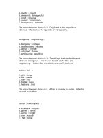
Table 12.1 Critical neighbor number for
different values of n. k
asym
is the CNN
for the G
k
graph and k
sym
is the same
number for the symmetric subgraph of G
k
.
Here, the CNN is defined as the minimum
value of k that guarantees that the gener-
ated topology is connected with probability
at least 0.95
nk
asym
k
sym
nk
asym
k
sym
10 6 6 100 9 9
20 8 8 250 9 9
25 8 8 500 9 9
50 8 9 750 9 10
75 9 9 1000 10 10
setting, the CNN is defined as the minimum value of k that guarantees that the generated
topology is connected with probability at least 0.95. Blough et al. considered both the G
k
graph and its symmetric subgraph G
−
k
. Note that the CNN in case of G
−
k
might be higher
than that of G
k
because the asymmetric link removal might disconnect the graph (see
Figures 12.1 and 12.2). The asymmetric CNN, k
asym
, and the symmetric CNN, k
sym
,for
different values of n are reported in Table 12.1.
As seen from the table, setting k = 9 provides connectivity w.h.p. for a wide range
of network sizes (from 50 to 500 nodes). Another important observation concerns the fact
that k
asym
and k
sym
have the same value, except for a few cases in which k
sym
= k
asym
+ 1.
This fact confirms that, as predicted by Corollaries 12.1.8 and 12.1.9, removing all the
asymmetric links has asymptotically negligible influence on network connectivity.
To gain more insights on neighbor-based connectivity, Blough et al. have also performed
a set of simulations in which the connectivity requirement on G
−
k
is weakened. In particular,
it is requested that at least 95% of the network nodes are in the same connected component
w.h.p. (here, w.h.p. means with probability at least 0.95). We call the minimum value of k
satisfying the above connectivity requirement wCNN, where w stands for weak.
The results of this experimental evaluation, which are reported in Table 12.2, are inter-
esting: contrary to the case of CNN, wCNN shows a converging behavior as n increases;
in particular, wCNN converges to 6 as n →∞.
It is interesting to compare the different values of the minimum number of neighbors
for connectivity that we have characterized in this section: depending on the connectivity
requirement on G
k
, this value can be equal to n − 1 (worst-case connectivity), or to O(log n)
(connectivity w.h.p.), or to 6 (most of the nodes in the largest connected component w.h.p.).
Note that in this latter case we do have a magic number of neighbors, which is 6.
Before ending this section, we give one more comment about the values of wCNN
and CNN reported in Table 12.2. These values indicate quite clearly (although there is
no theoretical support to this claim) that the giant component phenomenon, which we have
discussed in Section 4.1 in case of the CTR for connectivity, occurs in the k-neighbors graph
also. In the context of neighbor-based topology control, the giant component phenomenon
134 NEIGHBOR-BASED TOPOLOGY CONTROL
Table 12.2 WeakCNN and CNN for different
values of n. Here, wCNN is defined as the min-
imum value of k such that at least 95% of the
network nodes are in the same connected com-
ponent with probability at least 0.95
n wCNN CNN n wCNN CNN
10 6 6 100 7 9
20 7 8 250 7 9
25 7 8 500 6 9
50 7 9 750 6 10
75 7 9 1000 6 10
can be explained as follows. Assume every node in the network establishes a connection
to its closest neighbor, then to the second closest neighbor, and so on, until connectivity
is achieved. The experimental results reported in Table 12.2 indicate that a large connected
component in G
k
is formed quite soon in this closest-neighbor-connection process: w.h.p.,
most of the network nodes are in the same connected component after only six steps (i.e.
when k = 6), independent of n; on the other hand, if the goal is connecting all the nodes
in the network, then the connection process is very likely to stop after (log n) steps.
12.2 The KNeigh Protocol
The KNeigh protocol introduced in (Blough et al. 2003b) is a distributed implementation
of the computation of G
−
k
based on distance estimation. In other words, it is assumed that
when a node u receives a message from node v, u is able to estimate (possibly with a certain
error) the distance to node v. This can be accomplished by using one of the many distance
estimation techniques proposed in the literature. Among them, we cite the following:
– Radio signal strength indicator: Distance is estimated by comparing the transmitted
power at the sender (which is piggybacked in the message) with the received power at
the receiver of the message. This technique can be implemented without any additional
hardware on the nodes (RSSI registers are a standard feature in many wireless network
cards (Savvides et al. 2001)), but its accuracy is bonded to the accuracy of the radio
channel model used to predict path loss. Since path loss is very difficult to predict
in many environments (especially in presence of buildings, obstacles, and so on), it
turns out that RSSI-based distance estimation provides reasonable accuracy only in a
quite idealized setting (e.g. football field with all the nodes positioned at the ground
level) (Savvides et al. 2001);
– Time of arrival: Distance is estimated by comparing the time of arrival of different
types of signals. Typically, the radio signal is used in combination with acoustic, ultra-
sound, or infrared signals. Because of the use of different types of signals, ToA-based
techniques provide a much better accuracy than RSSI-based mechanisms, and can be
implemented at a reasonable hardware cost. For example, the technique proposed in
(Girod and Estrin 2001) uses a standard PC sound card to generate an acoustic signal,
NEIGHBOR-BASED TOPOLOGY CONTROL 135
which is received by a cheap microphone. The authors show that this technique pro-
vides good accuracy (below 3%) in realistic conditions. However, accuracy drops to
only 23% when the line of sight between the nodes is obstructed by heavy obstacles.
12.2.1 Protocol description
The KNeigh protocol, which is summarized in Figure 12.4, is very simple. Initially, every
node broadcasts its ID at maximum power (as usual, we assume that all the nodes have the
same maximum transmit power P
max
, and that the wireless medium is symmetric). Upon
receiving broadcast messages from other nodes, every node keeps track of its neighbors,
storing for each of them the estimated distance (this can be done by using one of the
techniques described above). After all the initial messages have been sent, every node in
the network knows its neighbor set and the distance-based ordering of the neighbors. Given
this information, every node computes its k-closest neighbors list KN, and broadcasts this
information at maximum power. By exchanging neighbor lists, nodes are able to determine
the set of symmetric neighbors
2
and to exclude the asymmetric neighbors from KN.Atthe
end of the protocol execution, KN(u) contains the list of neighbors of node u in the final
topology G
−
k
, and the (broadcast) transmit power of node u is set to the minimum value
needed to reach the farthest node in KN(u). Note that this value can be computed given the
received signal strength of the messages sent by the farthest node in KN(u).
Blough et al. proved the following properties of KNeigh (Blough et al. 2003b):
– Correctness: If all the nodes use the same maximum transmit power P
max
and the
wireless medium is symmetric, then algorithm KNeigh correctly computes the G
−
k
graph. To be precise, KNeigh computes a subgraph of G
−
k
, where every node is
connected to its k closest neighbors, or to the maximum possible number of neighbors
within the maximum transmitting range.
– Connectivity: Under the assumption that nodes are distributed uniformly at random in
a square of arbitrary side, and that P
max
is chosen in such a way that the maxpower
communication graph is connected w.h.p., and setting k to the CNN as indicated in
Corollary 12.1.9, the topology generated at the end of KNeigh execution is connected
w.h.p. For practical purposes, given the number n of network nodes, k can be set to
k
sym
as indicated in Table 12.1.
– Bounded physical node degree: The physical node degree of any network node at the
end of KNeigh’s execution is upper bounded by k.
– Termination: Under the assumption that the time interval between the instants at
which the first and the last node in the network broadcast the ID is at most ,for
some >0, and assuming a randomized scheduling to send messages, the protocol
terminates correctly after a certain finite time T , which depends on n and .
– Message complexity: Since every node in the network sends exactly two messages,
the total number of messages exchanged by KNeigh is 2n.
2
Two nodes are symmetric neighbors if and only if they appear in each other’s KN list.
136 NEIGHBOR-BASED TOPOLOGY CONTROL
Algorithm KNeigh:
(algorithm for node u)
k is the target number of neighbors (input parameter)
P
max
is the maximum node transmit power
N(u) is the neighbor set of node u
KN(u) is the k-closest neighbor set of node u
p(u) is the final (broadcast) transmit power of node u
1. Initialization
N(u) =∅
KN(u) =∅
2a. ID broadcast
send message (u, P
max
) at transmit power P
max
2b. Neighbors detection
upon receiving message (v, P
max
) from node v
N(u) = N(u) ∪{v}
estimate distance to v and store this information
3. Wait for stabilization time
4. Compute the k-closest neighbors list
order the nodes in N(u) according to the estimated distance
KN(u) = first k nodes in N(u) – (all the nodes if |N(u)|≤k)
5a. Neighbor list broadcast
send message (u, KN(u)) at transmit power P
max
5b. Neighbor lists reception
upon receiving message (v, KN(v)) from node v
store this information
6. Wait for stabilization time
7. Symmetric neighbor list computation
for each v ∈ KN(u) do
if u/∈ KN(v) then KN(u) = KN(u) −{v}
8. Transmit power computation
p(u) = minimum power level needed to reach the farthest node in KN(u)
Figure 12.4 The KNeigh protocol.