The Practice of System and Network Administration Second Edition phần 3 docx
Bạn đang xem bản rút gọn của tài liệu. Xem và tải ngay bản đầy đủ của tài liệu tại đây (7.14 MB, 105 trang )
6.1 The Basics 171
❖ Warning: Mobile Phones with Cameras Rented colocation facilities
often forbidcameras and therefore forbid mobile phones that include
cameras.
6.1.10 Console Access
Certain tasks can be done only from the console of a computer. Console
servers and KVM switches make it possible to remotely access a computer’s
console. For an in-depth discussion, refer to Section 4.1.8.
Console servers allow you to maintain console access to all the equip-
ment in the data center, without the overhead of attaching a keyboard,
video monitor, and mouse to every system. Having lots of monitors, or
heads, in the data center isaninefficient way to use the valuable resource
of data center floor space and the special power, air conditioning, and fire-
suppression syste
ms that are a part of it. Keyboards and monitors in data
centers also typically provide a very unergonomic environment to work in if
you spend a lot of time on the console of a server attached to a head in a data
center.
Console servers come in two primary flavors. In one, switch boxes allow
you to attach the keyboard, video monitor, and mouse ports of many machines
through the switch box to a single keyboard, video, and mouse (KVM). Try
to have as few such heads in the data center as you can, and try to make the
environment they are in an ergonomic one.
The other flavor is a console server for machines that support serial con-
soles. The serial port of each of these m
achines is connected to a serial device,
such as a terminal server. These terminal servers are on the network. Typi-
cally, some software on a central server controls them all (Fine and Romig
1990) and makes the consoles of the machines available by name, with au-
thentication and some level of access control. The advantage of this systemis
that an SA who is properly authenticated can access the console of a system
from anywhere: desk, home, and on the road and connected by remote access.
Installing a console server improves productivity and convenience, cleans up
the data center, and yields more space (Harris and Stansell 2000).
It can also be useful to have a few carts with dumb terminals or laptops
that can be used as portable serial consoles.
These carts can be conveniently
wheeled up to any machine and used as a serial console if the main console
server fails or an additional monitor and keyboard are needed. One such cart
is shown inFigure 6.15.
172 Chapter 6 Data Centers
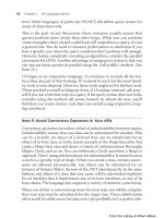
Figure 6.15 Synopsys has several serial console carts that can be wheeled up to a
machine if the main console server fails or if the one machine with a head in the
machine roomis in use.
6.1.11 Workbench
Another key feature for a data center is easy access to a workbench with plenty
of power sockets and an antistatic surface where SAs can work on machines:
adding memory, disks, or CPUs to new equipment before it goes into service
or perhaps taking care of something that has a hardware fault. Ideally, the
workbench should be near the data center but not part of it, so that it is not
6.1 The Basics 173
used as temporary rack space and so that it does not make the data center
messy. These work spaces generate a lot of dust, especially if new hardware
is unboxed there. Keeping this dust outside the data center is important.
Lacking space to perform this sort of work, SAs will end up doing repairs
on the data center floor and new installs at their desk, leading to unprofes-
sional, messy offices or cubicles with boxes and pieces of equipment lying
around. A professionally run SA group should look professional. This means
having a properly equipped and sufficiently large work area that is designated
for hardware work.
❖ People Should Not Work in the Data Center Time and time again,
we meet SAs whose offices are desks inside the data center, right next to
all the machines. We strongly recommend against this.
It is unhealthy for people to work long hours in the data center. The
data center has the perfect temperature and humidity for computers, not
people. It is unhealthy to work in such a cold room and dangerous to
work around so much noise.
It is also bad for the systems. People generate heat. Each person
in the data center requires an additional 600 BTU of cooling. That is
600 BTU of additional stress on the cooling system and the power to
run it.
It is bad financially. The cost per square meter of space is consider-
ably more expensive in a data center.
SAs need to work surrounded by reference manuals, ergonomic
desks, and so on: an environment that maximizes their productivity.
Remote access systems, once rare, are now inexpensive and easy to
procure.
People should enter the room only for work that can’t be done any
other way.
6.1.12 Tools and Supplies
Your data center should be kept fully stocked with all the various cables,
tools, and spares you need. This is easier to say than to do. With a large
group of SAs, it takes continuous tracking of the spares and supplies and
support from the SAs themselves to make sure that you don’t run out, or at
least run out only occasionally and not for too long. An SA who notices that
the data center is running low on something or is about to use a significant
174 Chapter 6 Data Centers
quantity of anything should inform the person responsible for tracking the
spares and supplies.
Ideally, tools should be kept in a cart with drawers, so that it can be
wheeled to wherever it is needed. In a large machine room, you should
have multiple carts. The cart should have screwdrivers of various sizes, a
couple of electric screwdrivers, Torx drivers, hex wrenches, chip pullers,
needle-nose pliers, wire cutters, knives, static straps, a label maker or two,
and anything else that you find yourself needing, even occasionally, to work
on equipment in the data center.
Spares and supplies must be well organized so that they can be quickly
picked up when needed and so that it
is easy to do an inventory. Some people
hang cables from wall hooks with labels above them; others use labeled bins
of varying sizes that can be attached to the walls in rows. A couple of these
arrangements are shown inFigures 6.16 and 6.17. The bins provide a more
compact arrangement but need to be planned for in advance of laying out
the racks in the data center, because they will protrude significantly into the
aisle. Small items, such as rack screws and terminators, should be inbins or
small drawers. Many sites prefer to keep spares inadifferent room with easy
access from
the data center. A workroom near the data center is ideal. Keeping
spares in another roommay also protect them from the event that killed
Figure 6.16 Various sizes of labeled blue bins are used to store a variety of data center
supplies at GNAC, Inc.
6.1 The Basics 175
Figure 6.17 Eircom uses a mixture of blue bins and hanging cables.
the original. Large spares, such as spare machines, should always be kept in
another room so that they don’t use valuable data center floor space. Valuable
spares, such as memory and CPUs, are usually kept in a locked cabinet.
If possible, you should keep spares for the components that you use or
that fail most often. Your spares inventory might include standard disk drives
of various sizes, power supplies, memory, CPUs, fans, or even entire machines
if you have arrays of small, dedicated machines for particular functions.
It is useful to have many kinds of carts and trucks: two-wheel hand-trucks
for moving crates, four-wheel flat carts for movi
ng mixed equipment, carts
with two or more shelves for tools, and so on. Mini-forklifts with a hand-
cranked winch are excellent for putting heavy equipment into racks, enabling
you to lift and position the piece of equipment at the preferred height in the
rack. After the wheels are locked, the lift is stable, and the equipment can be
mounted in the rack safely and easily.
6.1.13 Parking Spaces
Asimple, cheap, effective way to improve the life of people who work in the
data center is to have designated parking spaces for mobile items. Tools that
are stored in a cart should have their designated place on the cart labeled.
Carts should have labeled floor space where they are to be kept when unused.
When someone is done using the floor tile puller, there should be a labeled
176 Chapter 6 Data Centers
spot to return the device. The chargers for battery-operated tools should have
a secure area. In all cases, the mobile items should be labeled with their return
location.
Case Study: Parking Space for Tile Pullers
Two tile pullers were in the original Synopsys data center that had a raised floor. How-
ever, because there was no designated place to leave the tile pullers, the SAs simply
put them somewhere out of the way so that no one tripped over them. Whenever
SAs wanted a tile puller, they had to walk up and down the rows until they found
one. One day, a couple of SAs got together and decided to designate a parking space
for them. They picked a particular tile where no one would be in danger of tripping
over them, labeled the tile to say, ‘‘The tile pullers live here. Return them after use,’’
and labeled each tile puller with, ‘‘Return to tile at E5,’’ using the existing row and
column labeling on the walls of the data center. The new practice was not particularly
communicated to the group, but as soon as they saw the labels, the SAs immediately
started following the practice: It made sense, and they wouldn’t have to search the
data center for tile pullers any more.
6.2 The Icing
You can improve your data center above and beyond the facilities that we
described earlier. Equipping a data center properly is expensive, and the im-
provements that we outline here can add substantially to your costs. But if
you are able to, or your business needs require it, you can improve your data
center by having much wider aisles than necessary and by having greater
redundancy in your power and HVAC systems.
6.2.1 Greater Redundancy
If your business needs require very high availability, you will need to plan
for redundancy in your power and HVAC systems, among other things. For
this sort of design, you need to understand circuitdiagrams and building
blueprints and consult with the people who are designing the system to make
sure that you catch every little detail, because it is the little detail you miss
that isgoing to get you.
For the HVAC system, you may want to have two independent parallel
systems that run all the time. If one fails, the other will take over. Either one
on i
ts own should have the capacity to cool the room. Your local HVAC
engineer should be able to advise you of any other available alternatives.
6.2 The Icing 177
For the power system, you need to consider many things. At a relatively
simple level, consider what happens if a UPS, a generator, or the ATS fails.
You can have additional UPSs and generators, but what if two fail? What if
one of the UPSs catches fire? If all of them are in the same room, they will all
need to be shut down. Likewise, the generators should be distributed. Think
about bypass switches for removing from the circuit, pieces of equipment
that have failed, in addition to the bypass switch that, ideally, you already
have for the UPS. Those sw
itches should not be right next to the piece of
equipment that you want to bypass, so that you can still get to themif the
equipment isonfire. Do all the electrical cables follow the same path or meet
at somepoint? Could that be a problem?
Within the data center, you may want to make power available from sev-
eral sources. You may want both alternating current (AC) and direct current
(DC) and power, but you may also want two different sources of AC power
for equipment that can have two power supplies or to power each half of a
redundant pairofmachines. Equipment with multiple power supplies should
take power from different power sources (see Fi
gure 6.18).
❖ High-Reliability Data Centers The telecommunications industry has
an excellent understanding about how to build a data center for reli-
ability, because the phone systemis used for emergency services and
must be reliable. The standards were also set forth when telecommu-
nication monopolies had the money to go the extra distance to en-
sure that things were done right. Network Equipment Building System
(NEBS) is the U.S. standard for equipment that may be put in a phone
company’s central office. In Europe, the equipm
ent must follow the
European Telecommunication Standards Institute (ETSI) standard. NEBS
and ETSI set physical requirements and testing standards for equipment,
as well as minimums for the physical roomitself. These document in
detail topics such as space planning, floor and heat loading, tempera-
ture and humidity, earthquake and vibration, fire resistance, transporta-
tion and installation, airborne contamination, acousticnoise, electrical
safety, electromagnetic interference, electrostaticdischarge (ESD) im-
m
unity, lightning protection, DC potential difference, and bonding and
grounding. We only mention this to show how anal retentive the telecom
industry is. On the other hand, when was the last time you picked up
your telephone and didn’t receiveadial tone in less than a second? The
178 Chapter 6 Data Centers
Figure 6.18 GNAC, Inc.,brings three legs of UPS power intoasingle power strip.
Redundant power supplies inasingle piece of equipment are plugged into different
legs to avoidsimultaneous loss of power to both power supplies if one leg fails.
NEBS and ETSI standards are good starting places when creating your
own set of requirements for a very-high-availability data center.
For a high-availability data center, you also need good process. The
SAS-70 standard applies to service organizations and is particularly rel-
evant to companies providing services over the Internet. SAS-70 stands
for Statement of Auditing Standards No. 70, which is entitled “Reports
on the Processing of Transactions by Service Organizations.” It isanau-
diting standard established by the American Institute of Cert
ified Public
Accountants (AICPA).
6.3 Ideal Data Centers 179
6.2.2 More Space
If space is not at a premium, it isnice to have more aisle space than you
need in your computer room to meet safety laws and to enable you to move
equipment around. One data center that Christine visited had enough aisle
space to pull a large piece of equipment out of a rack onto the floor and
wheel another one behind itwithout knocking into anything. Cray’s data
center in Eagan, Minnesota, had aisles that were three times the depth of the
deepest machine. If you are able to allocate this much space, based on your
long-term plans—so that you will not have to move the racks later—treat
yourself. It is a useful luxury, and
it makes the data center a much more
pleasant environment.
6.3Ideal Data Centers
Different people like different features in a data center. To provide some food
for thought, Tom and Christine have described the features each would like
inamachine room.
6.3.1Tom’s Dream Data Center
When you enter my dream data center, the first thing you notice is the voice-
activated door. To make sure that someone didn’t record your voice and play
it back, you are prompted for a dictionary word, which you must then repeat
back. The sliding door opens. It iswide enough to fit a very large server, such
as an SGI Challenge XL, even though those servers aren’t sold any more.
Even though the room has a raised floor, it is the sameheight as the hallway,
which means that no ramp is required.
The roomis on the fourth floor of a six-story building. The UPS units
and HVAC systems are in the sixth-floor attic, with plenty of room to grow
and plenty of conduit space if additional power or ventilation needs to be
brought to the room. Flooding is unlikely.
The racks are all the same color and from the same vendor, which makes
them look very nice. In fact, they were bought at the sametime, so the
paint fades evenly. A pull-out drawer at the halfway point of every third
rack has a pad of paper and a couple of pens. (I never can have too many
pens.) Most of the servers mount directly in the rack, but a few have five
shelves: two below the drawer, one just above the drawer, and two farther
up the rack. The shelves are at the sameheight on all racks so that it looks
neat and are strong enough to hold equipm
ent and still roll out. Machines
180 Chapter 6 Data Centers
can be rolled out to do maintenance on them, and the cables have enough
slack to permitthis. When equipment istobemounted, the shelves are re-
moved or installed on racks that are missing shelves. Only now do you notice
that some of the racks—the ones at the far end of the room—are missing
shelves in anticipation of equipment that will be mounted and not require
shelves.
The racks are 19-inch, four-post racks. The network patch-panel racks,
which do not require cooling, have doors on the front and open in the back.
The racks are locked together so that each row is self-stable.
Each rack isaswide as a floor-tile: 2 feet, or one rack per floor tile. Each
rack is 3 feet deep, or 1.5 floor t
iles deep. A row of racks takes up 1.5tiles,
and the walkway between them takes an equal amount of space. Thus, every
three tiles isacomplete rack and walkway combination that includes one tile
that iscompletely uncovered and can therefore be removed when access is
required. If we are really lucky, some or all rows have an extra tile between
them. Having the extra 2 feet makes it much easier to rack-mount bulky
equipment (see Figure 6.19).
The racks are in rows that are no more than 12 racks long. Between
every row is a walkway large enough to bring the largest piece of equipment
through. Some rows are missi
ng or simply missing a rack or two nearest the
walkway. This space is reserved for machines that comewith their own rack
or are floor-standing servers.
If the roomis large, it has multiple walkways. If the roomissmall, its
one walkway is in the middle of the room, where the door is. Another door,
used less frequently, is in the back for fire safety reasons. The main door
gives an excellent view of the machine room when tours come through. The
machine room has a large shatterproof plasticwindow. Inside the room
,by
the window, is a desk with three monitors that display the status of the LAN,
WAN, and services.
The back of each rack has 24 network jacks cable certified for Cat-6
cable. The first 12 jacks go to a patch panel near the network equipment.
The next 12 go to a different patch panel near the console consolidator.
Although the consoles do not require Cat-6 copper, using the same copper
consistently means that one can overflow network connections into the con-
sole space. If perhaps fiber may someday be needed, every rack—or simply
every other rack—has sixpairs of fiber that run back to a fiber patch panel.
The popularity of storage-area networks (SANs) is making fiber popular
again.
6.3 Ideal Data Centers 181
Door
Wall
2 ft.
square
Back of racks
Back of racks
Front of racks
Front of racks
Walkway
Figure 6.19 Simple floor plan that provides open space
The last row of racks is dedicated for network equipment. The patch
panels have so much wire coming into them that they can never be moved,
so this row is in the far back corner. Also, inthis part of the roomis a table
with three monitors and keyboards. Two are for the KVM switch; the third
connects to the serial console concentrator directly. One rack is dedicated
to connections that go out of the room. Near it is a row of fiber-to-copper
adapters. Vendors now make a single unit that supplies power to many such
adapters that slide into it, thus eliminating the rat’
s nest of power cables and
power bricks.
182 Chapter 6 Data Centers
The network equipment rack also has a couple of non-UPS outlets. They
are colored differently and are well labeled. Sometimes, the UPS will be down,
but the network must be up, and the redundant power supplies can be plugged
into these non-UPS outlets.
Air conditioning is fed under the floor. Every other floor tile in the
walkways has pin holes to let air out. The tiles under each rack have large
holes to let air in, so air can flow up the back of each piece of equip-
ment. The system forces the airwith enough pressure to properly cool every
rack. The cold air flows up the front of the rack, and each machine’s fans
pull the air toward the back of the rack. Rows of racks alternate which is
front and which is back. That i
s, if you walk down an aisle, you’ll see ei-
ther all fronts or all backs. The aisle with all fronts isa“cold row” and
receives the cold air from holes in the floor. The aisle with all backs is
a “hot row” and receives the hot aircoming from the backs of the ma-
chines, which is then exhausted up and out the room through vents in the
ceiling.
Along the left and right sides of the back of each rack is a PDU with
widely spaced outlets. Each pair of racks isonadifferent circuit that comes
from the UPS.
Each circuit is marked with a circuitnumber so that redundant
services can be placed on different circuits.
Every cable is labeled on each end withaunique number, and every host
is labeled with name, IP address, and MAC address. The two label printers in
the room are labeled with the room number of the data center and a warning
that stealing the device will lead to certain death.
Also under the floor are cable trays, with separate ones for power and
for networking. Because power and networking are prewired, there should
be little need to ever open the floor.
Outside the machine room through the other door is a work area. It is
separated fro
m the main room to keep out the dust. This room has wide wire
shelves that hold new machines being installed. There are workbenches with
power sockets and an antistatic surface where repairs can be done without
doing more damage to the equipment. Also inthis roomis a set of drawers
filled with tools, spare parts, and bins of cables of various lengths and types.
There are 20 extra pairs of wire cutters, 40 extra Phillips screwdrivers, and 30
extra flathead screwdrivers. (At the rate they are stolen, that supply should
last a year.)
This ends our tour of Tom’s dream data center. As you leave, the tour
guide hands you a com
plimentary Linux box.
6.3 Ideal Data Centers 183
❖ The Floor Puller Game Here’s a great game to play inawide open
space in a room witharaised floor, such as the open area behind the
desk at a helpdesk. Thisgame should be played when your boss isn’t
around. You will need two people and one floor puller.
Each person sits or stands at a different end of the room. One player
throws the floor puller at a tile. If itsticks, the player removes the
tile and accumulates it inapile inhis or her end of the room. The
two players alternate, taking turns until all the floor tiles are missing.
You must walk on the grid and not touch the floor below the tiles.
If you fall into the floor, you must return a floor t
ile to one place.
When all the tiles are removed, whoever has the larger pile of floor tiles
wins.
If you play this enough, the edges of the tiles will be damaged ina
year, and you will need to purchase a new floor. We don’t recommend
that you play thisgame, but if you are in the business of installing and
repairing raised floors, teaching it to your customers might increase your
sales. (You didn’t hear that from us!)
6.3.2 Christine’s Dream Data Center
Christine’s dream data center has double doors that are opened with a hands-
free security system, such as proximity badges or voice activation, so that it is
easy for people carrying equipment to get access. The double doors are wide
enough to get even the largest piece of equipment through and is on the same
level as, and is convenient to, the receiving area, with wide corridors between
the two.
The data center has backup power from a generator with enough capacity
to hold the machines and lighting in the data center, the HVAC system, the
UPS charging, the phone switches, the SA work area, and the customer service
center. The security-access syste
mis also on the protected power system.
The generator has large tanks that can be refueled while it is running. The
generator is tested once a week.
An ATS is tunable for what is considered to be acceptable power.
4
A UPS
protects the data center and has enough power to run for 30 minutes, which
4. Christine once saw an ATS that found utility power acceptable when the UPS didn’t, so the UPS
ran off batteries, and the generator didn’t get switched on—what a nightmare.
184 Chapter 6 Data Centers
should be enough to manually switch to a backup generator, provided that
the backup generator is there already.
The data center does not have a raised floor. The air ispumped in from
overhead units. The room hasahigh ceiling with no tiles. The roomispainted
matte black from a foot above the racks, with drop-down lights that are
at the level where the black paint starts. This makes the overhead HVAC
inconspicuous.
An overhead power bus supports two power sources—different UPS,
ATS, generator, and power distribution panels and power bus for each, with
different physical locations for each set of equipment, but that couldn’tbe
justified for the average s
ite data center.
The data center is prewired with one 36-port, 2U patch panel at the
top of each rack, brought back to racks in the network row. In the network
row, patch-panel racks are interspersed between racks that hold the network
equipment. There is lots of wire management.
The data center has 7-foot-tall, four-post racks (black), with 19-inch-
wide rack-mount spaces that are 36 inches deep with no backs, fronts, or
sides. They have threaded mounting holes, and the sides of the shelves mount
onto vertical rails, which can be moved just about anywhere. The shelves are
not as deep as the racks—just 30 inches—to leave room for cables that are
plugged into the machines and PDUs and vertical wire management within
the racks
. Extra vertical rails can be moved for rack mounting different-depth
equipment. The racks have vertical PDUs with lots of outlets down one side.
If different power sources are in the machine room, the racks have power
available from both. Lots of 1- and 2-foot power cables are available, so no
power cords dangle. Vertical wire management goes down the other side and
horizontally on an as-needed basis. Several short stepladders are available so
that vertically challenged SAs can reach the top.
The data center has network patch cables from 3 feet to 10 feet at every
1-foot interval, plus a few that are 15, 20, 25, 30, 35, 40, 45, and 50 feet
long. All network cables are prelabeled with unique serial numbers that also
encode length and type. There are blue bins for storing all the various ki
nds
of cables and connectors in the data center where it is convenient.
The machines are labeled front and back with the DNS name. Network
interfaces are labeled with the network nameornumber.
A couple of carts with drawers have all the tools you could possibly need.
There are battery-powered screwdrivers, as well as manual ones. Each cart
has a label maker. A work area off the machine room hasanice wide bench,
6.4 Conclusion 185
lots of power, and static protection. Sets of tools are kept to hand in there
also.
6.4 Conclusion
A data center takes a lot of planning to get right, but whatever you build,
you will be stuck with it for a long time, so it is worth doing right. A badly
designed, underpowered, or undercooled data center can be a source of reli-
ability problems; a well-designed data center should see you safely through
many problems.
Power, air conditioning, and fire-suppression systems are relatively im-
mutable key components of the data center. They can also have the greatest
effects if they go wrong. Messy wiring issomething that everyone has experi-
enced and would rather not have to deal with. With good advance planning,
you can reduce your night
mares in that area.
Access to the room for getting equipment in and moving it around is an-
other key area that you need to plan in advance. And along with access comes
security. The data center is a business-critical room that holds a lot of valuable
equipment. The security-access policies must reflect that, but the mechanism
selected should be convenient for people with armloads of equipment to use.
Building a good, reliable data center is costly but has significant payback.
However, you can do simple, inexpens
ive things to make the data center a
nicer and more efficient environment to work in. Everyone appreciates having
a convenient place to work on broken equipment with all the tools, spares,
and supplies that you need on hand, and, relatively speaking, the cost for
that is very low. Labeling all equipment well and having designated parking
spaces for mobile resources will provide you with inexpensive time-saving
benefits. Seek ideas from the SAs; all of them will have features that they
particularly like or disl
ike. Incorporate the good ones, and learn from the
negative experiences of others.
For companies with lots of space, it isnice to make the data center more
spacious than it needs to be. And for those with lots of money and very high
reliability requirements, you can do much with the key systems of power and
air conditioning to add greater redundancy that will make the room even
more reliable.
To get the most out of a data center, you need to design it well from the
start. If you know that you are going to be building a new one, it is worth
spending a lot of time up front to get itright.
186 Chapter 6 Data Centers
Exercises
1. What natural disasters might occur in your area? What precautions have
you taken for natural disasters, and what improvements could you make?
2. What problems have you found with your racks? What would you like
to change?
3. Could you make use of prewiring in your current data center, if you had
it? If not, what would you have to do to make it useful? How much do you
think prewiring would help in cleaning up the wiring in your data center?
4. What is the power capacity of your data center? How close are you to
reaching it?
5. If you have separate power circuits fro
m different UPSs in your data
center, how well are they balanced? What could you do to balance them
better?
6. How much space is occupied with monitors in your data center? How
many could you pull out with the use of serial console servers? How
many could you pull out by deploying KVM switch boxes?
7. Where do you work on broken machines? Is there an area that could be
turned into a workbench area?
8. What tools would you want in a cart in the data center?
9. What supplies do you think you would want in the data center, and how
many of each? What should the high and low supply levels be for each
item?
10. What spares would you want, and how many of each?
11. What equipment do you have that is always “
walking off”? Can you
think of good parking spaces for it?
Chapter 7
Networks
A site’s network is the foundation of its infrastructure. A poorly built network
affects everyone’s perception of all other components of the system. A net-
work cannot be considered in isolation. Decisions made as part of the network
design and implementation process influence how infrastructure services are
implemented. Therefore, the people who are responsible for designing those
services should be consulted as part of the network design process.
We cannot explain every detail of network design and implementation in
this short chapter. Entire shelves of books are devoted to the topic. However,
we can relate the points we have found to be the most important. An excellent
starting point is Perlman (1999). For Transmission Control Protocol/Internet
Protocol (TCP/IP), we recommend Stevens (1994) and Comer (2000). To un-
derstand how routers and switches work, see Berkowitz (1999). Berkowitz
(1998) also has written a book on network addressing architectures. For
more information on specific technologies, see Black (1999). For WANs, see
Marcus (1999) and Feit (1999). For routing protocols, see Black (2000).
Other books concentrate on a single protocol or technology, such as Open
Shortest Path First (OSPF) [Moy 2000, Thomas 1998a]; Enhanced Inte-
rior Gateway Routing Protocol (EIGRP) [Pepelnjak 2000]; Border Gate-
way Protocol (BGP) [Stewart 1999, Halabi and McPherson 2000]; Mail
Protocol Label Switching (MPLS), VPNs, and QoS [Black 2001, Guichard
and Pepelnjak 2000, Lee 1999, Vegesna 2001, Keagy 2000, and Maggiora
et al. 2000]; multicast [Williamson 2000]; Asynchronous Transfer Mode
(ATM) [Pildush 2000]; and Ethernet [Spurgeon 2000].
Networking is an area of rapid technological development, and therefore
the approaches and implementation possibilities change significantly over the
years. In this chapter, we identify areas that change over time, as well as some
of the constants in the networking realm.
187
188 Chapter 7 Networks
This chapter is primarily about an e-commerce organization’s internal
LANs and WANs, but we also look at a campus environment.
7.1 The Basics
When building a network, your basic goal is to provide a reliable, well-
documented, easy-to-maintain network that has plenty of capacity and room
for growth. Sounds simple, doesn’t it?
Many pieces at different layers combine to help you reach—or fail to
reach—that goal. This section discusses those building blocks, covering
physical-network issues, logical-network topologies, documentation, host
routing, routing protocols, monitoring, and administrative domains. This
section also discusses how components of the network design interact with
one another and with the design of the services that run on top of the
network.
WAN and LAN designs differ significantly. Over time, cyclic trends make
them more similar, less similar, then more similar again. For example, at one
time, it was popular for LAN topologies to be dual-connected rings of Fiber-
Distributed Data Interface (FDDI) connections to provide fault tolerance.
This lost popularity as Fast (100MB) Ethernet arose, which was a bus ar-
chitecture. Meanwhile, WANs were adopting ring architectures, such as syn-
chronous optical network (SONET) and multiwavelength optical network
(MONET). In early 2007, draft proposals for 10GB Ethernet LAN technol-
ogy return to ring architectures. We have come full circle.
7.1.1 The OSI Model
The Open Systems Interconnection (OSI) reference model for networks has
gained widespread acceptance and is used throughout this chapter. The model
looks at the network as logical layers and is briefly described in Table 7.1.
Network devices decide the path that data travels along the physical net-
work, which consists of cables, wireless links, and network devices (layer 1).
A network device that makes those decisions based on hardware or MAC
address of the source or destination host is referred to as a layer 2 device.A
device that makes decisions based on the IP (or AppleTalk or DECnet) ad-
dress of the source or destination host is known as a layer 3 device. One that
uses transport information, such as TCP port numbers, is a layer 4 device.
Engineers more familiar with TCP/IP networking often simplify this as
follows: layer 1, the physical cable; layer 2, devices that deal with a particular
7.1 The Basics 189
Table 7.1 The OSI Model
Layer Name Description
1 Physical The physical connection between devices: copper, fiber, radio, laser
2 Data link Interface (or MAC) addressing, flow control, low-level error
notification
3 Network Logical addressing (e.g., IP addresses) and routing (e.g., RIP, OSPF,
IGRP)
4 Transport Data transport, error checking and recovery, virtual circuits (e.g.,
TCP sessions)
5 Session Communication-session management (e.g., AppleTalk name
binding, or PPTP)
6 Presentation Data formats (e.g., ASCII, Unicode, HTML, MP3, MPEG),
character encoding, compression, encryption
7 Application Application protocols, e.g., SMTP (email), HTTP (web), and FTP
(file transfer)
LAN; layer 3, the routers and gateways that route packets between LANs;
layer 4, the protocol being used.
Layer 5 is a layer that doesn’t map well into the world of TCP/IP. Layer 6 is
the data format: ASCII, HTML, MP3, or MPEG. Encryption and compression
are usually handled here also.
Layer 7 is the application protocol itself: HyperText Transfer Protocol
(HTTP) for web serving, SMTP for email transmission, IMAP4 for email
access, File Transfer Protocol (FTP) for file transfer, and so on.
The OSI model is a useful guideline for understanding the way networks
are intended to work, but many layering violations occur in the real world.
For example, a VPN connection made through an HTTPS proxy is sending
layers 3 and 4 traffic over a layer 7 application protocol.
❖ Layers 8, 9, and 10 A common joke is that the OSI model has three
additional layers:
•
Layer 8: User
•
Layer 9: Financial
•
Layer 10: Political
Many corporate network architectures focus on solving problems at
layer 10 but are limited by layer 9 in what they can achieve.
190 Chapter 7 Networks
7.1.2 Clean Architecture
A network architecture should be as clean and simple to understand as it can
be. It should be possible to briefly describe the approach used in designing the
network and draw a few simple pictures to illustrate that design. A clean ar-
chitecture makes debugging network problems much easier. You can quickly
tell what path traffic should take from point A to point B. You can tell which
links affect which networks. Having a clear understanding of the traffic flow
on your network puts you in control of it. Not understanding the network
puts you at the mercy of its vagaries.
A clean architecture encompasses both physical- and logical-network
topologies and the network protocols that are used on both hosts and network
equipment. A clean architecture also has a clearly defined growth strategy for
both adding LAN segments and connecting new remote offices. A clean net-
work architecture is a core component behind everything discussed later in
this chapter.
Case Study: Complexity and Vendor Support
A network architecture that can’t be explained easily makes it difficult to get support
from vendors when you have a problem. A network administrator discovered that
the hard way. When an outage in an overly complicated network occurred, anyone
he talked to, either locally or at a vendor, spent a lot of time trying to understand
the configuration, let alone come up with suggestions to fix the problem. Calling
vendor support lines wasn’t very useful, because the front-line support people could
not understand the network being debugged; sometimes, the vendor simply had
difficulty believing that anyone would use such a complicated design! After being
escalated to higher levels of customer support, he was told that the products weren’t
supported in such odd configurations and was urged to simplify the design rather
than push so many different vendors’ products to their limits.
Case Study: Complexity and Support by Network Administrators
When debugging a complicated network, the network administrator at one site found
herself spending more time figuring out what network paths existed than debugging
the problem. Once the network architecture was simplified, problems were debugged
in less time.
7.1 The Basics 191
We recommend limiting the number of network protocols on a given
WAN. Most networks have done this in recent years, migrating all data net-
works to TCP/IP rather than trying to mix it with Novell IPX, AppleTalk,
and other protocols. If needed, those protocols can be tunneled over TCP/IP,
using various encapsulation protocols. This approach is also less expensive
than having a different WAN for each protocol.
7.1.3 Network Topologies
Network topologies change as technologies and cost structures change, as
well as when companies grow, set up large remote offices, or buy other com-
panies. We introduce some of the common topologies here.
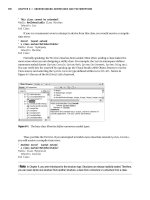
One topology often seen in wide-area, campus-area, and local-area net-
works is a star, whereby one site, building, or piece of network hardware is
at the center of the star, and all other sites, buildings, or networks are con-
nected to the center. For example, a single building or a campus might have
one layer 2 or layer 3 device to which all hosts or all networks are connected.
That device is the center of a star. A LAN with a star topology is illustrated
in Figure 7.1. For a WAN, if all wide-area connectivity is brought into one
building, that building is the center of the star, as illustrated in Figure 7.2.
A star topology has an obvious single-point-of-failure problem: A failure at
the center of the star disrupts all connectivity between the points of the star.
In other words, if all hosts in a building are connected to a single switch,
Switch
Switch
Switch
Switch
Switch
Switch
Switch
Router
Figure 7.1 A local-area or campus-area network with a star topology
192 Chapter 7 Networks
Field
office
Field
office
Field
office
Field
office
Field
office
Router
Router
Router
Router
Router
Main
office
Figure 7.2 A wide-area network with a star topology
all connectivity is lost. If all wide-area sites are connected through one build-
ing that loses power, they cannot communicate with one another or with the
site they connect through, but communication within each individual wide-
area site still works. However, a star topology is easy to understand, simple,
and often cost-effective to implement. It may be the appropriate architecture
to use, particularly for relatively small organizations. One simple improve-
ment on this design is to have each link be redundant between the two end
points and have a spare for the center point.
A common variant of the star topology consists of multiple stars, the
centers of which are interconnected with redundant high-speed links
(Figure 7.3). This approach limits the effects of a failure of a single star-
center point. Companies with geographically disparate offices often use this
approach to concentrate all long-distance traffic from a single geographic
area onto one or two expensive long-haul lines. Such a company also typ-
ically provides lots of application-layer services at each star-center site to
reduce long-haul traffic and dependence on the long-distance links.
Ring topologies also are common and are most often used for particular
low-level topologies, such as SONET rings. Ring topologies are also found in
LANs and campus-area networks and are sometimes useful for WANs. In a
ring topology, each network entity—piece of network hardware, building, or
site—is connected to two others so that the network connectivity forms a ring,
7.1 The Basics 193
Multiple
links
Multiple
links
German
office
French
office
United
Kingdom
office
Bulgarian
office
Austin
office
New
Jersey
office
Denver
office
Office in
Singapore
Office in
Japan
Office in
Malaysia
Main
European
office
Main
U.S.
office
Main
Asian
office
Figure 7.3 A multiple-star topology for a WAN, based on geographic hubs
as shown in Figure 7.4. Any one link or network entity can fail without affect-
ing connectivity between functioning members of the ring. Adding members
to the ring, particularly in a WAN, can involve reconfiguring connectivity at
multiple sites, however.
Another architecture that sites concerned about redundancy and avail-
ability use looks like a multistar topology, but each leaf node
1
has a backup
connection to a second star center, as shown in Figure 7.5. If any star-center
node fails, its leaf nodes revert to using their backup connections until the
primary service has been restored. This hybrid model permits an organization
to manage cost/reliability trade-offs for each site.
1. A leaf node is a network entity that handles only traffic originating at or destined for local machines
and does not act as a conduit for other traffic. In a simple star topology, every node except the center node
is a leaf node.
194 Chapter 7 Networks
Router
/
office/
switch
Figure 7.4 A ring topology, with each network device connected to two others
French
office
Texas
office
Florida
office
Singapore
office
Japan
office
Colorado
office
New
Jersey
office
UK
office
Main
European
office
Secondary
European
office
Main U.S.
office
Secondary
U.S. office
Main
Asian
office
Secondary
Asian
office
Figure 7.5 A redundant multiple-star topology for a WAN. The core is a ring, for
reliability. Small sites connect in star topology for cost and simplicity.
7.1 The Basics 195
Many other network topologies are possible, including the chaos topol-
ogy, which largely describes the topology of the Internet. A chaotic topology
ensues when each node can pick any one or more willing upstream nodes
to use as a path to the rest of the networks. However, you cannot expect
anyone to accurately describe or draw a connectivity map for a chaotic net-
work without the aid of complicated mapping software. Attempts to pro-
duce maps of the Internet have generated interesting and useful pictures
(Cheswick’s 1998).
An architecture that cannot be drawn or described without aids is not
clean. The Internet survives, however, because it is highly adaptive and fault
tolerant: The rest does not stop working because of an outage elsewhere. In
fact, outages occur all over the Internet all the time, but because they are small
and affect only specific, usually downstream, sites, they go unnoticed by the
greater network. That is not true in a corporate or university network, where
each part is often heavily dependent on other parts. The chaos approach is not
a reliable model to use in a network where availability of every component
matters.
What is normally drawn as the network map is the logical network
topology. It generally shows only network devices, such as routers, that oper-
ate at layer 3 and above, and represents each subnetwork that is handled by
one or more layer 2 devices, such as switches, as a single entity. The logical-
network topology that makes the most sense for any given site varies with
technologies and cost structures. Differing logical-network maps of a single
network may sometimes be drawn depending on what specific features need
to be highlighted for the audience.
A simple rule of thumb about limiting network complexity is that a site’s
network architects and senior network administrators should all be able to
sketch, without aids, the key features and basic structure of the network
topology. If other sources of information are needed, the architecture is not
clean and easy to understand.
The logical-network topology cannot be designed in isolation. It influ-
ences, and is influenced by, other aspects of the computing infrastructure. In
particular, the logical-network design, its physical implementation, and the
routing topologies that will be used across that network are all interdepen-
dent. In addition, the architecture of network services, such as email, Internet
access, printing, and directory services, must influence and be influenced by
the network architecture.