mcgraw hill wireless data demystified phần 2 pptx
Bạn đang xem bản rút gọn của tài liệu. Xem và tải ngay bản đầy đủ của tài liệu tại đây (578.68 KB, 59 trang )
Wireless Data
Network Protocols
2
CHAPTER
2
Copyright 2003 by The McGraw-Hill Companies, Inc. Click Here for Terms of Use.
38
Part 1: Overview of Wireless High-Speed Data Technology
Popular wireless data networking protocols such as Bluetooth, IEEE
802.11, and HomeRF were originally developed for the 2.4-GHz frequency
band by organizations that made design tradeoffs based on values such
as complexity, price, and performance. Because the protocols were devel-
oped independently and these values differed according to the markets
and applications the organizations intended to serve, the various proto-
cols do not easily interoperate with one another and can cause signifi-
cant mutual interference when functioning in the same radio space. The
problem becomes especially acute in environments such as residential
networks where a single network may be required to serve a broad range
of application classes.
A newer high-performance wireless data LAN standard, IEEE 802.11a,
operates in the 5-GHz band and offers much higher speeds than previous
WLAN standards, but does not adequately provide for unified networks
that support multiple classes of devices with differing speed, performance,
power, complexity, and cost requirements. These differing classes of
devices will become increasingly important as LANs move beyond the lim-
its of office-oriented computer interconnection services and into the realm
of data, video, and audio distribution services for interconnected devices
in offices and homes. (The Glossary defines many technical terms, abbre-
viations, and acronyms used in the book.)
Nevertheless, the data wireless marketplace is booming. New wireless
data products are being introduced daily. The unlicensed industrial/
scientific/medical (ISM) band at the 900-MHz and 2.4-GHz frequencies
creates opportunities for high-quality wireless data products to be intro-
duced. Wireless home networking initiatives are being announced and
developed, including the BlueTooth, HomeRF, and IEEE 802.11 working
groups and others. Industry leaders seek technologies for new digital
cordless telephones with high-end features. There is a high level of
expertise required to design high-speed and high-quality wireless data
products in these spread-spectrum product market segments. Large con-
sumer product manufacturers are turning to technology providers to
obtain the latest wireless data technologies and shorten time to market.
The system-on-a-chip (SoC) marketplace is “exploding” too. Application-
specific integrated circuit (ASIC) complexity is estimated to reach
7.2 million gates by the end of 2003. This allows multiple functionality to
be integrated into a single chip, lowering the cost and size of products
based on such chips.
Because a single company becomes unable to design such high-
integration components, and with demanding time-to-market constraints,
system companies are turning to third-party ASIC designers. These
third parties provide intellectual property (IP) in the form of subsystem
ASIC designs as “building blocks” to their complete SoC designs. Compa-
nies like ARM, MIPS, RAMBUS, and others have already seized that
Chapter 2: Wireless Data Network Protocols
opportunity and offer differentiated IP cores. The third-party IP market
is estimated to grow from $5.9 billion in 2003 at a compound annual
growth rate of 76 percent. There is a very special opportunity for compa-
nies than can offer special experience and intellectual property in the
spread-spectrum area to companies that wish to integrate wireless data
connectivity in their system-on-a-chip products in the form of wireless
data IP cores. The marketplace for wireless data products that can use
such cores is estimated at $11.6 billion in 2003 and is expected to grow
to over $56 billion in 2007.
With the preceding in mind, let’s now look at the 5-GHz Unified Protocol
(5-UP). This protocol is a proposed extension to existing 5-GHz wireless
data LAN (WLAN) standards that supports data transfer rates to over
54 Mbps and also allows a wide variety of lower-power, lower-speed devices
carrying diverse traffic types to coexist and interoperate within the same
unified wireless data network.
Unified Multiservice Wireless Data
Networks: The 5-UP
The proliferation of cheaper, smaller, and more powerful notebook com-
puters and other mobile computing terminals has fueled tremendous
growth in the WLAN industry in recent years. WLANs in business
applications enable mobile computing devices
6
to communicate with one
another and access information sources on a continuous basis without
being tethered to network cables.
3
Other types of business devices such
as telephones, bar code readers, and printers are also being untethered
by WLANs.
Demand for wireless data networks in the home is also growing as mul-
ticomputer homes look for ways to communicate among computers and
share resources such as files, printers, and broadband Internet connec-
tions.
4
Consumer-oriented electronics devices such as games, phones, and
appliances are being added to home WLANs, stretching the notion of the
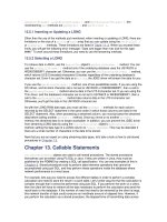
LAN as primarily a means of connecting computers. These multiservice
home networks support a broad variety of media and computing devices
as part of a single network. A multiservice home network is depicted in
Fig. 2-1.
1
Analysts project that the number of networked nodes in homes, includ-
ing both PC-oriented and entertainment-oriented devices, will top 80 mil-
lion by the year 2005. As can be inferred from Fig. 2-1, the multiservice
home network must accommodate a variety of types of traffic. The ideal
multiservice home LAN:
39
40
Part 1: Overview of Wireless High-Speed Data Technology
Supports differing traffic types such as low- and high-rate bursty
asynchronous data transfer, telemetry information, multicast
streaming audio and video, and interactive voice.
Provides sufficient bandwidth to support an increasing amount of
high-rate traffic both within the home and transiting the gateway.
Allows multiple types of devices to operate on the network without
interfering with one another.
Efficiently supports diverse devices with differing price, power, and
data rate targets.
Efficiently allocates spectrum and bandwidth among the various
networked devices.
Can economically provide a single gateway through which services
can be provisioned and devices can communicate outside the home.
Provides coverage throughout the home, preferably with a single
access point.
1
Popular wireless data networking protocols such as Bluetooth, IEEE
802.11, and HomeRF meet some, but not all, of the multiservice home
networking requirements. Furthermore, because the protocols were
developed independently, they do not easily interoperate with one another
and can cause significant mutual interference when functioning in the
same radio space. The 802.11a WLAN standard offers speed and robust-
ness for home networking that previous WLAN standards have not
offered. Although access to this bandwidth for home networking is rela-
tively recent, cost-effective chip sets have already been announced, such
as Atheros’ AR5000 802.11a chip set including an all-CMOS radio-on-a-
chip (ROC). However, devices such as cordless telephones, personal digi-
Network
interface
device
Broadband
access
Figure 2-1
A multiservice wireless
home network with
broadband access.
Chapter 2: Wireless Data Network Protocols
tal assistants (PDAs), and networked appliances do not require all of the
speed and features that 802.11a offers. An extension to these protocols
that allows less expensive, lower-power, lower-data-rate radios to inter-
operate with higher-speed, more complex 802.11a radios is presented in
this part of the chapter. The goal of this extension is to maintain high
overall efficiency while allowing scalability: the ability to create dedicated
radios with the capabilities and price points appropriate to each applica-
tion and traffic type.
Background: 802.11 PHY Layer
Wireless data networking systems can be best understood by considering
the physical (PHY) and media access control (MAC) layers separately. The
physical layer of 802.11a is based on orthogonal frequency-division multi-
plexing (OFDM), a modulation technique that uses multiple carriers to mit-
igate the effects of multipath. OFDM distributes the data over a large num-
ber of carriers that are spaced apart at precise frequencies.
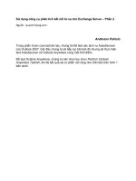
The 802.11a provides for OFDM with 52 carriers in a 20-MHz band-
width: 48 carry data, and 4 are pilot signals (see Fig. 2-2).
1
Each carrier is
about 300 kHz wide, giving raw data rates from 125 kbps to 1.5 Mbps per
carrier, depending on the modulation type [binary phase shift keying
(BPSK), quadrature PSK (QPSK), 16-quadrature amplitude modulation
(QAM), or 64-QAM] employed and the amount of error-correcting code
overhead (
1
⁄2 or
3
⁄4 rate).
NOTE The different data rates are all generated by using all 48 data
carriers (and 4 pilots).
OFDM is one of the most spectrally efficient data transmission tech-
niques available. This means that it can transmit a very large amount of
data in a given frequency bandwidth. Instead of separating each of the
52 subcarriers with a guard band, OFDM overlaps them. If done incor-
rectly, this could lead to an effect known as intercarrier interference
(ICI), where the data from one subcarrier cannot be distinguished unam-
biguously from their adjacent subcarriers. OFDM avoids this problem by
41
20-MHz OFDM channels in 5-GHz band
52 carriers total
20 MHz
One channel (detail)
Each carrier is ~300 kHz wide
Figure 2-2
The 802.11a PHY.
42
Part 1: Overview of Wireless High-Speed Data Technology
making sure that the subcarriers are orthogonal to each other by precisely
controlling their relative frequencies. In addition, coded OFDM is resis-
tant to channel impairments such as multipath fading or narrowband
interference. Because the coded information is spread across all the carri-
ers, if a subset of the carriers is lost, the information can be reconstructed
from the error correction bits in other carriers.
Background: 802.11 MAC Layer
Access methods for wireless data channels fall into three general cate-
gories: contention methods, polling methods, and time-division multiple
access (TDMA) methods. The 802.11a is based primarily on contention
methods, with some polling capabilities as well. Contention systems such
as IEEE 802.11 use heuristics (random backoff, listen-before-talk, and
mandated interframe delay periods) to avoid (but not completely elimi-
nate) collisions on the wireless data medium. IEEE 802.11 also employs a
beacon message that can be asserted by the access point and allows the
access point to individually poll selected stations for sending or receiving
data. The duration of the polling period is controlled by a parameter set
by the access point and contained within the beacon message.
Contention systems are well suited to asynchronous bursty traffic.
These systems work particularly well when the burst sizes are compara-
ble to the natural packet size of the medium, or small multiples of the
natural packet size. Slotted systems are well suited to isochronous appli-
cations that have a need for continuous channel bandwidth, although
they may have extra overhead in comparison to contention systems when
carrying asynchronous bursty traffic.
Another MAC layer consideration is whether there is a dedicated cen-
tral controller such as an access point (AP) or base station. The 802.11a
uses an AP, but has a fallback method for when there is no centralized
controller (ad hoc mode). However, the operation of the network is more
efficient with an AP present.
An Extension to 802.11a Is Needed
The 5-GHz 802.11a standard offers higher data rates and more capacity
than 802.11b. However, to provide a complete solution for wireless data
home networks, 802.11a needs to be extended to address remaining
challenges. For example, the present standard does not support differing
device/application types, nor does it enable a unified network that
allows a single gateway or access point to support all the devices within
a home. A cordless phone is a good example of such a device. It does not
Chapter 2: Wireless Data Network Protocols
require a high data rate, but must provide high-quality sound and error-
free transmission. As things stand now, there are only two ways to
implement the phone in a standard 5-GHz wireless data network. You
can make the phone a full 54-Mbps device and have it share time at a
low duty cycle. This is an expensive solution for a cordless phone and
draws high peak power while transmitting or receiving.
The second solution is to transmit at a data rate close to the cordless
phone’s natural rate, and make the rest of the network nodes wait for it
to get off the air. This is highly inefficient and greatly reduces the over-
all throughput of the network.
The best solution is to allow the cordless phone to transmit at its nat-
ural rate at the same time other nodes are transmitting at their natural
rates. Unfortunately, this type of operation is not supported under any
of the existing 5-GHz wireless data network standards. An extension to
802.11a that allows overlaying transmissions using OFDM techniques
has been proposed and is described later in the chapter.
The 5-GHz Unified Protocol
The 5-GHz Unified Protocol (5-UP) proposal extends the OFDM system to
support multiple data rates and usage models. It is not a new standard,
but an enhancement to the existing IEEE standard that would permit
cost-effective designs in which everything from cordless phones to high-
definition televisions and personal computers could communicate in a sin-
gle wireless multimedia network with speeds up to 54 Mbps. The 5-UP
achieves this by allocating the carriers within the OFDM signal on an indi-
vidualized basis. As with the background on the existing standards, the
5-UP can be described by examining its PHY layer first, and then the MAC
layer. Many of the elements of the MAC layer will be seen to be out-
growths of restrictions within the PHY layer.
5-UP PHY Layer
The 5-UP provides scalable communications by allowing different nodes to
simultaneously use different subsets of the OFDM carriers. This is intu-
itive, and can be seen as an advanced frequency-division multiple access
(FDMA) system. Most OFDM equipment can support this quite easily.
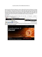
An example is shown in Fig. 2-3.
1
In this figure, the laptop, PDA, and
voice over IP (VoIP) phone are simultaneously transmitting to an access
point (not shown). The laptop device generates its OFDM signal using
an inverse fast Fourier transform (iFFT). It would be simple for this
device to avoid transmitting on some of the carriers by zeroing out some
43
44
Part 1: Overview of Wireless High-Speed Data Technology
of the inputs to the iFFT and using only the remaining inputs to trans-
mit data. Low-data-rate devices can then occupy the slots that were
omitted by the laptop. In the case shown in Fig. 2-3, the PDA makes
use of two of the omitted carriers, while the VoIP phone makes use
of one.
At the receiving side, the radio would look similar to that shown for the
laptop. All carriers can be simultaneously received by the access point and
recovered through its single FFT-based receiver. The access point must
then group the parallel outputs of the FFT into the separate streams.
Finally, when the access point transmits to the other nodes, it can use a
single iFFT to simultaneously create all the carriers. Each of the other
nodes can receive only its subset of carriers, discarding the carriers
intended for a different node.
The great advantage to this approach is that both the analog and dig-
ital complexity required in the radio scales with the number of carriers
that can be transmitted or received. In the ultimate case of just one car-
rier, the radio becomes a single-carrier biphase shift-keying (BPSK) or
quadrature PSK (QPSK) radio, transmitting at 1/52 the output power
required to achieve the same range with a full 52-carrier radio. Table 2-1
highlights the relative analog and digital complexity required to achieve
a given data rate.
1
The 5-UP enables the building of radios with a broad range of com-
plexity, which in turn results in a range of power and price points that
serve a number of different data-rate requirements, allowing all to func-
tion simultaneously and efficiently in a high-data-rate system. Table 2-2
lists examples of the data rates and applications that can be met using
various modulations and numbers of carriers.
1
5-UP PHY Layer Constraints
While the evolution from an OFDM system to an advanced frequency-
division multiple access (FDMA) system is intuitive, there are a number
of constraints required to make it work. These constraints come from
DAC
10 bits
Filter
DAC
10 bits
Filter
90
20 MHz
52 carriers
250 kb/s
250 kb/s
0
0
250 kb/s
250 kb/s
0
Carriers omitted by laptop
Laptop
PDA
VoIP
cordless
phone
*
Figure 2-3
The 5-UP can provide
scalable communica-
tions.
45
TABLE 2-1
Transmitter Power Based on Regulations for the Lower 100 MHz of the U.S. UNII Band
Transmitter
Transmitter
Power, Average, Power, Peak, mW
Data Rate No. of Carriers Modulation
mW
(Approximate) ADC/DAC
FFT Size
125 kbps
1
BPSK
0.8
1
4 bits
None
750 kbps
1
16-QAM 0.8
1.4
5 bits
None
1.5 Mbps
4
QPSK
3.2
4
5 bits
4
6 Mbps
8
16-QAM 6.4
8
6 bits
8
12 Mbps
16
16-QAM 12.8
16
7 bits
16
36 Mbps
48
16-QAM 40
48
8 bits
64
54 Mbps
48
64-QAM 40
48
8 bits
64
46
Part 1: Overview of Wireless High-Speed Data Technology
the close spacing of the carriers (required to achieve high efficiency) and
practical limitations in the design of inexpensive radio transceivers.
Narrowband Fading and Interference Control One disadvantage
to using the carriers independently is that narrowband interference or
fading can wipe out the complete signal from a given transmitter if it is
using just one or a few carriers. Under those conditions, no amount of
coding will allow the missing signal to be recovered.
Two solutions are well known to make narrowband signals more
robust. The first is to employ antenna diversity. Radios can be built that
can select between one of two antennas. If the desired carriers are in a
fading null at one antenna, then statistically they are not likely to be in
a null at the other antenna. Effective diversity gains of 8 to 10 dB are
normally observed for two antenna systems.
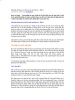
A second way to provide robustness to narrowband fading and inter-
ference is to “hop” the subcarriers in use over time. This approach will
work even for the case in which only one subcarrier is used at a time. For
example, the node could transmit on subcarrier 1 in the first time period,
and then switch to subcarrier 13 in the next period. Packets lost when
the node is on a frequency that has interference or fading could be
retransmitted after the next hop. Several such hopping nodes could be
supported at the same time, hopping between the same set of subcarriers
on a sequential basis. A similar arrangement could be used for nodes that
use multiple subcarriers simultaneously, hopping them all in contiguous
blocks, or spreading them out and hopping the entire spread of subcarri-
ers from one channel set to another over time (see Fig. 2-4).
1
A carrier allocation algorithm that is more intelligent than blind hop-
ping can also be implemented. Narrowband fading and interference are
likely to affect different nodes within a wireless data network differently
because of the various nodes’ locations. Thus, a given subcarrier may
TABLE 2-2
Data Rate and
Application Exam-
ples with Various
Modulations and
Numbers of Carriers
Data Rate Applications Carriers Modulation
125 kbps Cordless phone, remote 1 BPSK
control
1.5 Mbps High-fidelity audio 2 or 4 16-QAM or QPSK
12 Mbps MPEG2 video, DVD, 12, 16, or 32 64-QAM, 16-QAM, or
satellite, XDSL, cable QPSK
modem, data network
20 Mbps HDTV, future cable, 18 or 27 64-QAM or 16-QAM
or VDSL broadband
modem
Chapter 2: Wireless Data Network Protocols
work poorly for some of the nodes, but it might work well for other nodes.
The subcarriers could therefore be intelligently allocated, swapping the
assignments between nodes until all nodes are satisfied.
The 5-UP MAC
The 5-UP may readily be adapted to work with existing industry stan-
dard protocols such as 802.11a. Figure 2-5 shows a picture of the 5-UP
frame as it would be embedded into an 802.11a system.
1
In the figure,
the different rows represent different carriers, while the columns repre-
sent different slots in time.
To make the 5-UP work, three fundamental things are required.
First, there must be a way to carve out time during which the 5-UP
overlaid communication can take place. In the case of 802.11, this can be
done by using the point coordination function (PCF) beacon. The original
definition of 802.11 included two medium-access control mechanisms.
These are the distributed coordination function (DCF) and the PCF.
DCF is Ethernet-like, providing for random channel access based on a
listen-before-talk carrier sense multiple-access (CSMA) technique with
random backoffs. This is the most commonly used access mechanism in
current 802.11 equipment.
The PCF access mechanism is based on centralized control via polling
from the access point. In this access mode, all nodes are silent until they
are polled by the access point. When polled by the access point, they can
send a packet in return.
47
0
1
2
3
4
5
3
5
0
3
1
2
4
3
4
5
2
0
1
Figure 2-4
The progression of
carrier assignments
over subsequent
frames.
5-UP beacon 1 Carrier 1 Carrier 1
5-UP beacon 51 Carrier 51 Carrier 51
5-UP beacon 52 Carrier 52 Carrier 52
PCF beacon
CF-End beacon
802.11a
DCF
period
802.11a
DCF
period
One 5-UP time period
Downlink
period
Uplink
period
52
frequency
carriers
Figure 2-5
The 5-UP frame.
48
Part 1: Overview of Wireless High-Speed Data Technology
Two beacons are used to define the time during which the PCF access
mechanism is in operation (the contention-free period) rather than the
DCF mechanism. The PCF beacon announces to all the nodes that the
polling access period is beginning. When nodes receive this beacon, they
do not transmit unless they receive a poll from the access point that is
addressed specifically for them. The end of the PCF (contention-free)
period is signaled by a contention-free end beacon (CF-End).
In an 802.11 system, the contention-free periods are typically periodic,
allowing for nearly isochronous communication of some portion of the traf-
fic. The PCF beacon can be used to reserve a time period during which all
legacy nodes will remain silent and the 5-UP can operate. Once the PCF
beacon has been transmitted by the access point, all nodes must remain
silent as long as they are not requested to transmit by a valid poll mes-
sage. Because overlaid 5-UP traffic will not appear to be valid
poll messages, legacy nodes will remain silent throughout the 5-UP period.
The 5-UP-enabled nodes can then be addressed using the 5-UP without
interference from legacy nodes.
After the 5-UP period has ended, the access point can send an 802.11
CF-End message, as defined in the standard, to reactivate the 802.11 nodes
that were silenced by the initial PCF beacon. Following the CF-End mes-
sage, communication would return to the nonoverlaid 802.11a method.
In this manner, the channel can be time-shared between traditional
802.11a operation and 5-UP operation. Legacy nodes will participate only
in the 802.11a period, and will not transmit or receive any valid packets
during the 5-UP period. Nodes that can operate only during the 5-UP
period, such as nodes that can operate only on a subset of the carriers,
will not be able to transmit or receive during the 802.11a period, but will
be active during the 5-UP period. Finally, nodes that are able to handle
both 802.11a and 5-UP messages can transmit or receive in either period.
The access point can adjust the timing of the PCF and CF-End beacons to
balance the traffic requirements of 5-UP and legacy 802.11a nodes.
The second requirement for embedding the 5-UP into the 802.11a pro-
tocol is to ensure that all devices know when they need to transmit in
the 5-UP overlaid fashion and when to transmit according to the 802.11a
methods. For nodes that understand the 5-UP only, or can use only a
subset of the carriers, all communication outside of the 5-UP period will
be indecipherable and will appear as noise. However, when the 5-UP
period arrives, the 5-UP beacon transmitted at the beginning of this
period will be intelligible. The 5-UP beacon is transmitted on each carri-
er individually such that even a single-carrier device can receive and
understand it. This beacon includes information on the length of the 5-
UP period and when the next 5-UP period is scheduled. Once synchro-
nized, nodes that communicate only during the 5-UP period can sleep
during the 802.11a periods.
Chapter 2: Wireless Data Network Protocols
Nodes that do not understand the 5-UP will know not to try to trans-
mit during the 5-UP period, as described in the preceding. Nodes that
understand both the 5-UP and the 802.11a protocol can understand
all the packets that are transmitted, gaining information from both sets
of beacons and potentially transmitting and receiving during both periods of
operation.
Direct peer-to-peer communication or communication with the access
point can be allowed in the nonoverlaid period. However, during the 5-UP
overlaid period, only communication to or from the access point is allowed.
The third basic requirement is that 5-UP nodes must be able to request
service, and must be instructed which carriers, hopping patterns, and
time slots they should use. The 5-UP beacon is transmitted on each carrier
such that even a single-carrier node can interpret this beacon no matter
to which carrier it has tuned. The beacon includes information about
which carriers and time slots are available to request service or associate
with the network. As shown in Fig. 2-5, there are uplink slots (transmit-
ting to the access point) and downlink slots (receiving from the access
point). The node requesting service waits until it gets a response during a
downlink slot. The response includes the carriers and time slots that will
be allocated for traffic for that device. It also would indicate the hop pat-
tern and timing if the network is operating in a hopping mode.
Some information, such as the time reference and when the overlaid
communication period begins and ends, needs to be transmitted on each
carrier; however, other information such as which time slot is assigned
to which node for a given carrier is unique to each carrier. Information
unique to a given node (sleep/wake information) needs to be transmitted
on only one of the carriers assigned to that node.
Now, let’s discuss how TIA/EIA standard IS-856 cellular data (1xEV)
can be married with IEEE 802.11b wireless data to enable wide-area
Internet access for service providers and users. In other words, the lingua
franca of the Internet is TCP/IP, and wireless data devices are learning to
speak this language. But what is the “wireless data Internet?” There are
a number of different answers to this question. The question poses prob-
lems for equipment manufacturers, service providers, and users alike. You
desire seamless access to the Internet, and in order to have that, all these
different modes must operate transparently for users.
Wireless Data Protocol Bridging
Both 802.11 and the Telecommunications Industry Association/Electronics
Industry Alliance (TIA/EIA) IS-856 are wireless data networking proto-
cols. However, each meets different goals. Devices for short-range 802.11
49
50
Part 1: Overview of Wireless High-Speed Data Technology
wireless data networks are rapidly proliferating. Wireless data network
providers (carriers) are eager to deploy high-speed wireless data protocols
such as IS-856 that complement their wireless voice networks. The IS-856
standard is integrated into the protocols for code-division multiple access
(CDMA) networks. Finding an effective means to connect 802.11 devices to
increasingly available high-data-rate cellular networks answers the need
of users for 802.11 devices to take advantage of the eventual ubiquity of
high-speed cellular networks.
The 802.11 and IS-856 protocols have similar architectures. Wireless
data stations are untethered. Both use similar modulation techniques
for moving bits of data through the wireless medium. Both provide
medium access control (MAC) to manage the physical and data link lay-
ers of the open systems interconnect (OSI) protocol model. Access points
mediate access to other networks. Each has protocols for handing off
between access points a station’s logical connections as stations move
into different coverage regions. Both are well adapted to support higher
layers of the TCP/IP protocol stack.
However, significant differences exist as well. The differences arise
from the different design goals these protocols serve. The 802.11 stan-
dard is designed to build short-range wireless local-area networks
(WLANs), where the maximum distance between stations is on the order
of 100 m. While IS-856 supports LANs, the range over which stations
communicate is tens of kilometers. The IS-856 standard is designed to be
an integral part of a cellular communication network that operates in
licensed frequency bands assigned specifically for cellular communica-
tion. Networks of 802.11 devices use unlicensed frequency bands and
must work in spite of the possibility of other nearby devices using the
same radio spectrum for purposes other than data communication.
These differences, principally the difference in range, fostered the idea
that these two wireless data systems could be combined to complement
each other. Another factor behind this idea is the proliferation of 802.11-
capable devices and the desire of their users to connect to the Internet via
their Internet service provider (ISP). Thus, this part of the chapter up to
this point has demonstrated how 802.11 networks and IS-856 networks
can be bridged to facilitate user demand for this connectivity as they
range through an IS-856 network with their 802.11 device.
Connecting the two protocols is quite straightforward. It can be done
simply because these protocol designs complement each other in key
ways. This part of the chapter provides overviews of how IS-856 and
802.11b manage the wireless data medium. Following the overview, the
technique used to bridge the protocols is described. This part of the chap-
ter concludes with some suggestions on how an ISP can take advantage of
these techniques to offer wide-area access to its subscribers who are using
802.11 devices.
Chapter 2: Wireless Data Network Protocols
Overview of 802.11 Architecture
The introduction to this part of the chapter listed a number of similari-
ties and differences between IS-856 networks and 802.11 networks. The
differences are primarily due to the way in which each wireless data
protocol is used. Networks of 802.11 devices are short-range wireless
data networks. Today, typical applications for 802.11 protocols provide
wireless data access to TCP/IP networks for laptop computers. The
802.11 protocols aren’t limited to this kind of application. Any group of
devices designed to share access to a common short-range communica-
tion medium can be built on 802.11’s services. In the future, devices
designed for particular tasks that incorporate communication with other
nearby devices will be able to take advantage of 802.11’s services in ad
hoc networks. Some of these devices may simultaneously be part of the
more structured environment of the Internet. This will have important
implications when a single user or group of nearby users has a variety of
devices that could interact for the benefit of their owners.
Devices able to take advantage of a wireless data network will use
TCP/IP protocols as their means to exchange information with other
devices. Because 802.11 defines MAC protocols, which correspond to the
data link and physical layers of the OSI model, 802.11 is well suited to
provide the basic connection on which the rest of the TCP/IP protocol
stack depends.
This aspect of 802.11 enables it to fit neatly with IS-856 networks. For
example, an IS-856 network could easily provide the backbone needed to
connect a number of separate 802.11 networks into a single network
domain. This idea is explored later when the particular architecture used
for the IETF network is described.
IEEE MAC Protocol for Wireless Data LANs
One of the fundamental design goals for 802.11 is to provide services
that are consistent with the services of 802.3 networks. This makes the
peculiarities of wireless data communication irrelevant to higher layers
of the protocol stack. The 802.11 MAC protocols take care of the house-
keeping associated with devices moving within the 802.11 WLAN. From
the point of view of the IP layer, communication via wireless data with
802.11 is no different from communication over an 802.3 data link, fiber,
asynchronous transfer mode (ATM), or any other data link service.
Because these different media are capable of different data rates, users
can perceive differences in performance. But any well-designed applica-
tion will operate successfully over all these media. This greatly reduces
complexity for application designers. Reduced complexity results in
51
52
Part 1: Overview of Wireless High-Speed Data Technology
more reliable and more robust applications, more rapid development by
designers, and broader utility for users.
Designed for Multiple Scenarios
The fundamental organizational unit of an 802.11 network is called a
basic service set (BSS). The members of a BSS are the wireless data sta-
tions that share a specific 802.11 WLAN. How a BSS connects to other
networks defines the variants.
A BSS not connecting to another network is termed an independent
BSS or iBSS (see Fig. 2-6).
2
An iBSS uses MAC protocols to establish
how its members share the medium. There can be no hidden nodes in an
iBSS. Each member must be able to communicate directly with all other
members without relays. An iBSS is ideal for a collection of personal
devices that move with the owner. For example, a PDA, laptop, cell
phone, CD or DVD player, or video and/or audio recorder could be mem-
bers of an individual’s personal network of communication devices. An
802.11 network connecting them would provide an individual user with
a rich array of ways to communicate with others. Another example
might be a coffee maker, alarm clock, lawn sprinkler controller, home
security cameras, home entertainment systems, and a personal computer.
Figure 2-6
Independent basic
service set.
Chapter 2: Wireless Data Network Protocols
A network made up of these devices could turn on the coffee maker
when the alarm goes off in the morning. It would allow a homeowner to
water the grass from an easy chair, and make sure it is not watering the
sidewalk, or turn the sprinklers on a burglar while calling the police and
playing recordings of large dogs barking.
When a BSS connects with another network via an access point, it is
termed an infrastructure BSS. Because this is the most common configu-
ration today, the acronym BSS usually implies an infrastructure BSS.
The access point is both a member of the BSS and mediates access to
other networks on behalf the rest of the BSS. Generally, the members of
the BSS beside the access point are personal computers. To facilitate cov-
erage of a campus within the same 802.11 network, a group of BSSs,
called an extended service set (ESS), define how access points hand off
connections for members of the network as stations move between access
points. The access points are connected by backbone links that provide
the medium for the hand-off protocol (see Fig. 2-7).
2
The 802.11 standard supports simultaneous existence of iBSS and
BSS networks. It provides means for labeling networks and conditioning
access so they can operate without interfering with each other. It is
entirely reasonable that the computers mentioned in the iBSS examples
in the preceding could participate simultaneously in a private 802.11
network and an infrastructure 802.11 network providing Internet
access. While this idea has fascinating possibilities, further discussion is
beyond the scope of this chapter.
53
BSS
Access
point
Figure 2-7
Extended service set.
54
Part 1: Overview of Wireless High-Speed Data Technology
MAC Layer Protocols
The 802.11 standard consists of several MAC layer protocols to provide
the variety of services necessary for the kinds of wireless data networks
just described. A Beacon protocol enables a BSS or an iBSS to organize
its communication. The Beacon information contains the network label
information so 802.11 devices can discover the networks that exist with-
in range of their antennas. The Beacon establishes the timing intervals
of the network. Timing intervals mediate how stations access the medium.
For an iBSS, once timing and network identity are determined, stations
may exchange data. For a BSS, there are two additional groups of services
to manage traffic.
Distribution Services and Station Services
The nine services for a BSS are grouped into distribution services and sta-
tion services. There are five distribution services and four station services.
Distribution Services Distribution services manage traffic within a
BSS and transfer traffic beyond the BSS. They provide roaming capabil-
ity so a wireless data station can move between the BSSs in an ESS.
The five services are association, reassociation, disassociation, distribu-
tion, and integration.
Association creates a logical connection between a wireless data sta-
tion and the access point. Once association is established, the access
point will deliver, buffer, or forward traffic for a wireless data station.
The association service is used when a wireless data station first joins a
BSS or when a sufficiently long enough period has elapsed with no com-
munication between the access point and the wireless data station.
Reassociation is similar to association. A wireless data station uses
reassociation when moving between access points. A wireless data sta-
tion moving into an access point’s coverage notifies the new access point
with a reassociation request identifying the access point previously serv-
ing the wireless data station. The new access point then contacts the
prior access point for any traffic that has been buffered for the wireless
data station.
Either the wireless data station or the access point can use disassocia-
tion. A wireless data station sends a disassociation message when it is
leaving the BSS. An access point may send a disassociation message to a
wireless data station if it is going off line or has no resources to handle
the wireless data station. In the latter circumstance, a wireless data sta-
tion may attempt to associate with a different access point, provided there
is one in range.
Chapter 2: Wireless Data Network Protocols
Access points use the distribution service to forward frames received
from a wireless data station in its BSS. Frames may be forwarded to
another station within the BSS, to another station within an ESS, or to a
router for delivery to a destination outside the WLAN.
Integration and distribution provide a portal to non-802.11 networks.
Integration takes an 802.11 frame and recasts it as a frame for a differ-
ent type of data link service such as Ethernet.
Station Services While distribution services enable wireless data
stations and access points to establish communication, station services
grant permission to use a BSS and accomplish delivery of data in the
BSS. The four services are authentication, deauthentication, privacy,
5
and data delivery.
Authentication, deauthentication, and privacy are potentially valu-
able. However, the current definition of these services cannot be relied
on to protect access to the WLAN. In lieu of these limitations, there are
alternative means, such as IPSec, to ensure the integrity of IP traffic
sent across an 802.11 WLAN. More detailed discussion of these issues is
beyond the scope of this chapter.
Of these services, data delivery is the most important. It provides
reliable delivery of datagrams while minimizing duplication and
reordering. It is the essential service for moving data across the WLAN.
Data delivery, distribution, and management services are the essential
services provided by the MAC layer of 802.11.
802.11: Versatile Wireless Data Environment
The MAC protocols provided by 802.11 permit the creation of a variety
of short-range wireless data networks. These networks range from ad
hoc collections of stations to integral subnets of a complex internetwork-
ing structure. The flexibility of 802.11 may well obviate the need for
other protocol stacks for personal devices. Regardless, 802.11’s easy
adaptability for TCP/IP networking has proved its value for large com-
munities. It is for one such large community that the Internet Engineer-
ing Task Force (IETF), combining the strengths of 802.11 and IS-856,
proved to be especially valuable.
An Overview of IS-856 Access Network
Architecture
This overview describes how the wireless data station and the access
network provide transparent data transmission for the logical sessions
55
56
Part 1: Overview of Wireless High-Speed Data Technology
between the wireless data station and the Internet. The description is
based on a prototype implementation of the architecture. A scalable
implementation would differ in some respects from the prototype, partic-
ularly with regard to methods for authentication and authorization of
wireless data stations. The description notes those details and offers
alternatives more suitable for commercial implementation.
CDMA cellular networks are spread-spectrum packet radio networks.
Originally, the CDMA protocol was designed for efficient transmission of
packets carrying voice data. Voice has different constraints from effi-
cient data transmission. Voice transmission minimizes delay times at
the cost of some data fidelity. The human ear is more tolerant of a little
distortion than it is of delay. For data transmission, nearly the reverse is
true. Errors in data bits increase packet retransmission, and that hurts
overall network throughput.
In a CDMA network, the base station sends data to wireless data sta-
tions over the forward link. Wireless data stations use the reverse link
to communicate to the base station. The IS-856 standard uses CDMA’s
reverse link packet structure, retaining compatibility with voice traffic.
The forward link packet structure is different, but the modulation tech-
niques are the same, preserving compatibility in the forward link. How-
ever, management techniques for voice traffic and for data traffic differ
considerably. A voice call consists of a single CDMA connection during
which the call begins and ends. Packet data transmission comprises
multiple CDMA connections, so that the CDMA network is used only
when the wireless data station must exchange data with the rest of the
network. A single logical network session (a browser session or an e-mail
exchange) will consist of a number of CDMA connections.
In the prototype IS-856 system all wireless data stations were known,
so registration of the wireless data station in the network was simpli-
fied. In a commercial system, IS-856 systems would use the Remote
Authentication Dial-In User Service (RADIUS) to manage the registra-
tion and configuration information a particular access network would
need. RADIUS is not the technique used to register cellular phones in
CDMA networks. The carrier would unify its accounting and billing for
data upstream of the systems by using RADIUS with other systems
used to account for voice traffic.
The RADIUS protocol is a means to authenticate connections to a
data network and optionally provide configuration information to the
device making the connection. When a user of a wireless data station
begins a session with an ISP, the wireless data station and a network
access server (NAS) exchange a series of messages that identify the
user, and obtain parameters configuring the Point-to-Point Protocol
(PPP) session used between the station and the access network. The net-
work access server may rely on databases further upstream for authen-
tication information it needs when the station attempts to connect.
Chapter 2: Wireless Data Network Protocols
Asymmetric Data Paths
To provide maximum data throughput for all wireless data stations in the
network, IS-856 uses asymmetric data paths. This is not unlike the asym-
metry between forward and reverse links in CDMA voice systems. By tak-
ing this approach to a packet data network, it is possible to provide higher
forward link burst rates than reverse link data rates. The user model for
wireless data stations assumes reverse link data demand is similar to
demand at the terminals of wired networks. The forward link to the wire-
less data station is capable of transmitting bursts up to 2.4 Mbps. The
reverse link provides a constant data rate of up to 153.6 kbps for each sta-
tion. These data rates are comparable to those typically found on cable
networks such as Time Warner’s Road Runner service or Cox@Home.
Access Network and Wireless Data Stations
The carrier’s access network mediates connections between wireless
data stations and the Internet by providing access points in each sector.
The access network is a private network, invisible and transparent from
the point of view of devices connected to the wireless data station or
from the Internet beyond the access network. Access networks manage
the IP space for all wireless data stations in the carrier’s service area.
Besides transporting data, the access network includes monitoring and
maintenance capabilities.
The access network and the wireless data station use PPP as their
data link protocol. PPP is carried over the radio channel using the Radio
Link Protocol (RLP) of IS-856. RLP minimizes data loss and packet
retransmission in order to provide an interface to the wireless data
medium with error rates that meet or exceed the requirements for ade-
quate PPP performance.
In the prototype, each wireless data station manages a local subnet.
This subnet is part of the IP space assigned to the prototype system, not
part of the access network. In a commercial implementation using the
same approach, the subnet managed by the wireless data station would
be part of an ISP’s IP space. Using the Dynamic Host Configuration Pro-
tocol (DHCP), the wireless data station distributes the IP space it man-
ages, and transfers TCP/IP traffic between the devices, the wireless data
station services, and the access point. Because the wireless data station
handles the PPP connection, downstream devices don’t need to. They
simply function as they would ordinarily in a TCP/IP LAN. The wireless
data station and access point cooperate to shield devices from the PPP
session and to permit persistent TCP/IP sessions, independent of the
CDMA connections. This helps optimize the use of the CDMA network
resources in a way that is transparent to the user.
57
58
Part 1: Overview of Wireless High-Speed Data Technology
Access Network Architecture
Figure 2-8 shows the connection between a wireless station (WS in the
figure) and the access network, as well as the access network’s internal
structure.
2
The access network consists of several subsystems. The prin-
cipal systems are the consolidation router, modem pool controller (MPC),
and access point. User Datagram Protocol/Internet Protocol (UDP/IP) is
used within the access network to connect subsystems. These will be
described next. While this is a description of a prototype architecture,
most of the same components and functions must be present in a com-
mercial system. Because this is a prototype, configuration information
storage
7
and maintenance are simplified.
The consolidation router creates the boundary between the access
network and the rest of the Internet. It provides routing information to
the Internet for all wireless data stations managed by the access net-
work. It also routes traffic within the access network, ensuring that pri-
vate traffic stays within the access network. Routes for user devices to
the Internet are derived from information maintained by the MPC.
The MPC is the heart of the access network. It houses the configura-
tion server (CS), overhead manager (OHM), and a set of selector functions
(SFs). The MPC uses the OHM and SFs to manage the state of wireless
data stations within all of the cells served by the access network. The
OHM’s primary role is to assign an SF for use during a wireless data sta-
tion session. In the prototype, the OHM also delivers configuration infor-
mation it obtains from a static database in the configuration server. In a
commercial system, the configuration server would interact with the
RADIUS authentication, authorization, and accounting (AAA) server to
obtain the necessary information for its database. When a wireless data
station registers with an access network (via some access point), the
access point notifies the OHM about the wireless data station. The OHM
assigns an SF to manage the wireless data station connection. In a com-
mercial implementation, the SFs may retrieve wireless data station para-
meters from either the configuration server database or directly from the
AAA server. The SF cooperates with the wireless station to maintain PPP
state. The SF encapsulates the PPP packet in RLP, and then forwards it
via UDP to the access point. The SF also updates the consolidation router
with current routing information for the wireless data station. When a
wireless data station moves between access points by moving into a new
sector, the SFs for each access point update the wireless data station
routes for the consolidation router.
An IS-856 access point divides into two structures, a local router and
modulation equipment connecting the access network to the cellular net-
work. An access point shares its modulation equipment among a number
of wireless data stations. Over time, the wireless data stations served by
59
Internet
PC
PC
Hub
WS
PC
PC
Hub
WS
Antenna
Antenna
RF
RF
RF
MPT
MPT
MPT
FLM/
RLM
FLM/
RLM
FLM/
RLM
Mgr
Router
Router
Router
OpCenter
Boot and
config svr
MPC
OHM and
SFs
Access point
Access network
Wireless station
network
Consolidation
router
Hub
Mgr
Mgr
Figure 2-8 The access network.
60
Part 1: Overview of Wireless High-Speed Data Technology
an access point will change. The local router within the access point
enables the modulation equipment to connect to the rest of the access
network regardless of how resources are assigned to wireless data sta-
tions. The modulation equipment consists of pairs of forward link mod-
ules/reverse link modules (FLMs/RLMs) and an RF adapter. Collectively,
this is called the modem pool transceiver (MPT). Each FLM or RLM is
an IP device on the access network LAN. The RF adapter connects
FLMs and RLMs to the RF system of the CDMA base station.
An FLM receives packets destined for wireless data stations. It pro-
vides the network and data link layer interface performing intermediate
modulation of the data. After the intermediate-frequency (IF) stage, it
hands the data stream to the RF adapter for broadcast in the cell sector.
An RLM performs the inverse process. It receives an IF stream from the
RF adapter, demodulates the data, and forms it into a packet, forward-
ing it to the SF.
Figure 2-9 shows how the access network uses UDP to encapsulate
packets that are exchanged between the wireless data station and the
Internet.
2
The IP datagram contains the user data flowing to and from
the mobile node. The other protocol layers in the diagram show the
encapsulation used to make the access network transparent to the Inter-
net and to devices connected to the wireless data station. An IS-856 sys-
tem preserves the PPP state between a wireless data station and an SF.
This must be accomplished despite movement of wireless data stations
between sectors and, consequently, between access points. The access
network preserves this information by using UDP to wrap the entire
packet down to the RLP layer. If a wireless data station changes access
points, the SF updates its internal route to the new FLM/RLM. In this
way, the SF and the wireless data station can maintain PPP state, regard-
less of how the wireless data station moves between sectors.
1 ϫ EV data session protocol flow
IP
Ethernet
IP
Ethernet
IP
Ethernet
PPP
RLP
HDR air interface
IP
PPP
RLP
UDP
IP
Ethernet
Mobile
nodes
Wireless
station
Access
point
AP router
7206
Internet
switch
SFs
Packet access
to Internet,
SPs and
customers
Consolidated router
contains all routes to
access terminals
Route updates
Figure 2-9
Access network pro-
tocol flow.
Chapter 2: Wireless Data Network Protocols
Forty-Ninth IETF Meeting Network
The IETF relies heavily on Internet communication for developing the
protocols that are essential for the smooth operation of the Internet and
for protocols for new services that can be provided over the Internet. The
IETF meets three times yearly for face-to-face working group meetings
to assist the work carried out by members over the Internet. An essen-
tial part of every IETF meeting is the increasingly misnamed “terminal
room.” The terminal room is a LAN created for the meeting to provide
Internet access to attendees, and to members who cannot attend in per-
son. Until recently, the LAN for each meeting provided wired access
throughout the meeting areas of the hotel where meetings are held. The
last few meetings have experienced an explosion in demand for 802.11
wireless data access as more attendees employ 802.11 wireless data net-
works at home. As a result, attendees have come to expect 802.11 cover-
age throughout the meeting areas of the main hotel.
As the number of people attending IETF meetings has grown, the
meeting hotels have no longer been able to provide enough hotel rooms
for all the attendees. Secondary hotels are used for the overflow. However,
extending the meeting network to the secondary hotels has not been
possible, putting attendees staying at the secondary hotels at a distinct
disadvantage.
The design of the network for the forty-ninth meeting in San Diego
demonstrated a solution for the access problem in the secondary hotels,
provided that attendees in the secondary hotels had 802.11 cards for
their laptop computers. By combining a prototype IS-856 network with
802.11 access points in these hotels, adequate access for those attendees
was provided (see Fig. 2-10).
2
An 802.11 BSS was installed in each secondary hotel. The 802.11
access point was connected to a prototype Qualcomm IS-856 wireless
61
IS-856
network
Wireless
station
Ethernet
802.11 access
point
Figure 2-10
Hotel network con-
nection.