netscreen concepts examples vpns phần 3 doc
Bạn đang xem bản rút gọn của tài liệu. Xem và tải ngay bản đầy đủ của tài liệu tại đây (236.8 KB, 27 trang )
&KDSWHU3XEOLF.H\&U\SWRJUDSK\ &KHFNLQJIRU5HYRFDWLRQ8VLQJ2&63
1HW6FUHHQ&RQFHSWV([DPSOHV²9ROXPH931V
6SHFLI\LQJ(LWKHU&5/RU2&63IRU5HYRFDWLRQ&KHFNLQJ
To specify the revocation check method (CRL, OCSP, both, or none) for a certificate of a particular CA, use the
following CLI syntax:
ns-> set pki authority id_num cert-status revoc { CRL | OCSP | all | none }
where id_num is the identification number for the certificate.
The following example specifies OCSP revocation checking.
ns-> set pki authority 3 cert-status revocation-check ocsp
The ID number 3 identifies the certificate of the CA.
'LVSOD\LQJ&HUWLILFDWH5HYRFDWLRQ6WDWXV$WWULEXWHV
To display the revocation check attributes for a particular CA, use the following CLI syntax:
ns-> get pki authority id_num cert-status
where id_num is the identification number for the certificate issued by the CA.
To display the revocation status attributes for the CA that issued certificate 7:
ns-> get pki authority 7 cert-status
6SHFLI\LQJWKH85/RIDQ2&635HVSRQGHUIRUD&HUWLILFDWH
To specify the URL string of an OCSP responder for a particular certificate, use the following CLI syntax:
ns-> set pki authority id_num cert-status ocsp url url_str
To specify the URL string of an OCSP responder (http:\\192.168.10.10) for the CA with certificate at index 5, use the
following CLI syntax:
ns-> set pki authority 5 cert-status ocsp url http:\\192.168.10.10
To remove the URL (http:\\192.168.2.1) of a CRL server for a certificate 5:
ns-> unset pki authority 5 cert-status ocsp url http:\\192.168.2.1
&KDSWHU3XEOLF.H\&U\SWRJUDSK\ &KHFNLQJIRU5HYRFDWLRQ8VLQJ2&63
1HW6FUHHQ&RQFHSWV([DPSOHV²9ROXPH931V
5HPRYLQJ&HUWLILFDWH5HYRFDWLRQ&KHFN$WWULEXWHV
To remove all attributes related to a certificate revocation check for a CA that issued a particular certificate, use the
following syntax:
ns-> unset pki authority id_num cert-status
To remove all revocation attributes related to certificate 1:
ns-> unset pki authority 1 cert-status
&KDSWHU3XEOLF.H\&U\SWRJUDSK\ &KHFNLQJIRU5HYRFDWLRQ8VLQJ2&63
1HW6FUHHQ&RQFHSWV([DPSOHV²9ROXPH931V
1HW6FUHHQ&RQFHSWV([DPSOHV²9ROXPH931V
5RXWLQJ%DVHG931V
The configuration of a NetScreen device for virtual private network (VPN) support is particularly flexible. In
ScreenOS releases prior to 3.1.0, VPN tunnels are treated as objects (or building blocks) that together with source,
destination, service, and action, comprise a policy that permits VPN traffic. (Actually, the VPN policy action is
tunnel, but the action permit is implied, if unstated). In ScreenOS 3.1.0, the concept of a VPN tunnel shifted. In
addition
1
to the previous notion of a tunnel as an object used to build policies—see Chapter 4, “Policy-Based VPNs”
on page 123—a tunnel can also be viewed as a network resource used to transport traffic. Thus, you can consider a
tunnel as a means for delivering traffic between points A and B, and a policy as a method for either permitting or
denying the delivery of that traffic. Simply put, ScreenOS allows you the freedom to decouple the regulation of traffic
from the means of its delivery.
This chapter presents an overview and offers examples of the following routing-based VPN concepts:
• “Tunnel Interfaces” on page 48
– “Example: Tunnel Bound to Tunnel Interface” on page 49
– “Example: Deleting a Tunnel Interface” on page 57
• “LAN-to-LAN VPNs” on page 58
– “Example: Routing-Based LAN-to-LAN VPN, Manual Key” on page 59
– “Example: Routing-Based LAN-to-LAN VPN, AutoKey IKE” on page 70
– “Example: Routing-Based LAN-to-LAN VPN, Dynamic Peer” on page 76
• “Dialup-to-LAN VPN, Dynamic Peer” on page 92
– “Example: Routing-Based Dialup-to-LAN VPN, Dynamic Peer” on page 93
• “Hub-and-Spoke VPNs” on page 103
– “Example: Hub-and-Spoke VPNs” on page 104
• “Back-to-Back VPNs” on page 111
– “Example: Back-to-Back VPNs” on page 112
1. ScreenOS releases after 3.1.0 continues to support pre-ScreenOS 3.1.0 VPN configuration concepts and methods.
&KDSWHU5RXWLQJ%DVHG931V 7XQQHO,QWHUIDFHV
1HW6FUHHQ&RQFHSWV([DPSOHV²9ROXPH931V
7811(/,17(5)$&(6
When you configure the remote gateway for a VPN tunnel, you must also specify a security zone interface as the
local gateway
2
. Beyond the VPN tunnel termination points (the local and remote gateways), you can also configure
tunnel interfaces in either a security zone or in a tunnel zone through which the NetScreen device directs traffic to
and from the VPN tunnel
3
. You can bind a VPN tunnel to a specific numbered (with IP address/netmask) or
unnumbered (without IP address/netmask) tunnel interface in a security zone. If the tunnel interface is unnumbered,
it borrows the IP address from the interface of the security zone in which you created it. Now you have a VPN tunnel
that is bound both to a tunnel interface and to a local security zone interface.
Conceptually, you can view VPN tunnels as pipes that you have laid. They extend from the local device to remote
gateways, and the tunnel interfaces are the openings to these pipes. The pipes are always there, available for use
whenever the routing engine directs traffic to one of their interfaces.
2. Your IKE peer uses the IP address of your local gateway interface (or outgoing-interface) when configuring the remote gateway on his NetScreen device.
3. If you do not specify a tunnel interface, the tunnel uses the default interface for the security zone.
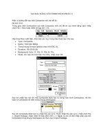
When a numbered tunnel interface is in a tunnel zone, you cannot bind a VPN
tunnel to the tunnel interface. You can only bind a tunnel to the tunnel zone.
This allows multiple tunnel interfaces to link to a single tunnel, or multiple
tunnels to link to a single tunnel interface. In such cases, you must create a
policy-based VPN configuration.
When a tunnel interface is in a security zone, you must bind a VPN tunnel to
the tunnel interface. Doing so allows you to create a routing-based VPN
configuration.
The tunnel interface can be numbered or unnumbered. If it is unnumbered, the
tunnel interface borrows the IP address from the security zone interface. Note:
Only a numbered tunnel interface (that is, an interface with an IP address and
netmask) can support policy-based NAT.
When a numbered tunnel interface is in a security zone and is the only interface
in that zone, you do not need to create a security zone interface. In this case,
the security zone supports VPN traffic via the tunnel interface, but no other kind
of traffic.
Security
Zone
Tunnel
Zone
Tunnel
Interfaces
Security Zone
Interfaces
VPN Tunnel
VPN Tunnel
VPN Tunnel
Numbered
Numbered or
Unnumbered
Security
Zone
Numbered
&KDSWHU5RXWLQJ%DVHG931V 7XQQHO,QWHUIDFHV
1HW6FUHHQ&RQFHSWV([DPSOHV²9ROXPH931V
Generally, assign an IP address to a tunnel interface if you want the interface to support policy-based NAT. For
more information about VPNs and policy-based NAT, see “Tunnel Zones and Policy-Based NAT” on page 202. You
can create a numbered tunnel interface in either a tunnel zone or security zone.
If the tunnel interface does not need to support policy-based NAT, and your configuration does not require the tunnel
interface to be bound to a tunnel zone, you can specify the interface as unnumbered. You must bind an unnumbered
tunnel interface to a security zone; you cannot bind it to a tunnel zone. You must also specify an interface bound to
that security zone whose IP address the unnumbered tunnel interface borrows.
([DPSOH7XQQHO%RXQGWR7XQQHO,QWHUIDFH
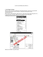
In this example, you configure a VPN tunnel between the corporate site and a branch office. The tunnel has the
following characteristics:
• The VPN tunnel is bound to a tunnel interface named tunnel.1.
• The Untrust zone is bound to the untrust-vr, not the trust-vr.
• AutoKey IKE VPN using a preshared key (netscreen1), Main mode, the security level predefined as
“Compatible” for both Phase 1 and Phase 2 proposals
• The interface specified as the local gateway on the corporate site is 210.1.1.1. (The branch office uses this
address as the remote gateway in its IKE configuration.)
• The NetScreen device at the corporate site is running ScreenOS 4.0.0.
• The NetScreen device at the remote site is running a version of ScreenOS earlier than 3.1.0.
Note: The security zone interface that you specify must be in the same zone to which you have bound the tunnel
interface.
Note: Only the configuration for the corporate end of the tunnel is given below. For information on configuring a
NetScreen device running pre-USGA ScreenOS, see the NetScreen Concepts & Examples ScreenOS Reference
Guide for the version of ScreenOS that is appropriate for your device.
&KDSWHU5RXWLQJ%DVHG931V 7XQQHO,QWHUIDFHV
1HW6FUHHQ&RQFHSWV([DPSOHV²9ROXPH931V
:HE8,
6HFXULW\=RQHVDQG9LUWXDO5RXWHUV
1. Network > Interfaces > Edit (for ethernet1/2): Enter the following, and then click OK:
IP Address/Netmask: 0.0.0.0/0
Manage IP: 0.0.0.0
2. Network > Interfaces > Edit (for ethernet1/2): Enter the following, and then click OK:
Zone Name: Null
3. Network > Zones > Edit (for Untrust): In the Virtual Router Name drop-down list, select untrust-vr, and then
click OK.
Zone: Sales
10.1.1.1/24
eth2/1
Zone: Untrust
210.1.1.1/24
eth1/2
Branch1
10.2.1.0/24
Gateway
211.2.2.2/24
tunnel.1
Default Gateway
210.1.1.254
trust-vr Routing Domain
untrust-vr Routing Domain
VPN tunnel:
to_branch1
Note: The castle icon represents
a security zone interface.
The NetScreen device sends the encapsulated VPN
traffic to the external router acting as the default gateway.
&KDSWHU5RXWLQJ%DVHG931V 7XQQHO,QWHUIDFHV
1HW6FUHHQ&RQFHSWV([DPSOHV²9ROXPH931V
4. Network > Interfaces > Edit (for ethernet1/2): Enter the following, and then click OK:
Zone Name: Untrust
5. Network > Zones > New: Enter the following, and then click OK:
Name: Sales
Virtual Router Name: trust-vr
,QWHUIDFHV²=RQHVDQG7XQQHO
6. Network > Interfaces > Edit (for ethernet2/1): Enter the following, and then click OK:
Zone Name: Sales
IP Address/Netmask: 10.1.1.1/24
7. Network > Interfaces > Edit (for ethernet1/2): Enter the following, and then click OK:
Zone Name: Untrust
IP Address/Netmask: 210.1.1.1/24
8. Network > Interfaces > Tunnel IF New: Enter the following, and then click OK:
Tunnel Interface Name: tunnel.1
Zone: Untrust
Unnumbered: (select)
Interface: ethernet1/2(Untrust)
4
4. The source interface must be in the same zone to which the tunnel interface is bound; in this case, the Untrust zone. The unnumbered tunnel interface
borrows the IP address of the specified security zone interface.
&KDSWHU5RXWLQJ%DVHG931V 7XQQHO,QWHUIDFHV
1HW6FUHHQ&RQFHSWV([DPSOHV²9ROXPH931V
931
9. VPNs > AutoKey IKE > New: Enter the following, and then click OK:
VPN Name: to_branch1
Security Level: Compatible
Remote Gateway: Create a Simple Gateway: (select)
Gateway Name: branch1
Type: Static IP (select), IP Address: 211.2.2.2
Preshared Key: netscreen1
Security Level: Compatible
Outgoing Interface: ethernet1/2
5
> Advanced: Enter the following advanced settings, and then click Return to
return to the basic AutoKey IKE configuration page:
Security Level: Compatible
Replay Protection: (select)
Bind to: Tunnel Interface: tunnel.1
Proxy-ID: (select)
Local IP/Netmask: 10.1.1.0/24
Remote IP/Netmask: 10.2.1.0/24
Service: ANY
5. The outgoing interface does not have to be in the same zone to which the tunnel interface is bound.
&KDSWHU5RXWLQJ%DVHG931V 7XQQHO,QWHUIDFHV
1HW6FUHHQ&RQFHSWV([DPSOHV²9ROXPH931V
$GGUHVVHV
10. Objects > Addresses > List > New: Enter the following, and then click OK:
Address Name: sales-any
IP Address/Domain Name:
IP/Netmask: (select), 10.1.1.0/24
Zone: Sales
11. Objects > Addresses > List > New: Enter the following, and then click OK:
Address Name: branch1
IP Address/Domain Name:
IP/Netmask: (select), 10.2.1.0/24
Zone: Untrust
5RXWHV
12. Network > Routing > Route Table > trust-vr New: Enter the following, and then click OK:
Network Address/Netmask: 0.0.0.0/0
Next Hop Virtual Router Name: (select), untrust-vr
13. Network > Routing > Route Table > untrust-vr New: Enter the following, and then click OK:
Network Address/Netmask: 10.2.1.0/24
Gateway: (select)
Interface: tunnel.1
Gateway IP Address: 0.0.0.0
&KDSWHU5RXWLQJ%DVHG931V 7XQQHO,QWHUIDFHV
1HW6FUHHQ&RQFHSWV([DPSOHV²9ROXPH931V
14. Network > Routing > Route Table > untrust-vr New: Enter the following, and then click OK:
Network Address/Netmask: 0.0.0.0/0
Gateway: (select)
Interface: ethernet1/2(untrust-vr)
Gateway IP Address: 210.1.1.254
6
3ROLFLHV
15. Policies > (From: Sales, To: Untrust) New: Enter the following, and then click OK:
Source Address: Address Book: sales-any
Destination Address: Address Book: branch1
Service: ANY
Action: Permit
Position at Top: (select)
16. Policies > (From: Untrust, To: Sales) New: Enter the following, and then click OK:
Source Address: Address Book: branch1
Destination Address: Address Book: sales-any
Service: ANY
Action: Permit
Position at Top: (select)
6. Setting a route to the external router designated as the default gateway is essential for both outbound VPN and network traffic. In this example, the NetScreen
device sends encapsulated VPN traffic to this router as the first hop along its route to the remote peer’s gateway. In the illustration for this example, the
concept is presented by depicting the tunnel passing through the router.
Note: Because the interface for the Sales zone (eth2/1) is in Route mode, the NetScreen device
automatically makes an entry for it in the untrust-vr route table. You do not have to enter one manually.
&KDSWHU5RXWLQJ%DVHG931V 7XQQHO,QWHUIDFHV
1HW6FUHHQ&RQFHSWV([DPSOHV²9ROXPH931V
&/,
6HFXULW\=RQHVDQG9LUWXDO5RXWHUV
1. unset interface ethernet1/2 ip
2. unset interface ethernet1/2 zone
3. set zone untrust vrouter untrust-vr
4. set zone name sales trust-vr
,QWHUIDFHV²=RQHVDQG7XQQHO
5. set interface ethernet2/1 zone sales
6. set interface ethernet2/1 ip 10.1.1.1/24
7. set interface ethernet1/2 zone untrust
8. set interface ethernet1/2 ip 210.1.1.1/24
9. set interface tunnel.1 zone untrust
10. set interface tunnel.1 ip unnumbered interface eth1/2
931
11. set ike gateway branch1 ip 211.2.2.2 outgoing-interface ethernet1/2 preshare netscreen1 sec-level
compatible
12. set vpn to_branch1 gateway branch1 replay sec-level compatible
13. set vpn to_branch1 bind interface tunnel.1
14. set vpn to_branch1 proxy-id local-ip 10.1.1.0/24 remote-ip 10.2.1.0/24 any
$GGUHVVHV
15. set address sales sales-any 10.1.1.0/24
16. set address untrust branch1 10.2.1.0/24
&KDSWHU5RXWLQJ%DVHG931V 7XQQHO,QWHUIDFHV
1HW6FUHHQ&RQFHSWV([DPSOHV²9ROXPH931V
5RXWHV
17. set vrouter trust-vr route 0.0.0.0/0 vrouter untrust-vr
18. set vrouter untrust-vr route 10.2.1.0/24 interface tunnel.1
19. set vrouter untrust-vr route 0.0.0.0/0 interface ethernet1/2 gateway 210.1.1.254
3ROLFLHV
20. set policy top from sales to untrust sales-any branch1 any permit
21. set policy top from untrust to sales branch1 sales-any any permit
22. save
Note: Because the interface for the Sales zone (ethernet2/1) is in Route mode, the NetScreen device
automatically makes an entry for it in the untrust-vr route table. You do not have to enter one manually.
&KDSWHU5RXWLQJ%DVHG931V 7XQQHO,QWHUIDFHV
1HW6FUHHQ&RQFHSWV([DPSOHV²9ROXPH931V
'HOHWLQJ7XQQHO,QWHUIDFHV
You cannot immediately delete a tunnel interface that hosts mapped IP addresses (MIPs), virtual IP addresses
(VIPs), or Dynamic IP (DIP) address pools. Before you delete a tunnel interface hosting any of these features, you
must first delete any policies that reference them. Then you must delete the MIPs, VIPs, and DIP pools on the tunnel
interface. Also, if a routing-based VPN configuration references a tunnel interface, you must first delete the VPN
configuration before you can delete the tunnel interface.
([DPSOH'HOHWLQJD7XQQHO,QWHUIDFH
In this example, tunnel interface tunnel.2 is linked to DIP pool 8. DIP pool 8 is referenced in a policy (ID 10) for VPN
traffic from the Trust zone to the Untrust zone. To remove the tunnel interface, you must first remove the policy (or
remove the reference to DIP pool 8 from the policy), then the DIP pool, and then the interface.
:HE8,
1. Policies (From: Trust, To: Untrust): Click Remove for Policy ID 10.
2. Network > Interfaces > Edit (for tunnel.2) > DIP: Click Remove for DIP ID 8.
3. Network > Interfaces: Click Remove for tunnel.2.
&/,
1. unset policy 10
2. unset interface tunnel.2 dip 8
3. unset interface tunnel.2
4. save
&KDSWHU5RXWLQJ%DVHG931V /$1WR/$1931V
1HW6FUHHQ&RQFHSWV([DPSOHV²9ROXPH931V
/$172/$19316
An IPSec VPN tunnel exists between two gateways, and each gateway needs an IP address. When both gateways
have static IP addresses, you can configure the following kinds of tunnels:
• LAN-to-LAN VPN, Manual Key tunnel
• LAN-to-LAN VPN, AutoKey IKE tunnel (with a preshared key or certificates)
When one gateway has a static address and the other has a dynamically assigned address, you can configure the
following kind of tunnel:
• Dynamic Peer LAN-to-LAN VPN, AutoKey IKE tunnel (with a preshared key or certificates)
As used here, a static LAN-to-LAN VPN involves an IPSec tunnel connecting two LANs, each with a NetScreen
device operating as a secure gateway. The physical interface or subinterface used as the outgoing interface on both
devices has a fixed IP address, and the internal hosts also have static IP addresses. If a NetScreen device is in
Transparent mode, the VLAN1 address is used. (See “Example: Routing-Based LAN-to-LAN VPN, Manual Key” on
page 59, and “Example: Routing-Based LAN-to-LAN VPN, AutoKey IKE” on page 70.) With a static LAN-to-LAN
VPN, hosts at either end of the tunnel can initiate the VPN tunnel setup because the IP address of the remote
gateway remains constant and thus reachable.
If the outgoing interface of one of the NetScreen devices has a dynamically assigned IP address, that device is
termed a dynamic peer and the VPN is configured differently. (See “Example: Routing-Based LAN-to-LAN VPN,
Dynamic Peer” on page 76.) With a dynamic peer LAN-to-LAN VPN, only hosts behind the dynamic peer can initiate
the VPN tunnel setup because only their remote gateway has a fixed IP address and is thus reachable from their
local gateway. However, after a tunnel has been set up between a dynamic peer and a static peer, hosts behind
either gateway can initiate VPN traffic if the destination hosts have fixed IP addresses.
&KDSWHU5RXWLQJ%DVHG931V /$1WR/$1931V
1HW6FUHHQ&RQFHSWV([DPSOHV²9ROXPH931V
([DPSOH5RXWLQJ%DVHG/$1WR/$19310DQXDO.H\
In this example, a Manual Key tunnel provides a secure communication channel between offices in Tokyo and Paris,
using the security level predefined as “Compatible” for both Phase 1 and Phase 2 proposals. The Trust zones at
each site are in NAT mode. The addresses are as follows:
The Trust and Untrust security zones and the Untrust-Tun tunnel zone are all in the trust-vr routing domain. The
Untrust zone interface (ethernet3) serves as the outgoing interface for the VPN tunnel.
• Tokyo:
- Trust interface (ethernet1): 192.168.10.1/24
- Untrust interface (ethernet3): 201.22.3.14/24
•Paris:
- Trust Interface (ethernet1): 172.16.5.1/24
- Untrust interface (ethernet3): 203.3.3.10/24
Tokyo
Trust Zone
eth1, 192.168.10.1/24
Outgoing Interface
Untrust Zone
eth3, 201.22.3.14/24
Gateway 201.22.3.20
VPN Tunnel
Internet
Paris
Trust Zone
eth1, 172.16.5.1/24
Outgoing Interface
Untrust Zone
eth3, 203.3.3.10/24
Gateway 203.3.3.1
Topology of the zones
configured on the NetScreen
device in Tokyo.
Trust
Zone
Untrust
Zone
Trust
Zone
Untrust
Zone
TokyoParis
Tokyo Paris
Topology of the zones
configured on the NetScreen
device in Paris.
Tunnel Interface
Tunnel.1
Tunnel Interface
Tunnel.1
&KDSWHU5RXWLQJ%DVHG931V /$1WR/$1931V
1HW6FUHHQ&RQFHSWV([DPSOHV²9ROXPH931V
To set up the tunnel, perform the following steps on the NetScreen devices at both ends of the tunnel:
1. Assign IP addresses to the physical interfaces bound to the security zones and to the tunnel interface.
2. Configure the VPN tunnel, designate its outgoing interface in the Untrust zone, bind it to the tunnel interface,
and configure its proxy-ID.
3. Enter the IP addresses for the local and remote endpoints in the address books for the Trust and Untrust
zones.
4. Enter a default route to the external router in the trust-vr, and a route to the destination via the tunnel
interface.
5. Set up policies for VPN traffic to pass between each site.
:HE8,7RN\R
,QWHUIDFHV²6HFXULW\=RQHVDQG7XQQHO
1. Network > Interfaces > Edit (for ethernet1): Enter the following, and then click OK:
Zone Name: Trust
IP Address/Netmask: 192.168.10.1/24
2. Network > Interfaces > Edit (for ethernet3): Enter the following, and then click OK :
Zone Name: Untrust
IP Address/Netmask: 201.22.3.14/24
3. Network > Interfaces > Tunnel IF New: Enter the following, and then click OK :
Tunnel Interface Name: tunnel.1
Zone: Untrust
Unnumbered: (select)
Interface: ethernet3(Untrust)
&KDSWHU5RXWLQJ%DVHG931V /$1WR/$1931V
1HW6FUHHQ&RQFHSWV([DPSOHV²9ROXPH931V
$GGUHVVHV
4. Objects > Addresses > List > New: Enter the following, and then click OK:
Address Name: Trust_LAN
IP Address/Domain Name:
IP/Netmask: 192.168.10.0/24
Zone: Trust
5. Objects > Addresses > List > New: Enter the following, and then click OK:
Address Name: Paris_office
IP Address/Domain Name:
IP/Netmask: 172.16.5.0/24
Zone: Untrust
931
6. VPNs > Manual Key > New: Enter the following, and then click OK:
VPN Tunnel Name: Tokyo_Paris
Gateway IP: 203.3.3.10
Security Index: 3020 (Local), 3030 (Remote)
Outgoing Interface: ethernet3
ESP-CBC: (select)
Encryption Algorithm: 3DES-CBC
Generate Key by Password: asdlk24234
Authentication Algorithm: SHA-1
Generate Key by Password: PNas134a
> Advanced: Enter the following advanced settings, and then click Return to
return to the basic Manual Key tunnel configuration page:
Bind to Tunnel Interface: (select), tunnel.1
&KDSWHU5RXWLQJ%DVHG931V /$1WR/$1931V
1HW6FUHHQ&RQFHSWV([DPSOHV²9ROXPH931V
5RXWHV
7. Network > Routing > Routing Table > trust-vr New: Enter the following, and then click OK:
Network Address/Netmask: 0.0.0.0/0
Gateway: (select)
Interface: ethernet3
Gateway IP Address: 201.22.3.20
8. Network > Routing > Routing Table > trust-vr New: Enter the following, and then click OK:
Network Address/Netmask: 172.16.5.0/24
Gateway: (select)
Interface: Tunnel.1
Gateway IP Address: 0.0.0.0
3ROLFLHV
9. Policies > (From: Trust, To: Untrust) New: Enter the following, and then click OK:
Name: To Paris
Source Address: Trust_LAN
Destination Address: Paris_office
Service: ANY
Action: Permit
Position at Top: (select)
&KDSWHU5RXWLQJ%DVHG931V /$1WR/$1931V
1HW6FUHHQ&RQFHSWV([DPSOHV²9ROXPH931V
10. Policies > Policy (From: Untrust, To: Trust) > New Policy: Enter the following, and then click OK:
Name: From Paris
Source Address: Paris_office
Destination Address: Trust_LAN
Service: ANY
Action: Permit
Position at Top: (select)
&KDSWHU5RXWLQJ%DVHG931V /$1WR/$1931V
1HW6FUHHQ&RQFHSWV([DPSOHV²9ROXPH931V
:HE8,3DULV
,QWHUIDFHV²6HFXULW\=RQHV
1. Network > Interfaces > Edit (for ethernet1): Enter the following, and then click OK:
Zone Name: Trust
IP Address/Netmask: 172.16.5.1/24
2. Network > Interfaces > Edit (for ethernet3): Enter the following, and then click OK:
Zone Name: Untrust
IP Address/Netmask: 203.3.3.10/24
3. Network > Interfaces > Tunnel IF New: Enter the following, and then click OK:
Tunnel Interface Name: tunnel.1
Zone: Untrust
Unnumbered: (select)
Interface: ethernet3(Untrust)
$GGUHVVHV
4. Objects > Addresses > List > New: Enter the following, and then click OK:
Address Name: Trust_LAN
IP Address/Domain Name:
IP/Netmask: (select), 172.16.5.0/24
Zone: Trust
&KDSWHU5RXWLQJ%DVHG931V /$1WR/$1931V
1HW6FUHHQ&RQFHSWV([DPSOHV²9ROXPH931V
5. Objects > Addresses > List > New: Enter the following, and then click OK:
Address Name: Tokyo_office
IP Address/Domain Name:
IP/Netmask: (select), 192.168.10.0/24
Zone: Untrust
931
6. VPNs > Manual Key > New: Enter the following, and then click OK:
VPN Tunnel Name: Paris_Tokyo
Gateway IP: 201.22.3.14
Security Index: 3030 (Local), 3020 (Remote)
Outgoing Interface: ethernet3(Untrust)
ESP-CBC: (select)
Encryption Algorithm: 3DES-CBC
Generate Key by Password: asdlk24234
Authentication Algorithm: SHA-1
Generate Key by Password: PNas134a
> Advanced: Enter the following advanced settings, and then click Return to
return to the basic Manual Key tunnel configuration page:
Bind to Tunnel Interface: (select), tunnel.1
&KDSWHU5RXWLQJ%DVHG931V /$1WR/$1931V
1HW6FUHHQ&RQFHSWV([DPSOHV²9ROXPH931V
5RXWHV
7. Network > Routing > Routing Table > trust-vr New: Enter the following, and then click OK:
Network Address/Netmask: 0.0.0.0/0
Gateway: (select)
Interface: ethernet3
Gateway IP Address: 203.3.3.1
8. Network > Routing > Routing Table > trust-vr New: Enter the following, and then click OK:
Network Address/Netmask: 192.168.10.0/24
Gateway: (select)
Interface: Tunnel.1
Gateway IP Address: 0.0.0.0
&KDSWHU5RXWLQJ%DVHG931V /$1WR/$1931V
1HW6FUHHQ&RQFHSWV([DPSOHV²9ROXPH931V
3ROLFLHV
9. Policies > (From: Trust, To: Untrust) New: Enter the following, and then click OK:
Name: To Tokyo
Source Address: Trust_LAN
Destination Address: Tokyo_office
Service: ANY
Action: Permit
Position at Top: (select)
10. Policies > (From: Untrust, To: Trust) New: Enter the following, and then click OK:
Name: From Tokyo
Source Address: Tokyo_office
Destination Address: Trust_LAN
Service: ANY
Action: Permit
Position at Top: (select)
&KDSWHU5RXWLQJ%DVHG931V /$1WR/$1931V
1HW6FUHHQ&RQFHSWV([DPSOHV²9ROXPH931V
&/,7RN\R
,QWHUIDFHV²=RQHVDQG7XQQHO
1. set interface ethernet1 zone trust
2. set interface ethernet1 ip 192.168.10.1/24
3. set interface ethernet3 zone untrust
4. set interface ethernet3 ip 201.22.3.14/24
5. set interface tunnel.1 zone untrust
6. set interface tunnel.1 ip unnumbered interface ethernet3
$GGUHVVHV
7. set address trust Trust_LAN 192.168.10.0/24
8. set address untrust paris_office 172.16.5.0/24
931
9. set vpn tokyo_paris manual 3020 3030 gateway 203.3.3.10 outgoing-interface ethernet3 esp 3des
password asdlk24234 auth sha-1 password PNas134a
10. set vpn tokyo_paris bind interface tunnel.1
5RXWHV
11. set vrouter trust-vr route 0.0.0.0/0 interface ethernet3 gateway 201.22.3.20
12. set vrouter trust-vr route 172.16.5.0/24 interface tunnel.1
3ROLFLHV
13. set policy top name “To Paris” from trust to untrust Trust_LAN paris_office any permit
14. set policy top name “From Paris” from untrust to trust paris_office Trust_LAN any permit
15. save