embeddedsystemsandlabsforarm v1 1 phần 5 ppsx
Bạn đang xem bản rút gọn của tài liệu. Xem và tải ngay bản đầy đủ của tài liệu tại đây (469.37 KB, 29 trang )
Embedded Systems Development and Labs; The English Edition
118
{
. = 0x0;
.text : { *(.text) }
.data : { *(.data) }
.rodata : { *(.rodata) }
.bss : { *(.bss) }
}
3.6.7 Exercises
(1) Improve the exercise “ARM Assembly Instruction Lab 1” in 3.1. Define globe and local variables in the C
file. Use the linker script file in compiling and linking. Use the Disassemble all in the Tools menu to generate
objdump file. Watch the storage of code and variables in the target output file.
(2) In the above C language files, add embedded assembly language code. Implement read/write memory using
assembly code. Primarily master the usage of embedded assembly code.
3.7 Assembly and C Language Mutual Calls
3.6.1 Purpose
● Read Embest S3CEV40 boot code. Watch the boot process of the processor.
● Learn how to interpret the debug results using Embest IDE debug windows.
● Learn how to write, compile and debug assembly and C language mutual call programs.
3.6.2 Lab Equipment
● Hardware: PC
● Software: Embest IDE 2003, Windows 98/2000/NT/XP.
3.6.3 Content of the Lab
Write a random number generation function using assembly language. Call this function from a C program to
produce a series of random umbers and save them in the memory.
3.6.4 Principles of the Lab
1. ARM procedure call ATPCS (ARM)
ATPCS is a series of basic rules that are used in mutual calls between programs. These rules cover:
● Support data stack limitation check.
● Support read only section position irrelevant (ROPI).
● Support read write section position irrelevant (RWPI).
● Support mixed usage of ARM program and Thumb program.
● Process float computing.
When using the above rules, the application program must follow the following rules:
Embedded Systems Development and Labs; The English Edition
119
● Programming must follow the ATPCS.
● Use registers and data stack to transfer variables.
● Assembler uses –apcs parameters.
For the other ATPCS rules, users can read the related ARM processor books or visit ARM website.
Following the rules of ATPCS, users can write programs using different languages. The main problem is
resolving the parameter transfer. The interim registers and data stack are used for parameter transfer. The 1-4
parameters use R0-R4 registers. If the program has more than 4 parameters, these parameters should be
transferred using data stack. As a result, the receiving program should know how many parameters are
transferred. However, when the program is called, the program can’t know how many parameters should be
transferred. The application programs that are written using different languages can define their own
commitments for parameter transferring. The often-used method is to use the first or the last parameter to
indicate the number of parameters (including the quantity number itself). The ATPCS register mapping is shown
in Table 3-5:
Register
ATPCS
Special
Role in the procedure call standard
R0 – R3 <==> a1 – a4
Argument/result/ scratch register 1- 4 .
R4 <==> v1
Variable register (v-register) 1.
R5 <==> v2
Variable register (v-register) 2.
R6 <==> v3
Variable register (v-register) 3
R7 <==>
v4
wr
Variable register (v-register) 4. Thumb-state
Work Register.
R8 <==> v5
ARM-state variable-register 5.
R9 <==>
v6
sb
ARM-state v-register 6. Static Base in
PID,/re-entrant/shared-library variants
R10 <==>
v7
sl
ARM-state variable-register 7. Stack Limit
pointer in stack-checked variants.
R11 <==> v8
ARM-state variable-register 8. ARM-state
frame pointer.
R12 <==> ip
The Intra-Procedure-call scratch register.
R13 <==> sp
The Stack Pointer.
R14 <==> lr
The Link Register.
R15 <==> PC
The Program Counter.
Embedded Systems Development and Labs; The English Edition
120
Table 3-5 ATPCS Register List
2. main() and __gccmain Function
When the program includes the main() function, the main() function can initialize the C run time library. This
initialization is done through __gccmain function. At the entry of the main() function, the compiler will call the
__gccmain() first and then executes the rest of the code. __gccmain() function is implemented in the standard C
library. When the application program doesn’t include main() function, the C run-time library will not be
initialized and many functions from the run-time library cannot be used in the application program.
In the basic Lab manual, the function library is not included. As a result, the usage of function library will not be
given here. If the main() function is used as the main function of the application program, an empty __gccmain()
function can be added to the source code. (Using either C language or assembly language.)
3.7.5 Operation Steps
1) Refer to the former Labs, create a new project and name it as explsam.
2) Refer to the sample programs, edit them and add them to the project and save them as randtest, init.s,
random.s and ldscript.
3) Refer to the former Labs, follow the process of compilingÆassembler settingÆlinker settingÆdebugger
setting to set the new project. Compile and link the project shown in Figure 3-14.
4) Download the debug file, open the Memory/Register/Watch/Variable/Call stack windows, single step execute
the program. Through the above windows, watch and analyze the result of the program run. Learn how to used
Embest IDE for application program development and debugging.
5) After understanding and mastering the Lab, do the exercises.
Figure 3-14 explasm Projet Files
Embedded Systems Development and Labs; The English Edition
121
3.7.6 Sample Programs
1. randtest.c Sample Source Code
/* Random number generator demo program
Calls assembler function 'randomnumber' defined in random.s
*/
//#include <stdio.h>
/* this function prototype is needed because 'randomnumber' is external */
extern unsigned int randomnumber( void );
int main()
{
int i;
int nTemp;
unsigned int random[10];
for( i = 0; i < 10; i++ )
{
nTemp = randomnumber();
random[i] = nTemp;
}
return( 0 );
}
2. init.s Sample Source Code
# *******************************************************
# * NAME: 44BINIT.S *
# * Version: 10.April.2000 *
# * Description: *
# * C start up codes *
# * Configure memory, Initialize ISR ,stacks *
# * Initialize C-variables *
# * Fill zeros into zero-initialized C-variables *
# *******************************************************
# Program Entry Point, ARM assembly
#.arm
.global _start
.text
_start:
Embedded Systems Development and Labs; The English Edition
122
# Setup interrupt / exception vectors
B Reset_Handler
Undefined_Handler:
B Undefined_Handler
SWI_Handler:
B SWI_Handler
Prefetch_Handler:
B Prefetch_Handler
Abort_Handler:
B Abort_Handler
NOP /* Reserved vector */
IRQ_Handler:
B IRQ_Handler
FIQ_Handler:
B FIQ_Handler
Reset_Handler:
LDR sp, =0x00002000
#
#- Branch on C code Main function (with interworking)
#
#- Branch must be performed by an interworking call as either an ARM or Thumb
#- main C function must be supported. This makes the code not position-
#- independant. A Branch with link would generate errors
#
.extern main
ldr r0, = main
mov lr, pc
bx r0
#
#- Loop for ever
#
#- End of application. Normally, never occur.
#- Could jump on Software Reset (B 0x0 ).
#
End:
b End
Embedded Systems Development and Labs; The English Edition
123
.global __gccmain
__gccmain:
mov pc, lr
.end
3. random.s Sample Source Code
# Random number generator
#
# This uses a 33-bit feedback shift register to generate a pseudo-randomly
# ordered sequence of numbers which repeats in a cycle of length 2^33 - 1
# NOTE: randomseed should not be set to 0, otherwise a zero will be generated
# continuously (not particularly random!).
#
# This is a good application of direct ARM assembler, because the 33-bit
# shift register can be implemented using RRX (which uses reg + carry).
# An ANSI C version would be less efficient as the compiler would not use RRX.
.GLOBAL randomnumber
randomnumber:
# on exit:
# a1 = low 32-bits of pseudo-random number
# a2 = high bit (if you want to know it)
LDR ip, seedpointer
LDMIA ip, {a1, a2}
TST a2, a2, LSR#1 /* to bit into carry */
MOVS a3, a1, RRX /* 33-bit rotate right */
ADC a2, a2, a2 /* carry into LSB of a2 */
EOR a3, a3, a1, LSL#12 /* (involved!) */
EOR a1, a3, a3, LSR#20 /* (similarly involved!)*/
STMIA ip, {a1, a2}
MOV pc, lr
seedpointer:
.LONG seed
.DATA
.GLOBAL seed
seed:
.LONG 0x55555555
.LONG 0x55555555
Embedded Systems Development and Labs; The English Edition
124
# END
4. ldscript Sample Source Code
SECTIONS
{
. = 0x0;
.text : { *(.text) }
.data : { *(.data) }
.rodata : { *(.rodata) }
.bss : { *(.bss) }
}
3.7.7 Exercises
Refer to the “sample source code” of Lab A in 3.3.6, improve the exercise program “C language program Lab2”
in 3.6. Use embedded assembly language to implement R1_R2=R0. Save the result in R0. When you debugging,
open the Register window, watch the changes R0, R1, R2 and SP registers before and after the embedded
assembly program run. Watch the content changes in ATPCS mapping registers.
3.8 Sum Up Programming
3.8.1 Purpose
● Master the microprocessor boot process
● Master how to interpret the debugging results using Embest IDE debug windows, learn how to find out the
errors when debugging the software.
● Master the often-used skills needed in the Embest IDE software development and debugging.
3.8.2 Lab Equipment
● Hardware: PC
● Software: Embest IDE 2003, Windows 98/2000/NT/XP.
3.8.3 Content of the Lab
Accomplish a complete project including boot code, assembly function and C file. The C file includes ARM
function and Thumb function that can be mutual called by each other.
3.8.4 Principles of the Lab
1. Embest IDE Development and Debug Windows
With the Embest IDE embedded development environment, the users can edit the source program files in the
Edit Windows; use the Disassembly Window to watch the execution of the program; use the Register Window
Embedded Systems Development and Labs; The English Edition
125
to watch the operation of the program and the status of the CPU; use Watch or Variable Windows to watch
variables of the program; use the Operation Console to execute special commands. With the additional right
click menu items, users can implement or find any part of the program, modify any errors during development
time or run time.
2) Embest IDE Software Tools
1) Elf to Bin Tool
Elf to Bin Tool is a binary executable file generation tool. The Elf file generated by the IDE compiler can be
converted to a binary executable file that can be downloaded to the hardware.
Select ToolsÆ Elf to Bin item, a Bin file that has the same name as the Elf file will be created in the “debug”
directory.
The users can use the direct command line method to accomplish the same thing. The command’s executable
file elf2bin.exe is located in the Tools sub-directory of the Embest installation directory. The elf2bin command
can be input at the control console.
For the software project that has already passed the debugging step, the elf2bin can convert it to an executable
file. This file can be loaded into the ROM using the Embest Online Flash Programmer software.
2) Disassemble all
The user can use disassemble tool to disassemble the debug symbol file to objdump file with detailed
information. This file can be used to watch the program lines, address distribution, location of the variables and
code, etc. Also it can be used for finding errors generated in writing or debugging the software. It is a direct
reference for the software engineers to find out the software inefficiency and optimize the software.
The content of the objdump includes: code location (for example, the definition and distribution of the text
segment, data segment and other segments), program address space distribution, hardware instruction lines and
assembly code, variables and label location.
The following is a part of objdump file:
INT_test.elf file format elf32-littlearm
Disassembly of section.text
0x0c000000 <Entry>:
c000000: ea000125 b c00049<ResetHandler>
c000004: ea00005d b c00180<HandlerUndef>
c000008: ea000062 b c00198<HandlerSWI>
c00000c: ea00006d b c001c8<HandlerPabort>
c000010: ea000066 b c001b0<HandlerDabort>
c000014: eafffffe b c00014<Image_R0_Base+0x14>
c000018: ea000052 b c00168<HandlerIRQ>
c00001c: ea00004b b c00150<HandlerFIQ>
3. The last Work of Software Development
For the software project that has passed debugging, use elf2bin tool to convert it to a bin file. The Embest online
Flash Programmer can download the bin file to the hardware ROM space. This software can be watched in a
read hardware environment. This is the last step of software development.
Embedded Systems Development and Labs; The English Edition
126
After the software is burnt into the hardware, the users can use the hardware debugging function provided by
Embest to debug or improve the software that is executed by the real hardware.
3.8.5 Operation Steps
1) Open the interwork project at the sample program directory (C:\EmbestIDE\Examples\Samsung\S3CEV40),
and perform the following project settings:
(a) At the “Assembler” page, select “Make the assembled code as supporting interworking” shown in Figure
3-15.
(b) At the “Compiler” page, select “ARM interworking” shown in Figure 3-16.
(c) Click on the Thumb files, select the options shown in Figure 3-17 to Figure 3-19.
2) Refer to the former Labs, compile and link the interwork project files. Download and debug, single step
execute program, analyze the result through the Memory/Register/Watch/Variable windows.
3) Use Embest IDE Disassemble all tool convert the elf file to objdump file. Open and watch the storage of the
code, check the definition of the text section defined at linker script, compare it with the real source code,
master the problem searching method through the objdump file and the source files.
Figure 3-15 Embest IDE Assembler Settings
Embedded Systems Development and Labs; The English Edition
127
Figure 3-16 Embest IDE Compiler Settings
Figure 3-17 Select If Use Specific Compile Settings
Embedded Systems Development and Labs; The English Edition
128
Figure 3-18 Select Setting the Output Format of the Target Code of C Programs
Figure 3-19 Select Setting the Output Format of the Target Code of Assembly Programs
4) Use elf2bin to convert the elf file into bin file. Compare the source code and objdump file in the IDE and get
a better understanding of the linking location of the source code.
Embedded Systems Development and Labs; The English Edition
129
5) Single step execute the ARM and Thumb mutual call disassembled programs, analyze the status changing
process of ARM core.
6) After understanding and mastering the lab, finish the Lab exercises.
3.8.6 Sample Programs
1. arm.c
extern char arm[20];
static void delay(int time)
{
int i, j, k;
k = 0;
for(i=0; i<time; i++)
{
for(j=0; j<1000; j++)
k++;
}
}
void arm_function(void)
{
int i;
char * p = "Hello from ARM world";
for(i=0; i<20; i++)
arm[i] = (*p++);
delay(10);
}
2. entry.s
.equ count, 20
.global Thumb_function
.text
#.arm
mov r0, #count
mov r1, #0
mov r2, #0
mov r3, #0
mov r4, #0
mov r5, #0
mov r6, #0
loop0:
add r1, r1, #1
Embedded Systems Development and Labs; The English Edition
130
add r2, r2, #1
add r3, r3, #1
add r4, r4, #1
add r5, r5, #1
add r6, r6, #1
subs r0, r0, #1
bne loop0
ADR R0, Thumb_Entry+1
BX R0
# thumb
.thumb
Thumb_Entry:
mov r0, #count
mov r1, #0
mov r2, #0
mov r3, #0
mov r4, #0
mov r5, #0
mov r6, #0
loop1:
add r1, #1
add r2, #1
add r3, #1
add r4, #1
add r5, #1
add r6, #1
sub r0, #1
bne loop1
bl Thumb_function
.end
3. random.s
# Random number generator
#
# This uses a 33-bit feedback shift register to generate a pseudo-randomly
# ordered sequence of numbers which repeats in a cycle of length 2^33 - 1
# NOTE: randomseed should not be set to 0, otherwise a zero will be generated
Embedded Systems Development and Labs; The English Edition
131
# continuously (not particularly random!).
#
# This is a good application of direct ARM assembler, because the 33-bit
# shift register can be implemented using RRX (which uses reg + carry).
# An ANSI C version would be less efficient as the compiler would not use RRX.
# AREA |Random$$code|, CODE, READONLY
.GLOBAL randomnumber
randomnumber:
# on exit:
# a1 = low 32-bits of pseudo-random number
# a2 = high bit (if you want to know it)
LDR ip, seedpointer
LDMIA ip, {a1, a2}
TST a2, a2, LSR#1 /* to bit into carry */
MOVS a3, a1, RRX /* 33-bit rotate right */
ADC a2, a2, a2 /* carry into LSB of a2 */
EOR a3, a3, a1, LSL#12 /* (involved!) */
EOR a1, a3, a3, LSR#20 /* (similarly involved!)*/
STMIA ip, {a1, a2}
MOV pc, lr
seedpointer:
.LONG seed
.global __gccmain
__gccmain:
mov pc, lr
.DATA
.GLOBAL seed
seed:
.LONG 0x55555555
.LONG 0x55555555
# END
4. thumb.c
extern void arm_function(void);
char arm[22];
char thumb[22];
static void delay(int time)
Embedded Systems Development and Labs; The English Edition
132
{
int i, j, k;
k = 0;
for(i=0; i<time; i++)
{
for(j=0; j<1000; j++)
k++;
}
}
int Thumb_function(void)
{
int i;
char * p = "Hello from Thumb World";
arm_function();
delay(10);
for(i=0; i<22; i++)
thumb[i] = (*p++);
while(1);
}
3.8.7 Exercises
(1) Read 44binit.s boot file, try to understand every line of this program.
(2) Write an assembly program and a C Language program to implement transferring parameters from a C
mathematic function to an assembly mathematical function and return the result from the C function. Name the
new project as “smath”. Add the 44init.s to the project. Refer to the project settings in the basic Labs. Use the
ldscript linker script file in the “common” directory. After the compiling and linking, use the Embest tools to
disassemble all and elf2bin to convert and analyze the output file. Connect the software emulator and download
file at 0x0C000000 to start the debugging, tracing and program execution.
Embedded Systems Development and Labs; The English Edition
133
Chapter 4 Basic Interface Labs
4.1 Memory Lab
4.4.1 Purpose
● Get familiar with the ARM memory space.
● Get familiar with configuring the memory space through registers.
● Learn how to access and view memory locations.
4.4.2 Lab Equipment
● Hardware: Embest S3CEV40 hardware platform, Embest Standard/Power Emulator, PC.
● Software: Embest IDE 2003, Windows 98/2000/NT/XP operation system.
4.1.3 Content of the Lab
Learn how to configure and read/write the S3C44B0X memory space. Use assembly and C language to
read/write words, half-words, bytes, half bytes from/to RAM.
4.1.4 Principles of the Lab
1. Memory Controller
The S3C44B0X memory controller provides the necessary memory control signals for external memory access.
S3C44B0X has the following features:
● Little/Big endian (selectable by an external pin)
● Address space: 32Mbytes per each bank (total 256MB: 8 banks)
● Programmable access size (8/16/32-bit) for all banks
● Total 8 memory banks. 6 memory banks for ROM, SRAM etc. 2 memory banks for ROM, SRAM,
FP/EDO/SDRAM etc.
● 7 fixed memory bank start address and programmable bank size
● 1 flexible memory bank start address and programmable bank size
● Programmable access cycles for all memory banks
● External wait to extend the bus cycles
● Supports self-refresh mode in DRAM/SDRAM for power-down
● Supports asymmetrically or symmetrically addressable DRAM
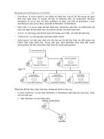
Figure 4-1 shows the memory space of S3C44B0X (after reset). The special function registers are located at
4M-memory space from 0x01C00000 to 0x20000000. The start addresses and size of Bank0-Bank5 are fixed.
The start address of Bank 6 is fixed, but its size is changeable. Bank 7 memory can be configured as 2/4/8/16/32
Mb and its start address and size are not fixed. The detailed relationship between the memory address and
memory size of Bank 6 and Bank 7 memory is shown in Table 4-1.
Embedded Systems Development and Labs; The English Edition
134
Note: SROM means ROM or SRAM
Figure 4-1 S3C44B0X Memory Space (after reset)
Table 4-1 Bank6/Bank7 Addresses
1) Big/Small Endian Selection
While nRESET is L, the ENDIAN pin defines which endian mode should be selected. If the ENDIAN pin is
connected to Vss with a pull-down resistor, the little endian mode is selected. If the pin is connected to Vdd with
a pull-up resistor, the big endian mode is selected. This is shown in Table 4-2.
2) Bank0 Bus Width
The data bus width of BANK0 (nGCS0) should be configured as one of 8-bit, 16-bit and 32-bit. Because the
BANK0 is the booting ROM bank (mapped to 0x0000_0000), the bus width of BANK0 should be determined
before the first ROM access, which will be determined by the logic level of OM[1:0] at Reset.
Embedded Systems Development and Labs; The English Edition
135
Table 4-2 Big/Samll Endian
Table 4-3 Bus Width Selections
3) Memory Controller Specific Registers
Memory Controller Specific Registers includes Bus Width & Wait Control Register (BWSCON), Bank Control
Register (BANKCONn: nGCS0-nGCS5), Refresh Control Register, Banksize Register, SDRAM Mode
Register Set Register (MRSR) shown in Table 4-4 to Table 4-8.
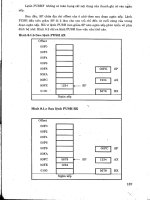
The format of Bus Width & Wait Control Register (BWSCON) is shown in Figure 4-2.
Table 4-4 Bus Width & Wait Control Register (BWSCON)
Embedded Systems Development and Labs; The English Edition
136
Figure 4-2 BWSCON Register Format
Table 4-5 Bank Control Register (BANKCONn: nGCS0-nGCS5)
Table 4-6 Refresh Control Register
Embedded Systems Development and Labs; The English Edition
137
Table 4-7 Banksize Register
Table 4-8 SDRAM Mode Register Set Register (MRSR)
For the detailed definition of the above registers, please refer to S3C44B0X specification.
The following is an example of the 14 memory control registers settings:
ldr r0, =SMRDATA /* loads r0 with the address SMRDATA */
ldmia r0, {r1-r13} /* loads registers r1 to r13 with the consecutive words stored at SMRDATA */
ldr r0, =0x01c80000 ; BWSCON Address
stmia r0, {r1-r13}
SMRDATA DATA
DCD 0x22221210 ; BWSCON
DCD 0x00000600 ; GCS0
DCD 0x00000700 ; GCS1
DCD 0x00000700 ; GCS2
DCD 0x00000700 ; GCS3
DCD 0x00000700 ; GCS4
DCD 0x00000700 ; GCS5
DCD 0x0001002a ; GCS6, EDO DRAM(Trcd=3, Tcas=2, Tcp=1, CAN=10bit)
DCD 0x0001002a ; GCS7, EDO DRAM
DCD 0x00960000 + 953 ; Refresh(REFEN=1, TREFMD=0, Trp=3, Trc=5, Tchr=3)
DCD 0x0 ; Bank Size, 32MB/32MB
DCD 0x20 ; MRSR 6(CL=2)
DCD 0x20 ; MRSR 7(CL=2)
The 13 control registers are located at consequent memory addresses starting from 0x01C80000. As a result, the
instruction “stmia r0, {r1-r13}” writes the configuration data to the corresponding registers. The Embest
S3CEV40 memory (SROM/DRAM/SDRAM) address pin connection are shown in Table 4-9.
4) Memory (SROM/DRAM/SDRAM) Address Pin Connections
The Embest S3CEV40 chips select signals usage is shown in Table 4-10.
Embedded Systems Development and Labs; The English Edition
138
Table 4-9 Memory (SROM/DRAM/SDRAM) Address Pin Connections
Table 4-10 chips select signal usage
Chip Select signal (CS) Chips or External Modules
NGCS0 FLASH
NGCS6/NSCS0 SDRAM
NGCS1 A20 A19 A18
0 0 0 CS1 USB
0 0 1 CS2 Solid-state Hard Disc (Nand Flash)
0 1 0 CS3
IDE
0 1 1 CS4
1 0 0 CS5
1 0 1 CS6 8-SEG
1 1 0 CS7 ETHERNET
1 1 1 CS8 LCD
5) Peripherals accesses address settings
The peripherals accesses address settings is shown in Table 4-11.
Table 4-11 Peripherals accesses address settings
Peripheral CS CS register Address space
FLASH NGCS0 BANKCON0 0X0000_0000~0X01BF_FFFF
SDRAM NGCS6 BANKCON6 0X0C00_0000~0X0DF_FFFF
USB CS1 BANKCON1 0X0200_0000~0X0203_FFFF
Embedded Systems Development and Labs; The English Edition
139
Solid-state Hard Disc CS2 BANKCON1 0X0204_0000~0X0207_FFFF
IDE(IOR/W) CS3 BANKCON1 0X0208_0000~0X020B_FFFF
IDE(KEY) CS4 BANKCON1 0X020C_0000~0X020F_FFFF
IDE(PDIAG) CS5 BANKCON1 0X0210_0000~0X0213_FFFF
8-SEG CS6 BANKCON1 0X0214_0000~0X0217_FFFF
ETHERNET CS7 BANKCON1 0X0218_0000~0X021B_FFFF
LCD CS8 BANKCON1 0X021C_0000~0X021F_FFFF
NO USE NGCS2 BANKCON2 0X0400_0000~0X05FF_FFFF
KEYBOARD NGCS3 BANKCON3 0X0600_0000~0X07FF_FFFF
NO USE NGCS4 BANKCON4 0X0800_0000~0X09FF_FFFF
NO USE NGCS5 BANKCON5 0X0A00_0000~0X0BFF_FFFF
NO USE NGCS7 BANKCON7 0X0E00_0000~0X1FFF_FFFF
2. Circuit Design
The memory system of the development board includes a 1M×16bit Flash (SST39VF160) and a 4M×16bit
SDRAM (HY57V65160B). As shown in Figure 4-3, the Flash chip is enabled by the nGCS0 signal. The Flash
address space is from 0x00000000 ~ 0x00200000. As a result, the processor’s address bits A0-A19 are used.
Figure 4-4 presents the SDRAM connection diagram. The SDRAM memory is divided into 4 equal memory
banks of 1Mx16 bits. The BANK’s address is determined by BA1, BA0 pins (00 corresponds to BANK0, 01
corresponds to BANK1, 10 corresponds to BANK2, 11 corresponds to BANK3). Each bank uses the row
address pulse to select RAS and the column address pulse to select CAS to carry on the addressing. This
development board also has Jumpers that allow for memory update to 4×2M×16bit. For 8M SDRAM, R1 and
R3 are 0 ohms and R2 and R4 are empty. Namely, BA0, BA1 are connected separately to A21 and A22; both
row and column address wire width are A1~A11. As a result, the address space is 4×2
10
×2
10
, (from 0x0C000000
~ 0x0C3FFFFF). For 16M SDRAM, R2 and R4 are 0 ohms and R1 and R3 are empty. Namely, BA0, BA1 are
connected to A22, A23, respectively; both row and column address wire width are A1~A12. The address space
is 4×2
11
×2
11
, from 0x0C000000 ~ 0x0C7FFFFF. The SDRAM chip is selected by MCU through the chip select
signal nSCS0 and its address space is from 0x0C000000 ~ 0x0C8000000.
Embedded Systems Development and Labs; The English Edition
140
Figure 4-3 Connection Circuit
Figure 3-4 Connection Circuit
4.1.5 Operation Steps
1) Prepare the Lab environment. Connect the Embest Emulator to the target board. Connect the target board
UART0 to the PC serial port through the serial cable that comes with the Embest development system.
2) Run the PC Hyper Terminal. Click Start >> All Programs >> Accessories >> Communication >> Hyper
Terminal. In the Hyper Terminal Window click the disconnect icon and then configure the COM1 port to the
following properties: 115200 bits per second, 8 data bits, none parity, 1 stop bits, none flow control.
3) Connect the Embest Emulator to the target board. Open the Memory_Test.ews project file in the
Memory_test sub directory in the sample directory. After compiling and linking, connect to the target board and
download the program.
NOTE: If the program does not execute properly in the workspace window click on the common directory >>
click the file 44init.s >> click delete. Open the 44init.s file that is located in
the …\Samsung\S3CEV40\ALL_Test\asm directory and attach this file to the common directory of the project.
Embedded Systems Development and Labs; The English Edition
141
Have the 44init.s window active and compile the file by clicking on the Build >> Compile 44init.s. After this
build the project and reconnect and download the code to the board. Make sure that the \common\ev40boot.cs
file is present in the debug window of the project settings.
4) Open Memory1 window, key in the address 0x0C010000. Open Memory2 window, key in the address
0x0C010200.
5) Open Rwrams.s, set a break point at the line “LDR r2, =0x0C010000”. Open Rwarmc.c, set a break point at
the line “*ptr=0xAA55AA55;”.
6) Execute the program. The program will stop at the line “LDR r2, =0x0C010000”. Watch the date content in
the Memory1 window. Single step execute the program and watch the changes in Memory 1 window. According
to the program, master the method of visiting memory using assembly language.
7) When the program stops at the line “*ptr=0xAA55AA55;”, watch the content in the Memory2 window.
Single step execute the program and watch the changes in Memory2 window. According to the program, master
the method of visiting memory using C language.
8) After understanding and mastering the lab, finish the Lab exercises.
4.4.6 Sample Programs
44binit.s, 44blib.c: these source files can be found in the …\Samsung\S3CEV40\Common directory.
RWrams.s source code:
//////////// RAM read/write using assembly language
sRWramtest:
LDR r2,=RWBase
LDR r3,=0x55AA55AA
STR r3,[r2]
LDR r3,[r2] /*// Read by Word.*/
ADD r3,r3,#1
STR r3,[r2] /*// Write by Word.*/
LDR r2,=RWBase
LDRH r3,[r2] /*// Read by half Word.*/
ADD r3,r3,#1
STRH r3,[r2],#2 /*// Write by half Word.*/
STRH r3,[r2]
LDR r2,=RWBase
LDRB r3,[r2] /*// Read by half Byte.*/
LDRB r3,=0xDD
STRB r3,[r2],#1 /*// Write by half Byte.*/
LDRB r3,=0xBB
STRB r3,[r2],#1
Embedded Systems Development and Labs; The English Edition
142
LDRB r3,=0x22
STRB r3,[r2],#1
LDRB r3,=0x11
STRB r3,[r2]
mov pc,lr /* The LR register may be not valid for the mode changes. */
RWramc.c source code:
//////////// RAM read/write using C language
#define RWram (*(unsigned long *)0x0c010200)
void cRWramtest(void)
{
unsigned long * ptr = 0x0c010200;//RWram;
unsigned short * ptrh = 0x0c010200;//RWram;
unsigned char * ptrb = 0x0c010200;//RWram;
char i;
unsigned char tmpb;
unsigned short tmph;
unsigned long tmpw;
*ptr = 0xAA55AA55;
tmpw = *ptr; /*// Read by Word.*/
*ptr = tmpw+1; /*// Write by Word.*/
tmph = *ptrh; /*// Read by half Word.*/
*ptrh = tmph+1; /*// Write by half Word.*/
tmpb = *ptrb; /*// Read by half Byte.*/
*ptrb = tmpb+1; /*// Write by half Byte.*/
}
main.c source code:
#define RWNum 100
#define RWBase 0x0c030000
/* function declare */
void Test_MEM(void);
void main(void);