Tài liệu sửa chữa hộp số tự động A650E
Bạn đang xem bản rút gọn của tài liệu. Xem và tải ngay bản đầy đủ của tài liệu tại đây (2.18 MB, 143 trang )
IN049-26
-INTRODUCTION TERMS
IN-5
5Author: Date:
A650E AT (RM780U)
TERMS
ABBREVIATIONS USED IN THIS MANUAL
Abbreviations Meaning
A/T Automatic Transmission
ATF Automatic Transmission Fluid
B
0
Overdrive Brake
B
1
3rd Coast Brake
B
2
3rd Brake
B
3
2nd Brake
B
4
1st & Reverse Brake
C
0
Overdrive Direct Clutch
C
1
Forward Clutch
C
2
Direct Clutch
D Disc
F Flange
F
0
Overdrive One-way Clutch
F
1
No. 1 One-way Clutch
F
2
No. 2 One-way Clutch
FIPG Formed in Place Gasket
MP Multipurose
O/D Overdrive
P Plate
S1 Shift Solenoid Valve No. 1
S2 Shift Solenoid Valve No. 2
S3 Shift Solenoid Valve No. 3
S4 Shift Solenoid Valve No. 4
SSM Special Service Materials
SST Special Service Tools
w/ with
w/o without
AT04F-02
D01296
Pin
E-Ring
Spring
Retainer
Spring
O-Ring
Piston Rod
Oil Seal Ring
Piston
E-Ring
Cover
Snap Ring
D
Non-reusable part
D
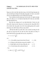
3rd Coast Brake Band
-AUTOMATIC TRANSMISSION THIRD COAST BRAKE
AT-45
68Author: Date:
A650E AT (RM780U)
THIRD COAST BRAKE
COMPONENTS
AT04N-02
D09433
Snap Ring
Flange
Flange
Snap Ring
Piston Return Spring
O-Ring
O/D Brake Piston
O/D Support
Thrust Washer
Oil Seal
D
D
Non-reusable part
Disc
Plate
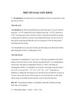
-AUTOMATIC TRANSMISSION OVERDRIVE BRAKE
AT-49
72Author: Date:
A650E AT (RM780U)
OVERDRIVE BRAKE
COMPONENTS
AT05H-02
D01250
Shift Solenoid Valve SLU
Shift Solenoid Valve SLN
Shift Solenoid Valve No. 3
Shift Solenoid Valve No. 1
Shift Solenoid
Valve No. 2
Shift Solenoid
Valve No. 4
Spring Plate
Detent
Spring
Manual Valve
Pressure Relief
Valve Spring Seat
6.4 (65, 56 in.·lbf)
No. 1 Lock Plate
No. 2 Lock Plate
Spring
Ball
N·m (kgf·cm, ft·lbf)
: Specified torque
Shift Solenoid Valve SLT
D
D
D
D
D
D
O-Ring
Non-reusable partD
Oil Guide Plate
9.8 (100, 7)
9.8 (100, 7)
9.8 (100, 7)
9.8 (100, 7)
6.4 (65, 56 in.·lbf)
9.8 (100, 7)
9.8 (100, 7)
-AUTOMATIC TRANSMISSION VALVE BODY
AT-103
126Author: Date:
A650E AT (RM780U)
VALVE BODY
COMPONENTS
D01478
Lower No. 2 Valve Body
Strainer
Plate
Orifice Control
Thermal Valve
Lower No. 1 Valve Body
Check Valve
Upper Valve Body
Spring
6.4 (65, 56 in.·lbf)
Strainer
Strainer
6.4 (65, 56 in.·lbf)
N·m (kgf·cm, ft·lbf) : Specified torque
Oil Cooler
Return Pipe
Check Ball
X28
X11
6.4 (65, 56 in.·lbf)
6.4 (65, 56 in.·lbf)
Plate
AT-104
-AUTOMATIC TRANSMISSION VALVE BODY
127Author: Date:
A650E AT (RM780U)
AT05K-01
D01258
Retainer
Plug
C-1 Orifice Control
Valve
Plug
Retainer
Plug
C-1 Accumulator Valve
Solenoid Modulator Valve
Check Valve
Retainer
Retainer
Retainer
Plug
Lock-up Relay Valve
C-0 Exhaust Valve
4-5 Shift Valve
Coast Brake Control Valve
Retainer
Plunger
Sleeve
Plug
Retainer
Retainer
Plug
Plunger
Sleeve
Retainer
Secondary Regulator Valve
Retainer
2-3 Shift Valve
Strainer
Strainer
Plug
Retainer
Sleeve
Plunger
B-3 Control Valve
Plate
-AUTOMATIC TRANSMISSION UPPER VALVE BODY
AT-113
136Author: Date:
A650E AT (RM780U)
COMPONENTS
AT05M-01
D01256
Check Valve
3-4 Shift Valve
Plug
Retainer
1-2 Shift Valve
Retainer
Plug
Retainer
B-2 Release Control Valve
Primary Regulator Valve
Plunger
Sleeve
Retainer
Cut Back Valve
Retainer
Plug
Retainer
Accumulator Control Valve
Plunger
Sleeve
Retainer
Solenoid Relay Valve
Retainer
Plug
Retainer
C-0 Control Relay Valve
Lock-up Control Valve
Sleeve
Retainer
Plunger
Plug
Strainer
-AUTOMATIC TRANSMISSION LOWER NO.1 VALVE BODY
AT-117
140Author: Date:
A650E AT (RM780U)
COMPONENTS
AT05O-01
D01257
Retainer
Plug
Spring
Reverse Control Valve
AT-120
-AUTOMATIC TRANSMISSION LOWER NO.2 VALVE BODY
143Author: Date:
A650E AT (RM780U)
COMPONENTS
AT05Q-02
D09414
Adjusting Bolt
Park/Neutral
Position Switch
Transmission
Wire
Transmission
Case
Union
Extension Housing
Vehicle Speed Sensor
Rotor
D
Transmission
Housing
Oil Seal
16 (160, 12)
5.4 (55, 48 in.·lbf)
57 (580, 42)
Parking Lock
Pawl Bracket
Parking Lock Pawl
Parking Lock Pawl Shaft
C
2
Accumulator Piston
B
0
Accumulator Piston
Valve Body
Spring
Check Ball Body
9.8 (100, 7)
Oil Strainer
Magnet
Oil Pan
D
Drain Plug
20 (205,15)
N·m (kgf·cm, ft·lbf)
Non-reusable part
: Specified torque
D
D
6.9 (70, 61 in.·lbf)
7.4 (75, 65 in.·lbf)
Manual Valve Lever Shaft
Parking Lock Rod
Manual Valve Lever
Spacer
5.4 (55, 48 in.·lbf)
X4
29 (300, 22)
D
D
X20
X18
34 (345, 25)
D O-Ring
B
2
Accumulator Piston
D
D
D
D
Spring
C
0
Accumulator Piston
Spring Pin
D
13 (130, 9)
5.4 (55, 48 in.·lbf)
O/D Direct Clutch
Speed Sensor
D
D
Gasket
Oil Seal
D
D
E-Ring
Stopper
Plate
7.4 (75, 65 in.·lbf)
Elbow
29 (300, 22)
Vehicle Speed
Sensor
Lock Washer
7.4 (75, 65 in.·lbf)
D
Spring
Snap Ring
D
9.8 (100, 7)
Breather Hose
Control Shaft Lever
Key
D
D
D Gasket
5.4 (55, 48 in.·lbf)
34 (345, 25)
X6
D
-AUTOMATIC TRANSMISSION COMPONENT PARTS
AT-3
26A uthor: Date:
A650E AT (RM780U)
COMPONENT PARTS
COMPONENTS
D09454
Oil Pump
O-RingD
Race
Assembled
Bearing & Race
O/D Planetary Gear Unit with
O/D Direct Clutch
O/D Brake Pack
Bearing
Race
Race
O/D Support
Direct Clutch
Assembled
Bearing & Race
Thrust Washer
21 (215, 16)
O/D Planetary
Ring Gear
Thrust Washer
Forward Clutch
3rd Coast
Brake Band
Bearing
E-Ring
Pin
Assembled
Bearing & Race
Race
Forward Clutch
Hub
Race
2nd Brake Pack
Front Planetary Gear
Front & Center
Planetary Sun Gear
Rear Planetary
Ring Gear
3rd Coast Brake
Piston
3rd Coast
Brake Cover
Brake Drum
Gasket
D
Output Shaft
with Center & Rear
Planetary Gear
No. 2 One-way
Clutch
Spring
Snap Ring
Washer
Thrust Washer
Assembled
Bearing & Race
Race
N·m (kgf·cm, ft·lbf)
Non-reusable part
D
: Specified torque
X7
No. 1 One-way
Clutch
Multiple Disc
Brake
Snap Ring
Sun Gear
Input Drum
Thrust
Washer
Snap Ring
O-Ring
D
Spring
Snap Ring
Snap Ring
Retainer
Bearing
Spring
Assembled
Bearing & Race
25 (260, 19)
AT-4
-AUTOMATIC TRANSMISSION COMPONENT PARTS
27A uthor: Date:
A650E AT (RM780U)
AT04B-02
D01280
Oil Pump Body
Oil Pump Drive Gear
Stator Shaft
Oil Seal Ring
Oil Pump Driven Gear
Oil Seal
N·m (kgf·cm, ft·lbf)
Non-reusable part
: Specified torque
X13
10 (100, 7)
O-Ring
AT-40
-AUTOMATIC TRANSMISSION OIL PUMP
63Author: Date:
A650E AT (RM780U)
OIL PUMP
COMPONENTS
AT04J-02
D01414
O/D Direct Clutch Drum
O/D Direct Clutch Piston
O/D Planetary Gear
O-Ring
Snap Ring
Plate
Disc
Flange
Snap Ring
D
Piston Return Spring
Snap Ring
Snap Ring
Retaining Plate
O/D One-way
Clutch
One-way Clutch
Outer Race
Bearing
O/D Planetary
Ring Gear
Race
Thrust Washer
One-way Clutch
Inner Race
Ring Gear Flange
D
Non-reusable part
Plate
-AUTOMATIC TRANSMISSION OVERDRIVE DIRECT CLUTCH
AT-55
78Author: Date:
A650E AT (RM780U)
OVERDRIVE DIRECT CLUTCH
COMPONENTS
AT04R-02
D09441
Snap Ring
Piston Return Spring
D O-Ring
Disc
Plate
Flange
Snap Ring
D Non-reusable part
Direct Clutch
Direct Clutch Piston
Cushion Plate
AT-66
-AUTOMATIC TRANSMISSION DIRECT CLUTCH
89A uthor: Date:
A650E AT (RM780U)
DIRECT CLUTCH
COMPONENTS
AT04V-02
D09444
Oil Seal Ring
Forward Clutch
Forward Clutch Piston
Return Spring
Snap Ring
Bearing
O-Ring
Disc
Flange
Snap Ring
D
D
Non-reusable part
Plate
Cushion Plate
AT-72
-AUTOMATIC TRANSMISSION FORWARD CLUTCH
95Author: Date:
A650E AT (RM780U)
FORWARD CLUTCH
COMPONENTS
AT04Z-02
D09447
No. 1 One-way Clutch
Flange
Snap Ring
Plate
Disc
Piston Return Spring
Retainer
3rd Brake Piston
D O-Ring
Brake Drum
2nd Brake Piston
Washer
Front Planetary Gear
Front & Center Planetary
Sun Gear
D Non-reusable part
Snap Ring
D O-Ring
D O-Ring
Washer
AT-78
-AUTOMATIC TRANSMISSION MULTIPLE DISC BRAKE
101Author: Date:
A650E AT (RM780U)
MULTIPLE DISC BRAKE
COMPONENTS
AT053-01
D01473
Front Planetary
Ring Gear
Snap Ring
Center Planetary Gear
Center Planetary
Ring Gear
Bearing
Race
Intermediate Shaft
Output Shaft with
Rear Planetary Gear
Snap Ring
-AUTOMATIC TRANSMISSION CENTER PLANETARY GEAR
AT-85
108Author: Date:
A650E AT (RM780U)
CENTER PLANETARY GEAR
COMPONENTS
AT057-01
D01475
Output Shaft with
Rear Planetary Gear
Rear Planetary
Ring Gear
Rear Planetary
Ring Gear Flange
Snap Ring
Rear Planetary
Sun Gear
-AUTOMATIC TRANSMISSION REAR PLANETARY GEAR
AT-89
112Author: Date:
A650E AT (RM780U)
REAR PLANETARY GEAR
COMPONENTS
AT05B-02
D09451
Snap Ring
Flange
Snap Ring
Piston Return Spring
No. 2 Brake Piston
Reaction Sleeve
No. 1 Brake Piston
D O-Ring
D Non-reusable part
Plate
Disc
-AUTOMATIC TRANSMISSION FIRST AND REVERSE BRAKE
AT-93
116Author: Date:
A650E AT (RM780U)
FIRST AND REVERSE BRAKE
COMPONENTS
AT0Y1-01
D09426
Non-reusable partD
D Oil Seal
Dust Deflector
Extension Housing
D
-AUTOMATIC TRANSMISSION EXTENSION HOUSING
AT-99
122Author: Date:
A650E AT (RM780U)
EXTENSION HOUSING
COMPONENTS
AT04G-01
D01297
D01298
D01299
Piston
Spring
Retainer
Piston Rod
AT-46
-AUTOMATIC TRANSMISSION THIRD COAST BRAKE
69Author: Date:
A650E AT (RM780U)
DISASSEMBLY
1. REMOVE 3RD COAST BRAKE PISTON OIL SEAL
RING
2. REMOVE 3RD COAST BRAKE PISTON ROD
(a) Firmly hold down the piston, then compress the compres-
sion spring.
(b) Remove the E-ring.
(c) Remove the compression spring, retainer and piston rod.
AT04O-02
D01332
D01333
D01334
D09434
SST
D01432
AT-50
-AUTOMATIC TRANSMISSION OVERDRIVE BRAKE
73Author: Date:
A650E AT (RM780U)
DISASSEMBLY
1. CHECK PISTON OPERATION OF O/D BRAKE
(a) Place the O/D support assembly onto the direct clutch as-
sembly.
(b) Apply compressed air (392 kPa, 4 kgf/cm
2
, 57 psi) into the
oil passage and be sure that the O/D brake piston moves
smoothly.
2. REMOVE CLUTCH DRUM THRUST WASHER FROM
O/D SUPPORT
3. REMOVE PISTON RETURN SPRING
(a) Place SST on the spring retainer, and compress the re-
turn spring with a press.
SST 09387-00100
(b) Remove the snap ring with a screwdriver.
(c) Remove the piston return spring.
4. REMOVE O/D BRAKE PISTON
(a) Place the O/D support onto the direct clutch assembly.
(b) Hold the O/D brake piston so it does not slant, and apply
compressed air (392 kPa, 4 kgf/cm
2
, 57 psi) into the pas-
sage to remove the O/D brake piston.
(c) Remove the O/D brake piston.
D01336
O-Ring
O-Ring
D01337
-AUTOMATIC TRANSMISSION OVERDRIVE BRAKE
AT-51
74Author: Date:
A650E AT (RM780U)
(d) Remove the 2 O-rings.
5. REMOVE 2 OIL SEAL RINGS
AT05I-02
D01249
D01248
Manual Valve
D01247
(a)
(b)
(c)
(d)
(e)
(g)
(h)
D01251
Oil Cooler
Return Pipe
Clamp
-AUTOMATIC TRANSMISSION VALVE BODY
AT-105
128Author: Date:
A650E AT (RM780U)
DISASSEMBLY
1. REMOVE DETENT SPRING AND SPRING PLATE
Remove the bolt, detent spring and spring plate.
2. REMOVE MANUAL VALVE
3. REMOVE 7 SOLENOIDS
(a) Remove the bolt and shift solenoid valve No. 1.
(b) Remove the bolt and shift solenoid valve No. 3.
(c) Remove the bolt and shift solenoid valve No. 2.
(d) Remove the bolt and shift solenoid valve No. 4.
(e) Remove the bolt, No. 2 lock plate and shift solenoid valve
SLN.
(f) Remove the oil guide plate.
(g) Remove the bolt, No. 1 lock plate and shift solenoid valve
SLU, SLT.
(h) Remove the bolt, pressure relief valve spring seat, spring
and ball.
(i) Remove the 6 O-rings from shift solenoid valve No. 1, No.
2, No. 3 and No. 4.
4. REMOVE LOWER NO. 2 VALVE BODY
(a) Remove the 12 bolts. 2 of them are attached to the oil
cooler return pipe and clamp. So remove them all togeth-
er.
D01252
Plate
Lower No. 2
Valve Body
D01261
Check Ball
Orifice Control
Thermal Valve
D01253
D01254
D01259
Plate
AT-106
-AUTOMATIC TRANSMISSION VALVE BODY
129Author: Date:
A650E AT (RM780U)
(b) Remove the lower No. 2 valve body.
(c) Remove the plate.
(d) Remove the strainer.
(e) Remove the orifice control thermal valve and check ball.
5. REMOVE UPPER VALVE BODY
(a) Turn over assembly and remove the 30 bolts.
(b) Remove the plate from the upper valve body.
(c) Remove the upper valve body with the plate.
(d) Remove the check valve and spring.
(e) Turn over upper valve body, remove the 2 screws and
plate.
(f) Remove the 2 strainers.
AT0XZ-01
D09415
D09457
D01108
Union
Elbow
D01111
D01112
-AUTOMATIC TRANSMISSION COMPONENT PARTS
AT-5
28A uthor: Date:
A650E AT (RM780U)
DISASSEMBLY
1. REMOVE CONTROL SHAFT LEVER
Remove the nut, washer and control shaft lever.
2. REMOVE PARK/NEUTRAL POSITION SWITCH
(a) Using a screwdriver, unstake the lock washer.
(b) Remove the lock washer, nut and bolt.
(c) Remove the bolt and park/neutral position switch.
3. REMOVE UNION AND ELBOW
(a) Remove the union and elbow.
(b) Remove the 2 O-rings from the union and elbow.
4. REMOVE SPEED SENSOR
(a) Remove the 2 bolts and 2 speed sensors.
(b) Remove the O-ring from each one.
5. REMOVE TRANSMISSION HOUSING
(a) Remove the bolt and breather hose.