Điều khiển nhiệt độ KP2000 INE 809a
Bạn đang xem bản rút gọn của tài liệu. Xem và tải ngay bản đầy đủ của tài liệu tại đây (1.91 MB, 144 trang )
INST.No.INE-809A
Digital Program Controller
KP2000
[General]
1. Introduction 1 -
2. For safe use of the product 3 -
2.1 Prerequisites for use - 3 -
2-2. Symbol mark - 3 -
2-3. Important - 4 -
3. Model code list 5 -
4. Mounting and wiring 6 -
4-1. External dimensions - 6 -
4-2. Mounting - 7 -
4-3. Wiring - 9 -
5. Name of various parts 20 -
5-1. Entire overview - 20 -
5-2. Overview of the front panel 20 -
5-3. Details of the front panel 21 -
6. Operation screen 23 -
6-1.Output display screen - 23 -
6-2 Time display screen - 24 -
6-3 Program pattern overall display screen - 24 -
6-4.
Output display screen of output 2 specifications - 25 -
6-5. Operation screen and setting screen - 26 -
7. Setting screen 27 -
7-1. Basics of setting - 27 -
7-2. Mode 0 [Setting of parameters that are being
executed] - 29 -
7-3. Mode 1 [Setting related to operation status] - 31 -
7-4. Mode 2 [Setting related to program pattern] - 34 -
7-5. Mode 3 [Setting relate to PID and alarm] - 38 -
7-6. Mode 4 [Setting related to output] 43 -
7-7. Mode 5 [Setting related to input] 47 -
7-8. Mode 6 [Setting related to time event] - 50 -
7-9. Mode 7
[Setting related to transmission output] 51 -
7-10. Mode 8
[Setting related to communications] - 53 -
7-11.Mode 11 [Setting related to system] - 57 -
7-12. Mode 12 [Setting related to customer scale
correction] - 60 -
7-13. Initializing the setup parameter - 62 -
7-14. Precautions while setting 63 -
7-15. Error message - 64 -
8. Initial settings 67 -
9. Operation 68 -
9-1. Confirmations before operation - 68 -
9-2. Program operation and run operation - 68 -
9-3. Trial operation - 71 -
9-4. Constant value operation - 72 -
9-5. Automatic output operation and manual output
operation - 73 -
9-6.Precautions during operation - 74 -
10. Detailed explanation of main functions - 76 -
10-1 Measurement range - 76 -
10-2 .Linear scale - 77 -
10-3. Alarm mode - 78 -
10-4. Auto tuning - 85 -
10-5. PID control - 86 -
10-6. Automatic PID switching system - 87 -
10-7. Actuator adjustment of ON-OFF servo type- 88 -
10-8. Output 2 - 89 -
10-9. Transmission signal output - 90 -
10-10. External signal input - 91 -
10-11. External signal output - 95 -
10-12. Timer slave synchronous operation - 97 -
10-13. Communication interface - 99 -
10-14. Customer scale correction - 100 -
11. Various type of option 106 -
12. Engineering port 118 -
13. Trouble shooting 119 -
14. Checking and maintenance 121 -
14-1. Checking 121 -
14-2. Life component - 121 -
14-3. Disposal 121 -
15. Explanation of terms 122 -
16. Accessories 126 -
16-1. Front protective cover 126 -
16-2. Contact protection element - 126 -
17. Specifications 127 -
18. Parameter list 131 -
19. Parameter directory list 137 -
20. Engineering unit sticker 139 -
Table of Contents
- 1 -
1. Introduction
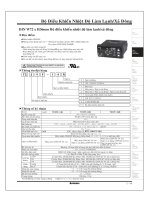
Thank you for purchasing Digital Program Controller 'KP 2000 series'.
KP 2000 series is Digital Program Controller with indicating accuracy of ±0.1%, control cycle of approximately
0.1 seconds and front size of 96X96mm.
Universal input and storing up to 30 types of program patterns etc. are the various functionalities that are
provided as standard provisions. Besides a digital indicator with large easy to view LED display, various settings
have an interactive system with high resolution dot matrix LCD display and handling is also easy with precise
control. Besides a digital indicator with large easy to view LED display, various settings have an interactive system
with high resolution dot matrix LCD display and handling is also easy with precise control.
Understand the controller properly and read this instruction manual beforehand in order to avoid any trouble.
This is a 'General' instruction manual. For specification regarding communications, read 'Communication'
instruction manual along with this manual.
- For the persons doing instrumentation, installation and sales -
Be sure to handover this instruction manual to the persons using the controller.
- For the users of the controller -
Preserve this instruction manual carefully until you scrap the controller.
Write down and keep the contents of setting.
Request
1. You should not copy or forward fully or partially this document without prior notice.
2. The contents of this document may be changed without notice.
3. We have taken enough care regarding the contents of this document however if at all you notice a
mistake, contact our nearest office.
4. Please understand that regarding the result of the operation, whatever is the result the company will
not be responsible.
Notices
- 2 -
■Before use
After opening the pack, confirm the following before using the product. Although it is rare but if you notice
anything wrong, contact your dealer or our nearest office.
1. Confirm the exterior
Confirm that the product is not broken on the outer side.
1. Confirm the model code
Confirm that the model code is that of the model that you want to purchase.
◆Model code label and its location
A label as shown below is pasted on the upper surface of the controller unit.
KP2□□□□□□□-□□□
←Model code
□□□□□□□□□
←Serial number
MADE IN JAPAN
3. Confirm the accessories
The following accessories are attached to the controller, confirm them.
Name Quantity Remarks
Mounting bracket 2 (1 set) For panel mounting
Contact protection element 1
Attached to ON-OFF servo type specifications
only
Instruction manual (General) 1 This document
Instruction manual
(Communications interface)
1
Attached to communications specifications only
(in CD-R)
When accessories are requested separately, sometimes those are also attached.
1. Do not drop the instrument while taking it out of the box.
2. When transporting this instrument, pack the instrument in the box and then put it with cushions in another
box. We recommend keeping the box for transport.
3. When not using the instrument for a while after taking it from the panel, put the instrument in the box and
store at room temperature and in a dust free atmosphere.
Attention
- 3 -
2. For safe use of the product
In order to use the controller safely, read the following precautions and understand them.
2.1 Prerequisites for use
The controller is a general product of component type that is to be used by mounting it in a panel for
instrumentation inside a room. Do not use it in any other condition.
When using, design a fail safe on the final product side and review regularly and use the controller after
confirming the safety of the system. For the wiring, adjustment and operation of the controller contact a
professional having knowledge of instrumentation.
It is necessary that the people actually using this controller read this instruction manual, and have enough
understanding of various precautions and the basic operations of the controller.
2-2. Symbol mark
The following symbol marks are used in the product itself and in this instruction manual hence understand the
meaning of these symbol marks properly.
Symbol mark Meaning
If there is a possibility of death or severe injuries then it explains the
precautions to avoid that possibility.
If there is a possibility of small injuries or a possibility of the controller or its
peripheral devices getting damaged then it explains the precautions to avoid
those possibilities.
It is a symbol for ground terminal. Always connect the ground terminal to
protective grounding.
Warning
Precaution
Perchlorate Material
This instrument uses battery with Perchlorate Material.
Special handling may apply, see
Warning
- 4 -
2-3. Important
Warning
In order to avoid severe accidents always read these contents and
understand them.
1. Confirm the power supply voltage and wiring
Before supplying the power to the instrument, check that the wiring is correct, power supply voltage
matches with the rated voltage and grounding is done.
2. Install over current protection device
The controller does not have a power supply switch. Install an over current protection device (Breaker
etc.) that matches the rating specifications, in the power supply of the controller.
3. Protection of terminal
To prevent electric shock, provide the terminal of the controller with safety measures such that the user
will not directly be able to touch the final product.
4. Installing the safety device
Regarding the use of a device that anticipates a big loss due to failure of the controller and the
peripheral devices, always install a safety device for preventing these losses and implement fail safe
design in the final product. Do not use it in important utilities facilities in which human life, atomic energy,
aviation, space etc, are involved.
5. Do not put your hands inside the controller
Do not put your hand or a tool inside the controller. You may get an injury or an electric shock.
6. Power cut off in case of suspicion
If there is an offensive smell, a strange noise or smoke or if the temperature increases abnormally, it is
very risky hence cut off the power supply immediately and contact the dealer or our nearest office.
7. Prohibiting repairing and remodeling
If repairing or remodeling is necessary, contact the dealer or our nearest office. Only the service
engineers appointed by our company will change the parts, do the repairing and remodeling.
8. Strictly follow the instruction manual
In order to use the controller correctly and safely, follow this instruction manual. Please understand
beforehand that our company will not at all be responsible for any claims for injury, damage, and passive
damage due to wrong use of the product.
- 5 -
3. Model code list
KP2 ④ ⑤ ⑥ ⑦ ⑧ ⑨ ⑩ - ⑫ ⑬ ⑭
④ Input signal ⑨Additional specifications of zone 2*
0 : Universal input 0 : None
4 : 4-wire resistance thermometer J : Transmission signal output, output 2 (General type: 4-20mA)
Ú3
⑤ Control mode (Output 1) K : Transmission signal output, output 2 (General type: 0-1V)
Ú3
1 : ON-OFF pulse type PID L : Transmission signal output, output 2 (General type: 0-10V)
Ú3
2 : ON-OFF servo type PID (Standard specifications) H : Transmitter power supply Ú4
3 : Current output type PID ⑩ Zone 3*
5 : SSR drive pulse type PID 0 : None
6 : Voltage output type PID R : Communication 1 port (RS232C) + 3 external signal inputs
8 : ON-OFF servo type PID (Very little load specifications)
A : Communication 1 port (RS422A) + 1 external signal input
⑥ Control mode (Output 2)* S : Communication 1 port (RS485) + 3 external signal inputs
0 : None B : Communication 2 port (RS232C + RS232C) +
1 external signal input
1 : ON-OFF pulse type PID Ú1 C : Communication 2 port (RS232C + RS422A) +
1 external signal input
3 : Current output type PID
Ú1 D : Communication 2 port (RS232C + RS485)
+ 1 external signal input
5 : SSR drive pulse type PID
Ú1 E : Communication 2 port (RS485 + RS232C)
+ 1 external signal input
6 : Voltage output type PID
Ú1 F : Communication 2 port (RS485 + RS422A)
+ 1 external signal input
⑦ Zone 1* G : Communication 2 port (RS485+RS485) + 1 external signal input
0 : None 9 : Heater snapping wire alarm
Ú2
9 : Heater snapping wire alarm P : External signal input 6 points
P : External signal input 6 points M : External signal input 4 points + Heater snapping wire alarm
Ú2
M :
External signal input 4 points + Heater snapping wire alarm
Ú2
T : External signal output 6 points
T : External signal output 6 points N : External signal output 4 points + Heater snapping wire alarm
Ú2
N :
External signal output 4 points + Heater snapping wire alarm
Ú2 U : External signal input 8 points
⑧ Zone 2* V : External signal input 6 points + Heater snapping wire alarm
(2
0 : None
W : External signal output 8 points
1 :
Transmission signal output (
High performance type
: 4-20mA)
X : External signal output 6 points
+
Heater snapping wire alarm Ú2
2 :
Transmission signal output
(High performance type
:0-1V)
Y : External signal input 3 points + External signal output 5 points
3 :
Transmission signal output (
High performance type
:0-10V)
Z : External signal input 4 points + External signal output 4 points
4 :
Transmission signal output (
High performance type
: Others)
⑫ Case color
J : Transmission signal output (General type:4-20mA) G : Gray
K : Transmission signal output (General type:0-1V) B : Black
L : Transmission signal output (General type:0-10V) ⑬ IP54 panel sealing specifications and terminal cover*
9 : Heater snapping wire alarm Ú2 0 : None
P : External signal input 6 points 1 : Terminal cover exists
M :
External signal input 4 points + Heater snapping wire alarm
Ú2 2 : IP54 panel sealing specifications + No terminal cover
T : External signal output 6 points 3 : IN54 panel sealing specifications + Terminal cover
N :
External signal output 4 points + Heater snapping wire alarm
Ú2 ⑭Power supply voltage
A : 100-240V(AC)
D : 24V(AC/DC)
* Option
Ú1: It can be selected when control mode (output number 1) is 1, 3, 5, or 6.
Ú2: It can be selected when control mode (output number 1) or control mode (output number 2) is 1 or 5 (pulse type).
Heater snapping wire alarm cannot overlap with other zones.
When output 1 and output 2 are both pulse type, alarm is judged output 1 side.
Ú3: It can be selected when zone 2 is 1, 2, 3, or 4.
Ú4: It can be selected when zone 2 is 0, 1, 2, 3, 4, J, K, or L
Note: Common options of zone 1,2,3 are designated form zone 3 ordering [9], [P], [M]
- 6 -
4. Mounting and wiring
4-1. External dimensions
120
7
88×88
115
Unit: mm
147
91×91
Terminal cover
96
96
Mounting bracket
120
7
91×91
115
- 7 -
4-2. Mounting
4-2-1. Panel cutout and mounting method
1.Usual mounting method
① Insert this product in panel cutout.
② Fit in the attached mounting bracket above and below and tighten the screws with the driver and fix it.
When the screws are tightened the torque is '0.6 – 0.8 Nm'.
③ For IP54 panel sealing specifications, confirm that the gasket between product and panels is correct.
Take care because if the gasket drifts or if there is a gap, the mounting is not proper and the water proofing
function does not work.
Panel cut
Unit: mm
2. Closed instrumentation
① Insert this product in panel cutout.
② Fit in the attached mounting bracket above and below and tighten the screws with the driver and fix it.
When the screws are tightened the torque is '0.6 - 0.8 Nm'.
③ At the time of closed instrumentation, even in the product of IP54 panel sealing specifications, as the
gasket functionality between the product and the panel is lost, water proofing functionality does not work.
Unit: mm
N: Number of mounted instruments
Panel cutout for closed instrumentation
120
120
92
+0.8
0
92
+0.8
0
Panel
Mounting
bracket
Controller
96×N-4
+2
0
92
+0.8
0
- 8 -
4-2-2. Installation condition
Precaution
In order to avoid accidents always read and understand these
contents.
1. Environment
① In a room.
② Away from direct sunlight.
③ Away from high temperatures.
④ Where there are no vibrations and shocks.
⑤ Away from liquids (water etc.).
⑥ Away from condensation.
⑦ Under 'Excess voltage category Ⅱ, Pollution level 2' based on EN standards.
2. Atmosphere
① Away from strong noise, static electricity, electric field, magnetic field etc.
② Surrounding temperature within -10 to 50°C (Less than 40°C in case of closed instrumentation),
surrounding humidity within 10-90% RH.
③ Variation in temperature is less.
④ Away from corrosive gas, explosive gas, ignition gas and combustible gas.
⑤ Away from salt, iron and conductive material (Carbon, iron etc.).
⑥ Away from steam, oil and chemicals etc.
⑦ Away from dust etc.
⑧ Away from the surroundings where high temperature is generated.
⑨ Away from places where temperature remains stored.
⑩ Lot of space above the upper part of the product.
⑪ Away from wind.
3. Mounting position
① Installation height is less than 2,000 m above the sea level
② Mounting position is approximately 1.5m (Approximately eye level position of a person).
③ Mounting orientation longitudinal tilting is less than ±10° lateral tilting is less than ±10°.
4. Other
① Do not wipe the controller with an organic solvent (like alcohol).
② To avoid malfunctioning of the controller, do not use cell phones in its vicinity.
③ An obstacle may be created for television and radio sets placed near the controller.
- 9 -
4-3. Wiring
4-3-1. Terminal number and functionality
Depending on the product specifications, there are also places where terminal screw is not provided.
1. Power supply terminal
① General power supply specifications
Terminal
number
⑨
⑩
Ⓝ
⑪
Ⓛ
② 24V power supply specification
Terminal
number
For 24 V DC For 24 V AC
⑨
⑩
Ⓝ
⑪
Ⓛ
100-240V AC
(50/60Hz)
(50/60Hz)
24VAC
24VDC
Alarm terminal
Zone 1
Zone 2
Zone 3
Option terminal
Input terminal
Alarm terminal
Output terminal
Ground terminal and power supply terminal
34
1
2
3
4
5
6
7
8
9
10 11
12
13
14
15
16
17
18
19
20
21
22
23
24
25
26
27
28
29
30
31
32
33
35
36
37
38
39
40
41
42
43
+
-
- 10 -
2. Input terminal
Terminal
number
Thermocouple
Voltage mV
Voltage V
(Range No.35)
(Range No.37)
Current mA
(Range No.36)
Resistance
thermometer
(3-wire type)
Resistance
thermometer
(4-wire type)
①
Ⓐ
②
Ⓐ Ⓐ
③
Ⓑ Ⓑ
④
Ⓑ Ⓑ
⑤
Note) Do the wiring only for the specified terminals.
Note) For current mA, short circuit ③ and ⑤.
3. Output terminal
① ON-OFF pulse type
Terminal
number
Internal circuit
N.C.
Ⓗ
COM.
Ⓒ
Output 1
N.O.
Ⓛ
N.C.
Ⓗ
COM.
Ⓒ
Output 2
N.O.
Ⓛ
② ON-OFF servo type
Terminal
number
Internal circuit
CLOSE
M3
OPEN
M2
COM.
M1
OPEN
R1
COM.
RC
CLOSE
R2
Note) On open loop method (option), terminal number
,
,
are not used.
- 11 -
③ Current output type, SSR drive pulse type, Voltage output type
Terminal
number
Current output
type
SSR drive pulse type
Voltage output
type
Output 1
Output 2
4. Alarm terminal
Terminal
number
Internal circuit
⑥
⑦
⑧
Note) Common (COM) terminal is common in AL1/AL2 and Common (COM) terminal is common in AL3/AL4.
5. Option terminal
① Zone 1
Terminal
number
Heater
snapping
wire alarm
External
signal
input 6
points
External
signal
output 6
points
Heater
snapping
wire alarm
+
External
signal
input 4
points
Heater
snapping
wire alarm
+
External
signal
output 4
points
Communication
RS-232C
+
External signal
input 3 points
*option
Communication
RS-422A
+
External signal
Input 1 point
*option
Communication
RS-485
+
External signal
input 3 points
*option
⑫ CT DI DO CT CT RD RDA SA
⑬ CT DI DO CT CT SD RDB SB
⑭ DI DO DI DO SG SDA SG
⑮ DI DO DI DO DI SDB DI
⑯ DI DO DI DO DI SG DI
⑰ DI DO DI DO DI DI DI
⑱ COM COM COM COM COM COM COM
AL1
AL2
COM
AL3
AL4
COM
- 12 -
② Zone 2
Terminal
number
Heater snapping
wire alarm
External signal
input 6 points
External signal
output 6 points
Heater snapping
wire alarm
+
External signal
input 4 points
Heater snapping
wire alarm
+
External signal
output 4 points
⑲ CT DI DO CT CT
⑳ CT DI DO CT CT
DI DO DI DO
DI DO DI DO
DI DO DI DO
DI DO DI DO
COM COM COM COM
Terminal
number
Transmission
signal output
General type
Transmission
signal output
High-performance
type
Transmission
signal output
Output 2
specifications
Transmitter
power
supply
Transmission
signal output
General type
+
Transmitter
power supply
Transmission
signal output
High-performance
type
+
Transmitter power
supply
⑲
⑳
General
type
Transmission
output
High-
Performance
type
Transmission
output
Transmitter
power
supply
Transmitter
power supply
③ Zone 3
Terminal
number
Communication
RS-232C
+
External signal
input 3 points
Communication
RS-422A
+
External signal
Input 1 point
Communication
RS-485
+
External signal
input 3 points
RD RDA SA
SD RDB SB
SG SDA SG
DI SDB DI
DI SG DI
DI DI DI
COM COM COM
- 13 -
Terminal
number
Communication
RS-232C
(COM1)
+
Communication
RS-232C
(COM2)
+
External signal
Input 1 point
Communication
RS-232C
(COM1)
+
Communication
RS-422A
(COM2)
+
Externalsignal
Input1point
Communication
RS-232C
(COM1)
+
Communication
RS-485
(COM2)
+
Externalsignal
Input1point
Communication
RS-485
(COM1)
+
Communication
RS-232C
(COM2)
+
Externalsignal
Input1point
Communication
RS-485
(COM1)
+
Communication
RS-422A
(COM2)
+
Externalsignal
Input1point
Communication
RS-485
(COM1)
+
Communication
RS-485
(COM2)
+
Externalsignal
Input1point
RD1
RD1 RD1 SA1 SA1 SA1
SD1
SD1 SD1 SB1 SB1 SB1
COM1
SG1
COM1
SG1
COM1
SG1
COM1
SG1
COM1
SG1
COM1
SG1
RD2 RDA2 SA2 RD2 RDA2 SA2
SD2 RDB2 SB2 SD2 RDB2 SB2
COM2
SG2 SDA2
COM2
SG2
COM2
SG2 SDA2
COM2
SG2
COM2
SDB2
COM2
SDB2
DI DI DI DI DI DI
COM COM COM COM COM COM
Note) There is no insulation between communication 2 ports.
Terminal
number
Heater snapping
wire alarm
External signal
input 6 points
External signal
output 6 points
Heater snapping
wire alarm
+
External signal
input 4 points
Heater snapping
wire alarm
+
External signal
output 4 points
CT DI DO CT CT
CT DI DO CT CT
DI DO DI DO
DI DO DI DO
DI DO DI DO
DI DO DI DO
COM COM COM COM
Terminal
number
External signal
input 8 points
External signal
output 8 points
Heater snapping
wire alarm
+
External signal
input 6 points
Heater snapping
wire alarm
+
External signal
output 6 points
External signal
output 5 points
+
External signal
input 3 points
External signal
output 4 points
+
External signal
input 4 points
DI DO CT CT DO DO
DI DO CT CT DO DO
DI DO DI DO DO DO
DI DO DI DO DO DO
DI DO DI DO DO DI
DI DO DI DO DI DI
DI DO DI DO DI DI
DI DO DI DO DI DI
COM COM COM COM
COM COM
- 14 -
4-3-2. Basics of wiring
Precaution
In order to avoid accidents always read and understand these contents.
1. Connecting to the terminal
① For wiring of terminal use crimp style terminal with insulating sleeve. Always use O type terminal to
secure safety of power supply terminal and grounding terminal. For other types of terminals also we
recommend that you use O type terminal.
② When the terminal screws are tightened the torque is '0.6 - 0.8 Nm'. If a torque exceeding this value is
applied, terminal screw panel gets damaged hence take care.
2. Power supply terminal
① In power supply, place the over current protection device and switch that conforms to the ratings of the
controller, within 3m so that they are easily reachable.
② Use a power supply with 600V vinyl insulation electric line (rating more than 1A AC) and an equal or
greater electric line.
③ To avoid malfunctioning use good quality single phase power supply with little voltage change, wave form
distortion and noise. If the noise is loud use noise filter and insert insulation transformer etc.
④ There is a little leakage of current flow in case of rated power supply hence take care. Leaking current is
approximately 1mA.
Warning
To avoid serious accidents always cut off the power supply and then do the
wiring.
O type
Y type
Insulating sleeve
Insulating sleeve
B
Size
A
A
A: 3.7mm or above
B: 7.0mm or above
Within 3 m
Product
Over current
protection device
Switch
Power
supply
- 15 -
3. Input terminal
① Maximum permitted input of input terminal is as follows. Take care of not applying the input that exceeds
these values. If an input that exceeds the range is applied, the product may get out of order or its
performance may deteriorate remarkably or it may malfunction.
・Thermocouple, voltage mV, voltage V : Less than ±20V.
・Resistance thermometer
: Less than 500Ω or Less than ±5V.
・Current mA
: Less than ±30mA or Less than ±7.5V.
② Parallel connection of input is not allowed. Not only measurement error occurs, but also stable control is
not performed and an error occurs in the entire system.
③ For thermocouple, do the wiring up to the input terminal of the product by a thermocouple or compensation
lead wire.
④ To avoid measurement error for resistance thermometer, use cable such that resistance value of each wire
is equal. Take care as burn out is not provided 4-wire resistance thermometer.
⑤ When connecting a protection device like zenner barrier for input protection, sometimes a big
measurement error may occur. Confirm the combination with protection device and maintain the allowable
signal source resistance and allowable wire resistance of the controller.
4. Output terminal
① Use an output terminal within the rating range. If a load that is out of range is connected, product may get
out of order, its performance may show a remarkable deterioration or it may malfunction.
② For relay output terminal of ON OFF pulse type and ON OFF servo type connect the load through buffer
relay. For contact protection of product internal relay and for noise reduction always insert a contact
protection device on the coil side of the buffer relay. In the controller also, a small type of contact protection
device is built-in for internal relay protection. Take care because a small leak current flows through this
contact protection device and load voltage.
Leak current is approximately 2mA when load voltage is 200V AC and it is approximately 1mA when load
voltage is 100V AC.
5. Alarm terminal
① Use the alarm terminal within the rating range. If a load that is out of range is applied, product may get out
of order, its performance may show a remarkable deterioration or it may malfunction.
② For alarm terminal always connect the load through buffer relay. For contact protection of product internal
relay and for noise reduction always insert a contact protection device on the coil side of the buffer relay.
6. Option terminal
① Use the option terminal within the rating range. If a load that is out of range is applied, product may get out
of order, its performance may show a remarkable deterioration or it may malfunction.
Precaution
① If a power supply that is out of range is connected, product may get out
of order, its performance may show a remarkable deterioration or it
may malfunction.
② If an excess current or excess voltage is applied to input output
terminal of the controller, the controller may get out of order, its
performance may show a remarkable deterioration or it may
malfunction.
- 16 -
4-3-3. Example of wiring
1. ON-OFF servo type wiring
ON-OFF servo type is connected with a motor. Refer to the terminal diagram of the motor that uses three
terminals of control relay output and three terminals of feedback input and do the wiring.
35 (Close) M3
36 (Open) M2
37 (Common) M1
38 (Open) R1
39 (Common) RC
40 (Close) R2
[Controller] [Control motor]
In the above diagram, the controller and control motor manufactured by our company are directly connected
however, while actually connecting always insert a buffer relay and then connect. Futhermore, always connect a
contact protection device in control relay output terminal.
The contact protection device attached to the controller is for the motor (For load current 700 mA and above).
When connecting with buffer relay, use a contact protection device for light load. If the attached contact
protection device is used in buffer relay, operation defect occurs due to leak current.
For your reference symbolic name list of motors of various companies is given below.
Symbolic name list of motors of various companies
Chino
Products
Toho Products
Shin Nippon
Keisetsu
Products
Japan Servo
Products
Yamatake
Products
M3 S S T2 1
M2 O O T1 2
M1 C C T3 3
R1 BM B B Y
RC RM R R T
R2 WM W W G
Control relay
output
Feedback
input
P
ower
supply
Z: Contact protection device
×
×
×
×
×
×
×
×
×
×
×
×
Z
Z
M
Feedback
resistance
- 17 -
2. Relay output wiring example
In relay outputs like ON-OFF pulse type, ON-OFF servo type and alarm output, always connect the load
through buffer relay and contact protection device.
[Controller]
Contact protection device is handled in our company also (See 16. Accessories).
When power supply is an AC power supply, and CR compound device, and power supply have direct current,
diode is generally used.
3. Wiring example of external signal input
In the figure on the left approximately
5V and 2mA is applied to the switch.
Take care about the contact point
capacity.
[Controller]
Various external signal inputs (DI) operate by short circuiting specified external signal input terminal and
common (COM) terminal. Operation by switch and relay is a general method however operation by open
collector output signal of peripheral device is also possible.
4. Wiring example of external signal output
The rating range of open collector
signalis less than maximum current
50mA,DC load, maximum voltage
24VDC.
Take care regarding the load
capacity.
[Controller]
Various external signal outputs (DO) are output using open collector signals. If AC power supply is applied or
load other than the rating range is applied, the controller may get out of order or its performance may deteriorate
remarkably or it may malfunction.
Load(
50mA max)
DO
COM
Power
supply
Z: Contact protection device
Buffer relay
~
×
×
Z
Load
DI
DI
DO
COM
+
+
Load(
50mA max)
DC power supply
+-
- 18 -
In open collector signal if the load capacity is less, connect the load via buffer relay while referring to the
following. In order to reduce noise always insert a contact protection device on the coil side of the buffer relay.
5. Wiring example of CT for heater snapping wire alarm
[Controller] [CT]
Heater snapping wire alarm judges the alarm by measuring heater current by using CT which is sold
separately. Connect the electric wire to the two terminals of CT and do the wiring to the specified terminal of the
controller. As for CT, customers can request it as "U-RD Company Ltd, 'CTL-12-S36-8'" directly from UR-D
company.
CT
Heater
CT
~
Load
×
×
Buffer relay
~
Z
Z: Contact protection device
+
DC power supply
+
-
- 19 -
4-3-4. Precautions while wiring
Warning
In order to avoid accidents always read and understand these contents.
1. Wiring is done by professional
Wiring is to be done by a person having actual experience and basic knowledge of instrumentation.
2. Put the terminal cover
In order to ensure safety, after the wiring is done, take measures so as to prevent direct contact with the
terminal of the controller.
Exclusive terminal cover of the controller is available as accessory (Sold separately).
3. Keep away from strong electric circuit and from noise source
In order to prevent adverse effect due to noise, do not place the controller near a device from which noise is
generated (magnet relay, motor, thyristor regulator, inverter etc.). Also avoid passing the wiring of the
controller and that of noise generating devices through the same duct. Always keep the wiring away from
each other. Take the necessary countermeasures against noise.
4. Careful about connecting ground terminal
Good grounding is important for reliability of the instrument. In most cases, it is better that each instrument
is connected at a point. When connected separately, it is easy to get a bad effect due to noise. Check the
connecting route.
5. Keep away from heat generating sources
In order to avoid bad effect due to high temperature, do not install the controller near heat generating
sources. If the controller is kept near any heat generating source, measurement goes wrong and finally the
life of the product is shortened. Take care about the surrounding temperature of the product.
Avoid places where there is wind and sudden temperature change, it also causes an error in measurement.
Take necessary measures to avoid such surrounding environment.
6. Unused terminal
Do not connect anything to the unused terminal. Controller may get out of order.
7. Countermeasures against erroneous output when power is supplied
When power is supplied, sometimes the output related signal may be momentarily output when the
controller is starting normally. Take the necessary countermeasures by using an external circuit.
- 20 -
5. Name of various parts
5-1. Entire overview
5-2. Overview of the front panel
Name Function
Upper display
Displays PV, SV and each status.
Lower display
Displays operation screen and settings screen.
Key switch panel
It is used for every setting. When power is supplied or any of the key is
clicked key back light (blue) illuminates (At the time of initial settings).
When no key operation is done for approximately 30 seconds or more, the
back light goes off automatically. This back light is illuminated till the end
and brightness is uneven hence the blue color has a bright part. However it
does not hinder the functionality of the product hence use it as it is.
Engineering port
Settings from PC can be done after connecting the exclusive engineering
cable.
Lower cover
When using engineering port open the lower cover.
At other times keep it closed tightly.
Upper display
Lower display
Key switch panel
Lower cover Engineering port
Precaution
This internal rack fixing screw
is used at the time of
maintenance.
Customers please do not
touch it.
Front
panel
Terminal
- 21 -
5-3. Details of the front panel
5-3-1. Upper display
Name Function
PV
Displays PV (measurement value).
SV
Displays SV (setting value).
PTN
Displays the pattern number that is being selected.
Blinks when PTN is changed.
STP
Displays the step number that is being executed.
During real temperature compensation operation, the numeral of the No.
blinks.
RUN
Lights during RUN status.
Blinks during FAST status.
STOP
Lights during STOP status.
Blinks during WAIT status of external signal input.
RESET
Lights during RESET status.
CONST
Lights during constant value operation.
WAIT
Lights when alarm output is cancelled (reset).
Lights during wait status using wait alarm.
Blinks during wait time alarm activation.
REM
Lights during the run operation due to external drive input.
(Lights when selected except 'MASTER KEY' in 'program drive system' of
mode 1 of specifications with external drive input only, and lights when
selected except ‘KEY’ in ‘pattern selection system’ )
ERR Lights in case of abnormality in taking the input.
AT Lights during auto tuning operation.
MAN1 Lights when output 1 is manual output operation.
MAN2
Lights when output 2 is manual output operation.
TS1-TS8 Lights when time signal from TS1 to TS8 is ON.
AL1-AL4 Lights when alarm from AL1 to AL4 is ON.
FNC
Lights when
key is clicked.
It is operation key mode when FNC lights.
If
key is switched again, lights of FNC are switched OFF.
- 22 -
5-3-2. Key switch panel
Name Function
・If it is clicked during run screen, it is run operation key mode.
(For example the status is run status when
key is clicked after clicking the
key.)
・When clicked during the setting screen, the mode becomes setting operation
key mode and cursor moves backwards.
・In case of run operation key mode, it operates as RUN key.
(For example the status is run status when
key is clicked after clicking the
key.)
・When clicked during the setting screen, the mode becomes setting operation
key mode and is used for switching the operation screen and mode screen of
mode 0 and switching from setting screen to mode screen.
・In case of run operation key mode, it operates as STOP key.
(For example in t he operation screen, if
key is clicked after clicking the
key, the status becomes STOP status.)
・When clicked during the operation screen, it is used for switching of operation
screens. When clicked during the setting screen, the mode becomes setting
operation key mode and is used for switching of settings screen.
・In case of run operation key mode, it operates as ADV key.
(For example, the operation becomes advance operation when in operation
screen,
key is clicked after clicking the
key.)
・When clicked during the setting screen, the mode becomes setting operation
key mode and is used for cursor forwarding or selecting a field.
・In case of run operation key mode, it operates as RESET key.
(For example in the operation screen, if
key is clicked after clicking the
key the status is RESET status.)
・When clicked during the setting screen, the mode becomes setting operation
key mode and is used in descending order of setting value (setting field).
・In case of run operation key mode, it operates as PTN key.
(For example in the operation screen, if
key is clicked after clicking the
key during RESET, the status becomes pattern number selection status. At
that time screen display of PTN blinks. Pattern No. is not selected during
constant value operation.)
・When clicked during the setting screen, the mode becomes setting operation
key mode and is used in ascending order of setting value (or setting field)
・In case of run operation key mode, it operates as A/M key.
(For example in output display of operation screen, if
key is clicked after
clicking the
key during automatic output operation, the status becomes
manual output operation status.)
・When clicked during the setting screen, the mode becomes setting operation
key mode and is used in registering the settings.