Lập trình phay tiện HDK Fanuc (English) trong cơ khí chế tạo máy
Bạn đang xem bản rút gọn của tài liệu. Xem và tải ngay bản đầy đủ của tài liệu tại đây (3.57 MB, 171 trang )
NANJING SWANSOFT
SWAN NC SIMULATION
SOFTWARE
FANUC SYSTEM
INSTRACTION OF OPERATION AND
PROGRAMMING
Nanjing Swan Software Technology Co.,Ltd.
Version 07/2006
PREFACE
Nanjing Swan Software Technology Company specialized in visualized
software, mainly provides following services: CAD/CMD NC simulation ,
popularization and application of UG’s key technology.
Oriented to factory’s product research and innovation, our company supply
customers with services which are highly in accordance to their individual demands
i.e.overal design of product, technique consulation, quadratic research(second
development service). We also develope CAD&CAM software , numerical-cotrolled
system, and the technolgy of surface simulation. Besides, we provide
UG-software-based quadratic research service, which can help companys establish
their own strandard design prosedure so as to not only reduce new product’s
researching period and designing cost but also improve the quality of product-design.
FANCUC, SINUERIK, MITSUBISHI,GSK,HNC,KND,DASEN,WA and
processing simulation software ,developed by Nanjing Swan Software Technology
Co.,Ltd are all based on both colleges’ teaching and machine factories’ manufacturing
experience. By using this software, we can attain the aim of enabling students to have
the experience of practical manipulation on a largely-reduced cost.
Nanjing Swan Software Technology Company
07/2007
CONTENTS
CHAPTER 1 SUMMARY OF SWAN NC SIMULATION SOFTWARE 1
1.1 BRIEF INTOUCTION OF THE SOFTWARE 1
1.2 FUNCTION OF THE SOFTWARE 1
1.2.1 CONTROLER 1
1.2.2 FUNCTON INTRODUCTION 3
CHAPTER 2 OPERATIONS OF SWANSC NC SIMULATION SOFTWARE 5
2.1 STARTUP INTERFACE OF THE SOFTWARE 5
2.1.1 STARTUP INTERFACE OF PROBATIONAL VERSION 5
2.1.2 STARTUP INTERFACE OF NETWORK VERSION 5
2.1.3 SINGLE MACHINE VERSION STARTUP INTERFACE 7
2.2 SETUP OF TOOLBAR AND MENU 7
2.3 FILE MANAGEMENT MENU 9
2.3.1 MACHINE PARAMETER 10
2.3.2 CUTTER MANAGEMENT 12
2.3.3 WORKPIECE PARAMETER AND ACCESSORY 15
2.3.4 RAPID SIMULATIVE MACHINING 17
2.3.5 WORKPIECE MEASUREMENT 17
2.3.6 REC PARAMETER SETUP 18
2.3.7 WARING MESSAGE 18
CHAPTER 3 FANUC 0D OPERATION 22
3.1 FANUC 0D MACHINE PANEL OPERATION 22
3.2 FANUC 0D NC SYSTEM OPERATION 24
3.2.1 KEYSTOKE INTRODUCTION 25
3.2.2 MANUAL OPERATION OF VIRTUAL NC MACHINE 33
CHAPTER 4 FANUC 0i OPERATION 40
4.1 FANUC 0i PANEL OPERATION 40
4.2 FANUC 0i NC SYSTEM OPERATION 43
4.2.1 BUTTON INTRODUCTION 44
4.2.2 MANUAL OPERATION OF MACHINE 46
CHAPTER 5 FANUC 18i OPERATION 54
5.1 FANUC 18i PANEL OPERATION 54
5.2 FANUC 18i NC SYSTEM OPERATION 57
5.2.1 BUTTON INTRODUCTION 57
5.2.2 MANUAL OPERATION OF MACHINE 59
5.3 AUXILIARY FUNCTION(M FUNCTION) 66
5.4 EXAMPLES 67
CHAPTER 6 FANUC MILLING MACHINE PROGRAMMING 70
6.1 COORDINATE SYSTEM 70
6.2 POLAR COORDINATE 70
6.2 COMMANDS OF G CODE 72
6.2.1 G code set and its meaning 72
6.2.2 Explanation of G code 74
CHAPTER 7 FANUC PROGRAMMING OF LATHE 95
7.1COORDINATE SYSTEM 95
7.2 G CODE COMMAND 97
7.2.1 G CODE SET AND ITS MEANING 97
7.2.2 G Code Explanation 98
7.3 AUXILIARY FUNCTION(M FUNCTION) 113
7.4 PRESETTING CUTTER OF LATHE 114
7.5 EXAMPLE 116
CHAPTER 8 CUSTOM MACRO 127
8.1 VARIABLE 127
8.2 ARITHMETIC AND LOGIC OPERATION 129
8.3 MACRO SENTENCE AND NC STATEMENT 132
8.4 TRANSFER AND CIRCLE 132
8.4.1 UNCONDITIONAL TRANSFER (GOTO STATEMENT) 132
8.4.2 CONDITIONAL TRANFER(IF) STATEMENT 133
8.4.3 CIRCLE(WHILE STATEMENT) 133
8.5 MACRO CALL 134
8.5.1 MODELESS CALL(G65) 135
8.5.2 MODE CALL(G66) 137
8.5.3 MACRO CALL BY G CODE 139
8.5.4 MACRO CALL BY M CODE 140
8.5.5 SUBPROGRAM CALL BY M CODE 140
8.5.6 SUBPROGRAM CALL BY T CODE 141
8.5.7 TYPICAL PROGRAM 141
8.6 PROCESSING OF MACRO STATEMENT 143
8.7 STORAGE OF CUSTOM MACRO 144
8.8 LIMITATION 145
APPENDIX 146
1、PANEL OF DALIAN MACHINE 146
2、PANEL OF JINAN MACHINE 148
3、PANEL OF SECOND NANJING MACHINE 150
4、PANEL OF NANJING MACHINE 152
5、PANEL OF YOUJIA MACHINE 153
6、PANEL OF BAOJI MACHINE 155
7、PANEL OF GREAT WALL MACHINE 157
8、PANEL OF SHENYANG MACHINE 158
9、PANEL OF YUNNAN MACHINE 159
10、PANEL OF BEIJING MACHINE 161
11、PANEL OF TOP MACHINE 162
12、PANEL OF NANJING SHUANMAI MACHINEn 163
13、PANEL OF DALIAN MACHINE 164
operation manual SSCNC introduce
1
CHAPTER 1 SUMMARY OF SWAN NC SIMULATION
SOFTWARE
1.1 BRIEF INTOUCTION OF THE SOFTWARE
Based on factories’ manufacturing and colleges’ teaching experience, Nanjing Swan
Software Technology Co., Ltd developed the following software: FANUC, SIMUMERIK,
MITSUBISHI, GSK, HNK, KND, DASEN, and simulation software. Through which, we can
attain the aim of enabling students to have the experience of practical manipulation on a
largely-reduced cost.
Swan series NC simulation software can be furthere devided in 8 major types, 28systems
and 62 controlling surfaces. Equipped with FANUC, SIMUMERIK, MITSUBISHI, GSK, HNK,
KND, DASEN software, swan NC simulation software can help students to learn operation of NC
milling tool, lathe and machining center of each system. Meanwhlie CAM NC program can be
programmed or read in by manual.By internet teaching,teachers can have the first-hand
information of their students’current manipulating condition .
1.2 FUNCTION OF THE SOFTWARE
1.2.1 CONTROLER
1. The screen configrations can be realized and all the functions are the same with CNC
machine used in the industrial system.
2. Interprets NC codes and edits cutting feed commands of machine real-timely.
3. Operation panels are similar with the real NC machine can be provided.
4. Single brick operation,automatic operation,editing pattern,dry running,and so on.
5. Rate of travel adjusting, change over switch of unit millimeter pulse.
operation manual SSCNC introduce
2
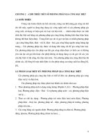
Fig.1.2-1 FANUC 0-MD(milling machine)
(1)Choose the blank function key at the left tool frame
(2)Choose reference mandril.
(3)Choose ordinance of reference mandril and thickness of spacer gauge.
(4)Preset workpiecedirectly and confirm that according to special hint on the bottom-left of
window.
(5)Coordinate Z workpiece nullpoint = current coordinate Z – length of reference mandril –
thickness of spacer gauge.
(6)Put the output:Z、Y、X axes workpiece nullpoint into G54~G59.
operation manual SSCNC introduce
3
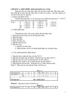
Fig.1.2-2 FANUC 0-TD(lathe)
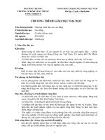
Fig.1.2-3 FANUC 0i(milling machine)
1.2.2 FUNCTON INTRODUCTION
★ The first domestic NC simulation software which can be downloaded and updated
automatically for free.
★ Vivid 3DM NC machine and operation panels.
★ Support ISO-1056 preparatory function code(G code)、secondary function code(M code)
and other operation codes.
operation manual SSCNC introduce
4
★ Support system self-defining code and canned cycle.
★ Callin CAD/CAM postposition tailor file such as UG、PRO-E、Mastercam directly for
simulation to processing.
Windows★ macro record and playback.
AVI★ files record and playback.
★ Placement and mounting of workpiece.
★ toochange mechanical hand、square-tool rest、all direction- tool rest.
★ rectifying tool by benchmark、rectifying tool by test cutting .
★ Components cutting,with processing coolant、processing sound、scrap iron and so on.
★ Tools such as edge detector、spacer gauge、micrometer、caliber rule.
★ Adopt data base management tools and performance parameter library.
★ There are many kinds of tools.
★ Support custom-defined tool function.
★ 3DM measurement function of processed model.
★ Measurement of components roughness based on cutting parameter of tools.
operation manual SSCNC operation
5
CHAPTER 2 OPERATIONS OF SWANSC NC
SIMULATION SOFTWARE
2.1 STARTUP INTERFACE OF THE SOFTWARE
2.1.1 STARTUP INTERFACE OF PROBATIONAL VERSION
Fig. 2.1-1
(1)Choose PROBATIONAL VERSION in the left document frame.
(2)Click the left window to choose NC system needed.
(3)You can also select Super Demo if needed.
(4)Click Try It to login system interface after choose one system.
2.1.2 STARTUP INTERFACE OF NETWORK VERSION
Fig. 2.1-2
(1)Choose NETWORK in the left document frame.
(2)Choose the name of system needed in the top bar-frame at right.
(3)Choose your custom name and input password in the below tow frames.
(4)Choose between Remember Me and Remember My Password.
(5)Input the IP address of server.
operation manual SSCNC operation
6
(6)Click Sign in to login system interface.
(7)Startup SSCNCSRV.exe to login the main interface of SERVER,as the following Fig. show:
Fig. 2.1-3
(8)After click the icon“CUSTOM STATUS” in toolbar,it will show all the custom
status,as the following graph show:
Fig. 2.1-4
(9)Choose a custom in Custom Statue List,and then click the icon "SET TEACHER’S
COMPUTER" to set it Teacher’s Computer.
(10)After click the icon "CUSTOM MANAGEMENT" , a dialog box " CUSTOM
MANAGEMENT " will pop-up,as the following graph show:
Add custom name and its authority in the dialog box one by one or by batch.
a. In one by one pattern, input custom name ,name, secret code and code confirmation,and also
operation manual SSCNC operation
7
you can set necessary authority then clik SAVE.
b. In batch pattern, input start numbering and number of customs, and also you can set necessary
authority then clik SAVE.
Fig. 2.1-5
2.1.3 SINGLE MACHINE VERSION STARTUP INTERFACE
Fig. 2.1-6
(1)Choose SINGLE MACHINE VERSION in the left document frame.
(2)Choose the name of system needed in the right bar-frame.
(3)Select one option between PC Encryption and Softdog Encryption.
(4)Click Run to login system interface.
2.2 SETUP OF TOOLBAR AND MENU
All the commands can be executed from the left toolbar in the window.System will show the name
of its function when cursor points each button,and meanwhile the tip help of the function will be
showed in the bottom statue bar.
Brief introduction of toolbar:
Setup new NC file
Open saved file(such NC file)
Save file(such as NC file)
Save as
Machine parametar
Cutter library management
Pattern of workpiece display
Choose size of workblank and coordinate
of workpiece
Open/close machine door
Scrap iron display
Screen arrange:change screen arrange
function by fixed sequence
Whole screen zoom up
Whole screen zoom down
Screen zoom up,zoom down
Screen translation
Screen revolve
X-Z plane selection
Y-Z plane selection
Y-X Plane selection
Machine encloser swich
Workpiece
measurement
voice controler
Coordinate display
Jacket water display
Workblank display
Component display
Clarity display
ACT display
Display tools spacing number
Cutter display
Cutter path
Online help
REC parameter setup
REC start
REC stop
teaching start/stop
operation manual SSCNC introduce
9
2.3 FILE MANAGEMENT MENU
Program file(*.NC)、tool file(*.ct)and workblank file(*.wp)callin and save and relevant
function,such as the function used to open or save data file where NC code editing process is
put.
Open
Open respective dialog box to choose the code file needed to disply the NC code in window.
Process step into auto way automatically after whole code is loaded; Schedule of code is showed
on the bottom of screen.
New
Delete NC code being edited and loaded.If code is alternated system will register that whether to
save the code.
Save
Save the code edited on the screen.If execute this command to new loaded existing file nothing
will be changed and system will ask for a new file name in despite of whether the file is loaded
just now.
Fig.2.3-1
Save as
Save a file with a new file name known to the existing name.
Load project file
Save all the relevant data files(wp; nc; ct) into a engineering file (extension name:*.pj),called
project file. This function is used to load saved file in new condition
operation manual SSCNC introduce
10
Fig.2.3-2
Project file save
This function save all the handled data into file.The blamx block on screen can be modified.
2.3.1 MACHINE PARAMETER
a. Machine parameter setup:
Drag dieblock of diago box“Parameter Setup”to choose appropriate toochange rate.
Fig.2.3-3
operation manual SSCNC introduce
11
Fig.2.3-4
Click“Color Choose”to change background color of machine.
Fig.2.3-5
Adjust“Processing Drawing Display Acceleration”and“Display Precision”to gain appropriate
speed of service of simulation software.
operation manual SSCNC introduce
12
Fig.2.3-6
b.Display color:
Click “Confirm” after choose feeding route and color of machineing.
Fig.2.3-7
2.3.2 CUTTER MANAGEMENT
a. Milling machine
operation manual SSCNC introduce
13
Fig.2.3-8
Add
(1).Input the number of tool
(2).Input the name of tool
(3). End-milling tools、buttonhead tools、dome-end tools、aiguilles、boring tools can be choosed.
(4). Diameter、length of tool hoder、rotation rate、cutting feeding rate can be defined.
(5).Click“Confirm”to add them to tool management library.
Add tool to chief axes
(1).Choose the tool needed in the tool data-base, such as tool “01”.
(2).Press mouse left key and hode it, then pull it to machine library.
(3).Add to top rest, then click “confirm”.
b.lathe
add
(1). Input the number of tool.
Fig.2.3-9
operation manual SSCNC introduce
14
(2). Input the name of tool.
(3). billmpse tool、cutting off tool、internal tool、aiguille、boring tool、screw tap、screwthread
tool、internal screwthread tool、internal circle tool can be choosed.
(4).Many kinds of cutting blade、side length of cutting blade、thicknesscan be defined.
(5). Click“Confirm”to add them to tool management library.
Internal circle tool adding:
(1)Click“add”,popup diago box“add tool”,as the fowing graph show:
Fig. 2.3-10
(2)Choose bull-nose tool in diago box“add tool”,then popup “tool”, as the fowing graph show:
(3)Choose the tool needed in diago “tool” and click “confiem”, then reverse back to “add tool”to
Fig. 2.3-11
operation manual SSCNC introduce
15
input the number of tool and the name of tool.
Add tool to chief axes
(1) .Choose the tool needed in the tool data-base, such as tool “01”.
(2). Press mouse left key and hode it, then pull it to machine library.
(3). Add to top rest, then click “confirm”.
2.3.3 WORKPIECE PARAMETER AND ACCESSORY
a. milling machine
Size of workblank、coordinate of workpiece
Fig. 2.3-12
(1)Define the length ,width and highness of workblank and its material.
(2)Define orgin of workpiece X、Y、Z.
(3)select changing machining orgin、changing workpiece.
b.Lathe
Fig. 2.3-13
operation manual SSCNC introduce
16
(1)Define workblank type, length, diameter and its material.
(2)Define fixture.
(3)Choose tailstock.
Choose workholding fixture
Fig. 2.3-14
Workpiece placement
Fig. 2.3-15
(1)Choose the placement of direction X.
(2)Choose the placement of direction Y.
(3)Choose the placement of angle.
(4)Press“Place”and“Confirm”.
Edge detector measures null point of workpiece, so choose the edge detector needed in model list.
operation manual SSCNC introduce
17
Fig. 2.3-16
Coolant pipe adjusting
Fig. 2.3-17
2.3.4 RAPID SIMULATIVE MACHINING
(1)Programme by EDIT.
(2)Choose tool.。
(3)Choose workblank and workpiece null point.
(4)Placement mode AUTO.
(5)Press the key to rapid simulative machining without machining.
2.3.5 WORKPIECE MEASUREMENT
Three modes of measurement
(1)Feature point.
(2)Feature line.
(3)Distribution of roughness.
operation manual SSCNC introduce
18
You can use Up, Down, Left and Right on keyboard to measure size, also you can input value
into diago box
Fig. 2.3-18
2.3.6 REC PARAMETER SETUP
Three modes of REC area selection,setup as
Fig. 2.3-19
2.3.7 WARING MESSAGE
Output current message files Output all message files
Last day message Next day message
Delete current message files Parameter setup
When click “Parameter setup” ,window “Info window parameter”will be appearance.
operation manual SSCNC introduce
19
Fig. 2.3-20 Font color setup Fig. 2.3-21 Gradeing standard
1. VULGAR WARINGS
Return to reference point!
Backoff measuring piercing point bar of spindle(for milling machine only)!
Program protection is locked out, and it’s unable to edit!
Program protection is locked out, and it’s unable to delete program!
Modality is not booked!Please book first!
Input format: X*** or Y*** or Z*** (FANUC measurement)!
Cutter parameter is incorrect!
There is a tool hasing this tool number, please input new tool number!
No tool hasing this tool number in top rest!
Please backoff measuring piercing point bar before auto-toochange!
Please choose the mode Auto、Edit or DNC before open file!
The file is over the Max size,so it is unable to place workpiece!
2. PROGRAMMING WARING
Search program,no O****!
Program protection is locked out, and it’s unable to edit new program number!
3. MACHINE PPERATION WARING
Electric source is not opened or intense electricity is unavailable!
Spindle startup should be in JOG、HND、INC or WHEEL mode!
Please close machine door!
operation manual SSCNC introduce
20
Startup NCSTART,then switch to AUTO、MDI、TEACHING or DNC mode!
4. VULGAR ERRORS
Please backoff spindle measurement piercing point bar before startup NCSTART
X direction overshoot
Y direction overshoot
Z direction overshoot
5. PROGRAMMING ERRORS
General G code and cyclic program are something the matter!
No O*** in program direction!
Cutter number is on-unit!
Radius compensation register number D is on-unit!
Length compensation register number H is on-unit!
Modality O*** is not booked! It can’t be deleted!
Vice program number is inexistence in subprogram call!
Vice program number is error in subprogram call!
It is lack of value F in G code!
There is no straightaway leadingin in tool compensation!
There is no straightaway eduction in tool compensation!
6. MACHINE OPERATION ERRORS
Cutter comes up against workbench!
Measuring piercing point bar comes up against workbench!
End face comes up against workpiece!
Cutter comes up against holding fixture!
Spindle is not stared,tool collision!
Measuring piercing point bar comes up against tool!
Cutter collision! Please replace small type measuring piercing point bar or raise spindle!
Teacher sends examination questions to student, and he or she can grade it which student finish
and send to teacher by Swan simulation network server. Also teacher can control the machine
operation panel of student and tips of error message.