Quy trình thử nghiệm EMC testing part 3
Bạn đang xem bản rút gọn của tài liệu. Xem và tải ngay bản đầy đủ của tài liệu tại đây (480.15 KB, 23 trang )
EMC Testing Part 3 – Fast Transient Burst, Surge,
Electrostatic Discharge
By Eur Ing Keith Armstrong C.Eng MIEE MIEEE, Partner, Cherry Clough
Consultants,
Tim Williams C.Eng MIEE, Director, Elmac Services
Both Associates of EMC-UK
This is the third in a series of seven bi-monthly articles on ‘do-it-yourself’ electromagnetic
compatibility (EMC) testing techniques for apparatus covered by the European EMC directive.
This series will cover the whole range of test methods – from simple tests for development and
fault-finding purposes, through lowest-cost EMC checks; ‘pre-compliance’ testing with various
degrees of accuracy, on-site testing for large systems and installations; to full-specification
compliance testing capable of meeting the requirements of national test accreditation bodies.
Of course, what is low-cost to an organisation of 5000 people could be thought fairly expensive
by a company of 50, and might be too expensive for a one-person outfit, but we will cover the
complete range of possible costs here so that no-one is left out. Remember though, that the more
you want to save money on EMC testing, or reduce the likelihood of being found selling non-
compliant products, the cleverer and more skilled you need to be. Low cost, low risk and low
EMC skills do not go together.
This series does not cover management and legal issues (e.g. how much testing should one do
to ensure compliance with the EMC Directive). Neither does it describe how to actually perform
EMC tests in sufficient detail. Much more information is available from the test standards
themselves and from the references provided at the end of these articles.
The topics which will be covered in these seven articles are:
1) Radiated emissions
2) Conducted emissions
3) Fast transient burst, surge, electrostatic discharge
4) Radiated immunity
5) Conducted immunity
6) Low frequency magnetic fields emissions and immunity; plus mains dips, dropouts,
interruptions, sags, brownouts and swells
7) Emissions of mains harmonic currents, voltage fluctuations, flicker and inrush currents; and
miscellaneous other tests
Table of contents for this Part
3 Fast transient burst, surge, electrostatic discharge
3.1Standardised immunity testing versus real-life reliability
3.2Hiring test gear may be the best way to Do-It-Yourself
3.3Combination test instruments
3.4Buying second-hand test gear
3.5Fast Transient Burst (FTB)
3.5.1 Details of the standard test
3.5.2 Fully compliant testing
3.5.3 On-site testing
3.5.4 Alternative FTB generators
3.6Surge
3.6.1 Fully compliant testing
3.6.2 On-site testing
3.6.3 Alternative surge test generators
3.7Electrostatic discharge (ESD)
3.7.1 Fully compliant testing
3.7.2 On-site ESD testing
3.7.3 Alternative ESD test generators
3.8Locating faults during immunity testing
3.8.1 Test instruments
3.8.2 Localised immunity testing
3 Fast transient burst, surge, electrostatic discharge
Part 0 of this series [1] described the various types of EMC test that might be carried out,
including:
• Development testing and diagnostics (to save time and money)
• Pre-compliance testing (to save time and money)
• Full compliance testing
• QA testing (to ensure continuing compliance in volume manufacture)
• Testing of changes and variants (to ensure continuing compliance).
And Part 0 also described how to go about getting the best value when using a third-party test
laboratory [1].
This part of the series focuses on testing conducted emissions to the EN standards for typical
domestic / commercial / industrial environments. Other kinds of immunity tests may be required
by the EMC standards for automotive, aerospace, rail, marine and military environments. In
particular, the conducted transients and surges in an automotive environment (internal
combustion engine with spark ignition, driving an alternator, which charges a battery) can be very
different indeed from those typical of a building connected to a 230/415V mains power supply, as
shown by ISO 7637 [2], for example. These industries have over the years developed their own
test standards based on their own particular kinds of disturbances, for reliability reasons.
IMPORTANT SAFETY NOTE: Some of these tests involve electrically hazardous conductors
(e.g. mains), and/or hazardous voltages or energies. These tests can be dangerous, and all
appropriate safety precautions must be taken. If you aren’t sure what safety precautions are
needed, ask an expert.
The basic EN test methods described here are identical to the basic IEC test methods (e.g. EN
61000-4-4 is identical to IEC 61000-4-4), so this article may also be of use where non-EU EMC
specifications apply.
3.1 Standardised immunity testing versus real-life reliability
These three immunity tests use carefully-defined generators with carefully-defined waveforms
and test set-ups to try to achieve a repeatable test. There is plenty of experience to show that the
tests are not as repeatable as one might wish, and the standards are continually being developed
to try to improve this (read [3] for more on this issue).
But it is important to realise that these standards do not necessarily simulate the real-world
electromagnetic disturbances very well. The waveforms specified by their tests are more likely to
reflect what it is possible to generate cost-effectively and repeatably in a laboratory instrument,
than be an accurate simulation of the disturbance waveforms present in real applications.
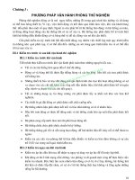
For example, the fast transient burst test aims to simulate the disturbances created by a
‘showering arc’ at the contacts of an ordinary AC mains switch or relay contacts as it opens. The
inductance of the mains cable (plus any in the load) causes a flyback voltage at the instant the
current is interrupted, and the flyback voltage rises until it is sufficient to break down the air gap at
the contacts and make an arc. When the arc stops the flyback occurs again, this time with the
contacts slightly further apart. So during the opening of a switch or relay contact the transients
generated can look something like Figure 3A, starting off with a low amplitude and a high
frequency (could be MHz) and with rising amplitude and falling frequency as the contact gap
widens. Compare this with the waveform of the standard EN 61000-4-2 test in Figure 3C, which
uses a constant amplitude and frequency (5kHz).
It is true to say that a product designed to meet these standards will generally be more reliable
(all things being equal) than one which has been designed with little or no thought to surviving
these disturbances and no testing. But meeting these standards does not guarantee freedom
from errors or failure in the field due to the disturbances represented by these three standards.
For example, surge testing according to EN 61000-4-5 is called up by the generic standards and
most of the other immunity standards harmonised under the EMC directive, usually at the level of
±1kV for line-to-line surges and ±2kV for line-to-ground. However, it is well known (and
recognised by some lightning protection standards) that in Europe and the USA at least the mains
power in typical urban buildings will suffer from line-to-ground surges of 6kV at least once per
year. This is caused by normal thunderstorm activity in the local area, not direct strikes, and
applies to buildings which do not have lightning protection systems designed to protect
electronics. Rural buildings whose mains supply is carried by overhead conductors, can reckon
on experiencing many tens or hundreds of 6kV surges every year, depending on the length of
their overhead line.
The figure of 6kV arises because the typical domestic-style mains sockets flash-over at their rear
connections at around this voltage and so act like spark-gap suppressers. In industrial premises
mains distribution using three-phase supplies fitted only with the larger three-phase mains
sockets might suffer from line-to-ground surges of well over 6kV due to the increased flash-over
voltage of these sockets. It is ironic that in buildings whose mains wiring has poor quality
insulation, the maximum surge voltages can be much less – due to the accidental spark-gaps
(which are also fire hazards) created by the poor quality wiring.
One of the authors has experience of a mains power supply module widely used in Europe that
suffered from an excessive failure rate. This turned out to be due to the fact that the creepage
and clearance distances between the track to the gate of a switching power FET and the earthed
chassis were inadequate at over 5kV (when testing with the EN 61000-4-5 waveshape). These
modules would clearly pass all the immunity standards harmonised under the EMC directive, but
were almost certain to fail at least once per year in most indoor urban environments in Europe
and the USA.
Another example relates to electrostatic discharge (ESD). The test standard called up by EMC
directive harmonised immunity standards is EN 61000-4-2, but this only covers personnel
discharge (e.g. from people’s fingers, keys, etc.). Leaving aside questions about the accuracy of
its simulation of actual personnel ESD events into a variety of real-life load impedances, it does
not even try to address other types of ESD events which may be very important in real-life
applications, such as furniture ESD and machine ESD. Machine ESD can be very severe indeed
in some industries, especially where webs of insulating material (paper, plastic film, etc.) or
insulating gases, dusts (e.g. flour) or liquids are processed. Even a motor running in plastic
bearings can generate severe ESD events between its rotor and its stator. There are almost as
many possible ESD waveshapes as there are applications with machine-ESD problems.
So, where it is desired to create reliable products, the EMC immunity work done should go
beyond the standard EMC directive immunity tests:
• Consider whether the test levels on the standard EMC directive immunity tests should be
increased to address the real-life situation for disturbances with a similar waveshape.
• Consider whether the real-life disturbances in the intended environment are sufficiently
different from the EMC directive’s standard tests to make a different type of test necessary.
• Where a standard test method does not exist to cover your real-life environment, with a little
ingenuity it is often possible to design your own fast transient burst, surge, or electrostatic
discharge tests that simulate the expected environmental threats. Sometimes this requires
little more than replicating whatever it is that is causing the threat (e.g. a 10kVA transformer
and its on/off contactor) or – if this would require too much work – taking prototype products to
where the threat exists.
The financial rewards of producing reliable products can be very great indeed, as one UK
manufacturer discovered when they spent £100,000 on redesigning their products to comply with
the latest EMC directive immunity standards, and then discovered that as a direct result their
warranty costs fell by £2.7 million per year.
3.2 Hiring test gear may be the best way to Do-It-Yourself
Unlike the emissions tests described in Parts 1 and 2 of this series [1] [4], using alternative test
generators for these three tests cannot give any confidence whatsoever that compliance tests to
the proper standards would be passed (even though such tests may be valuable for improving the
reliability of a product).
Many rental companies have stocks of the calibrated test gear needed to do FTB, Surge, or ESD
tests properly, and will rent them out for daily, weekly, or monthly periods. The easiest way to
perform these tests with reasonable accuracy and lowest cost is often to hire the equipment and
do the tests yourself.
The test set-ups for these tests are not difficult to achieve in a typical manufacturing company, as
they don’t need special test chambers or open area sites, at the most just an area of ground
plane and a wooden table. EMC test laboratories often do these tests inside metal shipping
containers or low-cost shielded rooms, but this is to help prevent the tests interfering with other
EMC tests that might be going on nearby. Where nothing very sensitive is nearby, such
precautions are not needed.
With enough skill and attention to detail, hired test gear can readily be used to do fully compliant
testing on these three immunity tests.
3.3 Combination test instruments
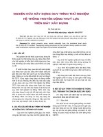
A few EMC test equipment manufacturers now supply combination immunity testers. A typical
example is the unit shown in Figure3B, which costs in the order of £9,000 when the options and
accessories for EN 61000-4-2, -4, and –5 are specified.
As a means of saving space, weight, and cost, these combination instruments are an excellent
way to achieve compliant testing on your own premises. If you find you are hiring test gear
frequently or for long periods, it is a good idea to do a financial analysis based on a two-year
break-even to see if it is worth buying the test gear outright.
3.4 Buying second-hand test gear
Some rental companies sell off their rental equipment after a few years, and second-hand test
gear is also available from a number of other sources. An un-expired calibration certificate on a
second-hand purchase is well worth having, if only because it makes the possibility of expensive
repairs to achieve your first calibration less likely.
When buying second-hand immunity test gear it is very important indeed to check that it is
capable of testing the versions of the standards that you need to use. Some of the test gear is
only available second-hand because it is not capable of performing compliant tests to the latest
versions of the relevant immunity standards. Such equipment should cost less than compliant test
gear, and may still be useful for preliminary investigations where money is tight.
3.5 Fast Transient Burst (FTB)
3.5.1 Details of the standard test
The FTB test aims to simulate the disturbances created by a ‘showering arc’ at the contacts of
ordinary AC mains switches or relay contacts as they open, due to the flyback voltages caused by
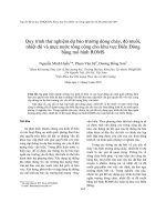
inductive energy storage in the current path. Figure 3C shows the standard waveform for the EN
61000-4-4 FTB test. It consists of a single unidirectional impulse repeated at a 5kHz rate in bursts
lasting 15 milliseconds each, with three bursts per second. Figure 3D shows the basic scheme of
the waveform generator and Figure 3E shows the standard test set-up. These three figures are all
developed from the EN 61000-4-4 standard.
Anyone wishing to perform an FTB test should have a copy of the relevant version of the basic
test standard EN 61000-4-4 and follow it as closely as they need to for the test accuracy they
require, or can achieve with their test gear.
AC and DC power cables have the transient bursts injected directly into them via specified
coupling-decoupling networks (CDNs). These CDNs are contained within proprietary FTB test
instruments, but can also be made by following the instructions and schematics in EN 61000-4-4.
Signal and data cables have the transient bursts injected via a specified capacitive clamp. These
clamps are easily made using common materials by following the detailed construction drawing in
figure 5 of EN 61000-4-4. The clamp can also be replaced with wound tape or conductive foil 1
metre long that creates the equivalent capacitance to the standard clamp (100pF). Shielded
‘Zippertubing’ 1 metre long on an insulating support can be a simple alternative to a clamp.
Where the 1 metre length of the clamp or equivalent is too long, alternatives can be used as long
as they give the equivalent capacitance, even to the extent of connecting the output of the
generator directly to the cable screen or signal terminals via discrete 100pF capacitors (high-
voltage ceramic type). Because of the lack of distributed coupling, these alternatives (especially
the discrete capacitors) are likely to give different results from the standard clamp method so
should be used with caution, and only where the 1 metre clamp can’t be used.
When testing signal and data cables be aware that the capacitive clamp has no directionality, so
any auxiliary equipment being used in the test set-up is also subject to the FTB on its cables.
Suppression techniques may be needed for the auxiliary equipment (such as passing the cables
through a bulkhead-mounted filter in a screened-room wall, and/or clip-on ferrite cable
suppressers) to allow the EUT’s response to be measured correctly. Suppressers based on
chokes and ferrites are preferred, as capacitive filters may prevent the signal cable from
experiencing the coupled FTB as it will in a real application.
3.5.2 Fully compliant FTB testing
The EN 61000-4-4 standard basically consists of three things: a description of the burst
generator, a description of the test layout and instructions for the test procedure. We have seen
the specified burst waveform in Figure 3C. This is calibrated into a 50Ω load, but of course the
actual test load is anything but 50Ω, since it depends entirely on the EUT. Thus the waveform of
the burst applied to the EUT may be different, and particularly, may vary between different
models of compliant generator. This is a recognised problem with the standard as it exists at
present, and an amendment is shortly to be published which will correct it, by requiring extra
calibration steps. Note also that the applied test level is specified as the open-circuit peak
voltage, not the calibrated voltage; again, this open circuit level is not the voltage which appears
at the EUT, which depends on the ratio of generator source and EUT load impedances.
The FTB is a wideband phenomenon with spectral components up to hundreds of MHz, and
therefore as with other RF tests, layout is important for repeatability. The coupling of the burst is
strongly dependent on the EUT’s stray capacitance to its surroundings. Layout aspects which
must be observed are:
• The coupling of the EUT and generator to the ground plane. You cannot perform a compliant
FTB test without a ground plane. It must be at least 1m square, and should extend beyond the
EUT by at least 10cm all round. The burst generator is bonded to it – by a short strap, not a
length of wire, and this means that the generator will normally sit on the floor, not on an
adjacent table. (This makes remote software control of the generator more desirable, as a
remedy for backache. Alternatively the ground plane could be at table-top height, as long as
other distances are maintained.) The EUT is spaced from the ground plane by 10cm or, for
table-top equipment, 80cm. The 80cm high wooden table is used here as in many other EMC
tests.
• Clear distance around the EUT. The minimum distance from the EUT to all other conducting
structures – and this includes the test generator and capacitive coupling clamp, a condition
which is sometimes forgotten – must be 0.5m. The coupling clamp itself must also have a
clear distance around it of at least 0.5m.
• Earthing of the EUT: if it will be separately earthed in the real installation, then it must be
connected to the ground plane in a representative manner, otherwise no connection is made.
• Cable layout: the distance between the EUT and the coupling network or clamp must be 1m or
less. Long cables should be coiled with a 40cm diameter, 10cm above the ground plane –
note that this differs from the treatment prescribed for emissions tests. It is wise to maintain
the cable separation of at least 10cm from the ground plane under all conditions and for all
cables, not just the one being tested.
• The capacitive clamp itself must be directly bonded to the ground plane. This introduces a
conflict for EUTs which have cable entries greater than 1m above the floor, since either the
cable must be further than 1m from the clamp or the clamp has to be raised above the floor.
There is no firm guidance on resolving this problem, but we would suggest that it is more
important to bond the clamp to the floor so that the induced stress is repeatable at that point,
and accept a longer cable, as long as its route is carefully controlled. But there may be
arguments for the alternative approach in some circumstances.
The procedures for applying the bursts are generally straightforward – the standard requires at
least one minute for each coupling mode, which for a repetition period of 300ms means at least
200 bursts. The product or generic standard being invoked will determine which ports are tested.
In contrast to the other tests, only the specified test level need be applied, although you may well
want ramp through the levels to check for lower- and higher-level susceptibilities. For the clamp
application, this means that only two minutes’ testing is needed per port, once in each polarity.
For mains supply tests, you have the possibility of applying the bursts to any combination of the
supply wires: L, N, E, L+N, L+E, N+E, and L+N+E (for single-phase earthed supplies), since all of
these are tested with a voltage that is referred to the ground plane. The standard merely shows
an “example” of coupling via a coupling/decoupling network, and does not mandate any particular
combination (see Figures 3F and 3G). A few early product and generic standards refer to testing
with EFT bursts in “common mode”, which could be interpreted as requiring application to L+N+E
only. The issue from the point of view of compliance could be significant, since immunity often
varies markedly between these different modes of application. As a general rule, we would advise
you to apply all the separate combinations, since in a real situation the coupling could be
dominated by any particular one of them.
3.5.3 On-site testing
On-site FTB testing to EN 61000-4-4 is easy to do, because of the relatively simple test set-ups
required, the portability of the test gear, and the fact that suitable methods are described by the
standard. Chapter 10 of [5] also describes on-site FTB testing, which requires the use of a 1
metre square reference plane. On-site testing is best restricted to proving that an installation is
not susceptible, rather than declaring EMC conformity for a product using the ‘standards’ route.
However, an EMC Competent Body could well accept on-site testing when following the
Technical Construction File (TCF) route to EMC compliance, especially for custom equipment
intended for a specific site.
Figure 3H shows an example of on-site testing of the mains lead of an industrial cabinet. In this
case the generator did not use the 1 metre square additional plane specified by the standard so
there would be some increased variability expected in the results.
The variability of non-standard test set-ups may be able to be offset to some degree by
overtesting, say by testing at up to double the level required by the relevant immunity standard.
Of course, the non-standard test method might already be making it a more aggressive test, so
increasing the test level might result in a very aggressive test indeed and lead to over-
engineering of the product. This is part of the price you pay when you deviate from the standard
test method.
3.5.4 Alternative FTB generators
IMPORTANT SAFETY NOTE: Never use an unsafe test method or take risks with electricity. If
you haven’t been fully trained in electrical safety, call in someone who has (and who passed the
exams).
A wonderful variety of showering arc simulators exist in companies all over the world, some of
them very hazardous to use. An old favourite which is perfectly safe providing the basic electrical
safety precautions are taken, is the ‘chattering relay’ test shown by Figure 3J.
The chattering relay can be used in a wide variety of ways to generate radiated and/or conducted
disturbances. If it is supplied via a safety-isolating transformer (or from a floating DC supply) with
sufficient voltage withstand, the bottom side of the coil could be connected to the reference plane
(or to any other conductor) and the top of the coil (the node that connects to the relay contact)
could be connected via a high-voltage ceramic capacitor to any conductor. This would allow
transients to be generated from line-to-line (i.e. differential mode) and each line-to-ground, or all
lines-to-ground (common mode).
A popular alternative to the chattering relay is the electric bell. The actual bell dome should
always be removed, to avoid the risks of physical injury to the test engineer by nearby colleagues
(noise isn’t so annoying when it is you that is making it). The electric bell has the advantage that
the relay contact gap can usually be adjusted to increase the frequency (at decreased amplitude)
or decrease the frequency (at increased amplitude) – a degree of control that is not usually
available with relays.
IMPORTANT SAFETY NOTE: Don’t forget that the sparks from chattering relays or electric bells
can easily ignite flammable materials.
Such simple transient generators can be used as very low-cost alternatives to proper EN 61000-
4-4 test instruments. Their usefulness can be increased by golden product testing on a particular
product (see section 1.9 of [1] for more on this). They may then be useful for QA testing in
production or for testing new variants or new products that use the same circuit techniques and
exactly the same ICs. When alternative sources of ICs are used, or significant changes made to
any aspect of the design (including software) the correlation with ‘proper’ FTB testing is lost and
would need to be re-established by a new golden product.
However, as mentioned in 3.1 above, it may be that the home-made transient test
is more representative of the real-life operating environment of the product than is the standard
EN 61000-4-4 test. In such cases the test circuit (e.g. a 10kW motor and on/off contactor) should
be set-up and related physically to the EUT as close as possible to the real-life situation
(proximity, connections to the same supplies, etc.). In the case of a rotating device such as a
motor, the energy stored in the rotating parts can significantly affect the transients and surges
which are injected into the supply at switch-off, so it is better if the relay or contactor is operated
in such a way as to allow the motor sufficient time to speed up and slow down.
When self-declaring compliance to the EMC directive using the ‘standards route’, even if
chattering relay or similar tests have been done to simulate the operating environment and help
achieve reliability, it is still best to test to (and pass) EN 61000-4-4 to help avoid the possibility of
legal challenges in the future.
But when following the Technical Construction File (TCF) route it may be possible to persuade
your Competent Body that the tests you have done represent the environment that the product is
going into, and there is no need to apply EN 61000-4-4 as well. This is most likely only possible
for custom-designed industrial equipment going into known sites, and not for portable products or
equipment which could be used in a range of premises.
3.6 Surge
The surge test aims to simulate the effects of lightning on AC power supplies and any long
cables. ‘Long cables’ is usually taken to mean metallic interconnections longer than 10m between
different items of equipment which are themselves some metres apart, or outdoor cables.
Figure 3K shows the standard waveform for the EN 61000-4-5 surge test, which is a single
unidirectional impulse specified by two waveforms at the same time: as a 1.2/50µs voltage
impulse into an open-circuit, and as a 8/20µs impulse into a short-circuit – leading to its common
name: the ‘combination wave’. The standard surge waveform for testing telecommunication
cables (that exit a building) has a broadly similar shape, with a 10µs rise time and 700µs fall time.
When testing mains inputs the surges are applied (as a positive or negative voltages) at all the
zero-crossings and the peaks in a cycle of mains waveform. Time is allowed between each
impulse to avoid overheating surge protection devices (SPDs).
Figure 3L shows the basic scheme of a surge waveform generator and Figure 3M shows the
standard test set-up. These three figures are all taken directly from the EN 61000-4-5 standard.
Anyone wishing to perform a surge test should have a copy of the relevant version of the basic
test standard EN 61000-4-5, and follow it as closely as they need to for the test accuracy they
require.
The frequency spectrum of the surge test is much lower than that in the FTB or ESD tests, and so
the test set-up does not need a reference plane (of course it requires an earth, but ordinary wired
earth connections will do.) But be aware that the surge current can reach kilo-amps, so the wiring
between the generator and the equipment under test must be robust.
IMPORTANT SAFETY NOTE: The instantaneous power and total energy in an EN 61000-4-5
surge test can be quite large – enough to cause electronic devices to explode and eject burning
fragments with considerable violence. For this reason surge tests should only be carried out
where third parties are positively excluded, and the entire bodies of all operators and others
witnessing the tests should be protected at least by a substantial acrylic or other plastic sheet.
Fire extinguishers suitable for electrical fires should also be kept charged and handy, and the
location of the mains isolator for the whole test area and EUT should be known and it should be
readily accessible.
3.6.1 Fully compliant testing
Because of the lower frequency spectrum content of the surge waveform, surge testing is more
tolerant of layout variations than the other tests discussed in this article, and the standard is fairly
relaxed in this respect. The cable between the EUT and the coupling/decoupling network should
be 2m or less in length. Otherwise there are no restrictions on the layout.
The surge waveforms as shown in Fig 3K should appear at the output of a compliant generator
when it is calibrated with a short circuit and an open circuit load. The waveform through the mains
coupling/decoupling network must also be calibrated and be unaffected by the network, but for
coupling devices for signal lines this requirement is waived. The signal line coupling networks
include a 40Ω series resistor, which reduces the energy in the applied surge substantially. For
mains coupling, the generator is connected directly via a 18µF capacitor across each phase, but
through a 10Ω resistor and 9µF capacitor for phase-to-earth application. This means that the
highest energy available from the generator’s effective source impedance of 2Ω is actually only
applied between phases.
Coupling to signal lines can be problematic since it has to be invasive; no clamp-type devices are
available for this test. However for signal lines that would be affected by a 0.5µF capacitor
connected to them, it is permissible to use gas discharge tube (surge arrestor) coupling instead.
A separate method is shown in the standard for shielded lines, in which the surge is effectively
applied longitudinally along the shield, by coupling it directly to the EUT at one end of a non-
inductively bundled 20m length of cable, with the further end grounded. This test is carried out
with no series resistor, so that the surge current down the cable shield will be several hundred
amps.
The test procedure requires you to take the following steps (see Figure 3N), bearing in mind that
an agreed test plan may modify them:
• Apply at least five positive and five negative surges at each coupling point
• Wait for at least a minute between applying each surge, to allow time for any protection
devices to recover
• Apply the surges line-to-line (three combinations for 3-phase, one for single phase) and line-to-
ground (two combinations for single phase, three for 3-phase)
• Synchronise the surges to the zero crossings and the positive and negative peaks of the mains
supply (four possibilities)
• Increase the test voltage in steps up to the specified maximum level, so that all lower test
levels are satisfied
• Apply a sufficient number of pulses to find all critical points of the duty cycle of the equipment.
Ignoring the last, which doesn’t give any specific guidance for how many pulses would be
sufficient, a worst case interpretation of the requirements on a 3-phase supply being tested up to
level 4 would imply that a single complete test would take 16 hours, not allowing for set-up and
test sequencing time. Test labs know that their customers would be uncomfortable with this, and
usually some shortcuts are taken so that not all these steps are followed rigorously. This though
means that the various interpretations that the standard encourages can lead to different degrees
of stringency in testing.
The rationale for “all lower levels must be satisfied” is that the behaviour of many types of surge
suppression is likely to vary between low and high values of surge voltage. A suppresser that
would break down and limit the applied voltage when faced with a high level, may not do so at
lower voltages, or may at least behave differently. The worst case could well be at just below the
breakdown voltage of an installed suppression device. Equally, the EUT response can change
either because of circuit operation or because of suppresser behaviour when the surge occurs at
varying times during the mains cycle. For example, an unfiltered circuit that looks for zero
crossings will have an undesired response when a negative-going surge occurs at the positive
peak of the cycle. Unless you are very confident of your EUT’s performance in these various
conditions, it makes sense to apply testing over as wide a range of variables as possible. This is
the merit of pre-compliance testing: to inform the test plan for the full compliance test so that
confidence can be had in a restricted set of tests which takes a reasonable length of time.
3.6.2 On-site testing
On-site surge testing to EN 61000-4-5 is very easy to do, because of the relatively simple test
set-ups required, the portability of the test gear, and the fact that no reference plane or shielded
room is required. Annex B of EN 61000-4-5 describes what it calls ‘system level testing’, which it
recommends to demonstrate reliability in an installation rather than compliance with any
regulations. However, it may be possible to get an EMC Competent Body to agree to accept on-
site testing when following the Technical Construction File (TCF) route to EMC compliance,
especially for custom equipment intended for a specific site.
3.6.3 Alternative surge test generators
Because of the very definitely lethal voltages, stored charge, and energy involved in a surge test
generator, we do not encourage anyone to build their own (unless they are very experienced with
designing high-voltage equipment for safety and will be applying a safety standard such as EN
61010-1 in full). No example do-it-yourself circuits are therefore given here.
Where large inductive loads are switched, the stored energy they contain can do a lot more than
merely create some showering arcs in their switch contacts. Joules of energy in the collapsing
magnetic fields of motors, transformers, and other power inductive devices can transfer large
surges to their power supplies in the arcing of their switches, relays, or contactors, as they open.
Here is another example where the standard EN 61000-4-5 test may not represent the surges
that a product is exposed to in its intended applications. Surges due to inductive load collapse
may be a lot faster than lightning induced surges, and may also have more energy in them. An
example of a 10kW motor and on/off contactor was used earlier. Where such large inductive
loads may be connected to the same branch of the mains distribution and no special surge
protection is applied by the installation, testing with a representative surge generator may help
improve reliability in the field and reduce warranty claims. (In the case of a motor, the rotational
inertia of its load is not important unless the motor is capable of significant generation efficiency
when not energised remotely.)
An extreme example of a problem load is the superconducting magnets used in MRI scanners.
These can take several weeks to charge up from kA rated power supplies, and when their field
collapses they can put surges of around 1MJ back into their supplies, and any other conductors
they can arc across to, in just a few microseconds. This is approximately 10,000 times larger than
the energy in an EN 61000-4-5 mains surge test at 1kV, and capable of destroying structural
metalwork rather like a direct lightning strike. MRI scanner manufacturers almost certainly take
whatever steps are necessary to absorb these surges, if only to protect the electronics in their
own product.
At a more mundane level, designing to pass a suitable surge test can be very helpful in reducing
field returns due to thunderstorm activity – rarely a serious problem in the UK, but much more so
in some other parts of the world, where the infrastructure to deal with such returns is harder to set
up.
3.7 Electrostatic discharge (ESD)
The ESD test aims to simulate the effects of discharges from the fingers of personnel, either
directly or via keys or other metal objects held in the hand, the personnel having been charged to
a high voltage by tribo-electric charging, usually due to rubbing contacts between their shoes or
clothing and dissimilar materials used for flooring, storage, etc.
Figure 3P shows the standard waveform for the EN 61000-4-2 ESD test, which is a single
unidirectional impulse. Figure 3R shows the basic scheme of an ESD generator or ‘gun’ and
Figure 3S shows the standard bench test set-up. These three figures have all been developed
from the EN 61000-4-2 standard.
Anyone wishing to perform this type of personnel ESD test should have a copy of the relevant
version of the basic test standard EN 61000-4-2, and follow it as closely as they need to for the
test accuracy they require. Compliant ESD guns are easy to hire and relatively straightforward to
use, and an example of one is shown in Figure 3T.
3.7.1 Fully compliant testing
In contrast to the two previous test types, where the mode of coupling of the transient is
reasonably well defined, the ESD test – even done fully according to the standard – is not well
controlled. Much depends on the skill and experience of the test engineer, particularly in selecting
the test points and in actually applying the stress.
The basic layout is straightforward. The EUT is placed over a ground plane to which the ESD
generator is returned. This must project at least 0.5m beyond the EUT or coupling plane, i.e.
further than is required for the EFT test. The ground return lead is calibrated with the generator
and this should be exactly the same lead as is used for the testing. Different leads will have
different inductances, and this could modify the discharge waveform, particularly its trailing edge.
The lead should always be kept away from the EUT and other structures (by 0.2m minimum,
according to the standard), and the test engineer’s body. The separation distance for the EUT
above the ground plane, as with the EFT burst test, is 10cm for floor standing and 80cm for table-
top apparatus. (The distance of 10cm here is helpfully the same as the thickness of a fork lift
truck pallet.) There should also be at least 1m clear area around the EUT.
For table-top testing, directly underneath the EUT but insulated from it there is a secondary plane,
known as the horizontal coupling plane (HCP). This is connected to the ground plane by a bleed
resistor lead. The construction of this lead is important: its purpose is to isolate the HCP during
the actual discharge but allow charge to bleed off afterwards. The resistors are located at each
end of the lead so that the lead’s stray inductance and capacitance are isolated from both the
HCP and the ground plane. Since the resistors must withstand nearly the full applied ESD
voltage, they should be large enough to prevent tracking across their surface. Carbon
composition (not carbon or metal film) are good for these components.
The (table-top) EUT is placed on the HCP with its front face 10cm from the edge of the plane.
Cables are draped off the HCP and taken away from the test area as necessary. In fact the
standard is weak in this respect: although as with other RF tests cable layout and termination can
make a large difference to the test outcome, EN 61000-4-2 says virtually nothing about how they
should be treated, except that they should be “representative of installation practice”.
The procedure followed in the test is divided into direct application of contact and/or air
discharges, and indirect contact application to the coupling plane(s). The discharge gun itself is
capable of both contact and air discharges. For the contact discharge, the pointed tip makes
contact with the test point, and to create a pulse a relay within the unit is closed, which applies
the test voltage to the tip. This removes the variability associated with the breakdown of the air
gap in the air discharge method, and it is the preferred method wherever a conducting surface is
accessible. But if your EUT has insulating surfaces where a discharge might still be possible, the
air discharge method using a rounded tip is still necessary. Favourite spots are apertures or
seams in a plastic enclosure, behind which there may be metallisation or metal parts, and the
gaps between key caps or around windows.
The ESD gun must be held perpendicular to the surface being tested, since any departure from
this affects the stray capacitance between the front of the gun and the EUT, and is a source of
variability. In addition when doing the air discharge, you should be positive in your handling of the
gun. The standard says “the tip shall be approached as fast as possible (without causing
mechanical damage) to touch the EUT”. This is important, because the stress applied is greatly
affected by the approach speed. A wavering, cautious approach will result in large variations of
stress between discharges.
The indirect discharge to a vertical coupling plane, and to the HCP for table-top equipment, has
also to be performed for all types of product. This is a contact test only, i.e. the air discharge tip is
not used. It simulates the effect of a discharge to a nearby conductive object. In the case of a
well-insulated product, it is in fact the only test in which a discharge actually occurs. In many
cases this is less stressful than a direct discharge and a good product will be unaffected by it, but
you cannot assume this until the test has been done. Amendment 1 to the standard modifies the
method to make clear that the gun should be held edge-on to the plane, at the centre of the face
of the EUT, which is different from the original standard’s wording. You will usually have to rotate
the EUT to test all four sides; this is likely to be easier than making sure that each appropriate
face of the EUT is 10cm from the edge of the HCP.
The actual application of a compliance test should proceed as follows:
• Select a suitable set of points for the test application, and make sure that you document these
with reference to a drawing of the product. You may have a good empirical idea of the likely
weak points – for instance the edges of aperture, seams or joints, or control or ventilation
openings – or you have already done some exploratory testing at a fast pulse rate to actively
identify such points.
• At each point and for each test voltage you will apply at least ten pulse discharges, allowing at
least a second in between, checking for the EUT’s response. Unless you know the most
sensitive polarity, apply ten discharges in each polarity. This could be ten positive followed by
ten negative, or alternate positive and negative, or any combination in between. Provided that
the EUT discharges after each pulse it shouldn’t matter how you do it, although this may
depend on the design of the EUT.
• For each point and each of these sets of discharges, start off at the lowest test level (2kV) and
ramp up through the levels to the specification value, typically 4kV for contact and 4kV + 8kV
for air. This is to check for non-linearities in the stress response and is a requirement of the
standard.
The test is only required at such points and surfaces which are accessible to personnel during
normal use of the equipment. This may mean that some potentially susceptible points need not
be tested directly. A second amendment to the standard, published in November 2000, gives
clearer guidance on what is meant by accessible points. It also clarifies the procedure for
ungrounded EUTs. If the applied charge cannot bleed off the EUT between pulses – because, for
example, it has no external connections – then the stress voltage will change after each pulse
application. This will either reduce the applied stress, if the voltage on the EUT rises towards the
applied value on consecutive applications of the same polarity, or it will increase it, if the polarity
is changed between applications. To deal with this you need to ensure that the EUT is properly
discharged each time. The amendment recommends that a bleed resistor cable is attached to the
EUT during the test, as long as this will not affect the test outcome. Otherwise, a bleed brush can
be applied after each pulse, or an air ioniser can be used.
The root ESD test standard IEC 61000-4-2 has been around since 1995 and it was virtually
unchanged from the original IEC 801-2: 1991 document. It has stood the test of time reasonably
well, but enough experience has been gained to lead to the desire for a complete revision. A first
draft of this revision (IEC 61000-4-2 second edition) was circulated on 5th January 2001. This is a
complete re-write of the existing standard: anybody concerned with ESD testing or test equipment
should read it. The major novelties are described below.
• The number of tests has been increased to 50 on each test point
• A clear area around the test site is defined
• The generator specification is substantially more detailed
• There are new requirements for calibration
• There are extra requirements on the GRP, HCP, VCP and bleed wires
• In the setup: the EUT cables are to be terminated with CDNs or EM Clamps; there is a new
setup for “small” table-top EUTs; the method for ungrounded equipment is included as per A2
to the first edition
• There is more detailed guidance on test methods; for contact discharge, it is no longer
necessary to satisfy all lower levels, though it still is for air discharge
• An “escalation strategy” is presented for difficult-to-reproduce failures
• There are several new guidance annexes.
3.7.2 On-site ESD testing
On-site ESD testing to EN 61000-4-2 is very easy to do, because of the relatively simple test set-
up required and the easy portability of the test gear (e.g. the ESD ‘gun’ shown by Figure 3T is
battery powered and comes with a spare battery pack so one can be charging while the other is
in use). In addition, section 7.2 and Figure 7 of EN 61000-4-2 describe what it calls ‘post
installation tests’ which merely require the addition of a 0.3 x 2 metre reference plane, also quite
a portable item. On-site ESD tests are also described in considerable detail in chapter 10 of [5].
3.7.3 Alternative ESD test generators
Figure 3U shows the old favourite, the modified piezoelectric gas lighter. These can be purchased
for a very low cost (a few £) and easily modified to make a crude ESD gun. Their output
waveforms are unknown (although they could perhaps be calibrated by using an EN 61000-4-2
style calibration fixture) and they work on the principle that some sort of ESD testing is a lot better
than nothing.
Alternative ESD generators can easily be made using the spark ignition circuits used in gas or oil-
fired boilers. Another alternative is to use an automotive ignition coil and circuit, with the coil
energised by a simple monostable driving a power FET or relay. It is also possible to make high-
voltage generators from TV set circuits, or from ladder networks, or neon lamp power supplies. In
all cases a carefully insulated hand-held probe is required, with a hemispherical tip of 8mm
diameter to match the air-discharge tip in EN 61000-4-2. Of course, all these different generators
will have quite different characteristics, and those that use inductive or piezo-electric components
to directly produce the high voltage spark will most probably not achieve the very fast rising edge
of the proper ESD test which causes much of the disruption experienced by typical digital circuits.
Home-made ESD guns can have their output voltage controlled in the same way that a ‘proper’
air-discharge ESD gun can – by setting the instrument to continuous discharge when it produces
one spark every second, or fraction of a second depending on the internal HT generator’s
capability (an automotive spark generator should be capable of 100Hz spark rate) – and then
varying the distance of the discharge tip from the target. Since the breakdown of air is
approximately 1kV/mm, a gap of 4mm gives sparks at approximately 4kV, and a gap of 15mm
gives a spark of 15kV.
With a little practice you will be able to explore the ESD weaknesses of your product very quickly,
whether using a compliant ESD gun or a home-made one, by setting the gun to continuous
operation and moving the probe tip over the product’s surfaces while varying the tip distance from
2 to 10mm so as to expose each tested point to a wide variety of test voltages.
Given the low cost of hiring a compliant ESD gun and the very low cost of the test set-up there
seems little point for most companies to make their own ESD gun and then having to worry about
whether they are over-testing or under-testing, or just testing their product differently.
But it may be that a home-made ESD simulator is needed to simulate an actual environmental
threat, such as the discharges from a particular industrial process, as an aid to reliability in the
field rather than any concerns about regulatory compliance. When constructing such simulators, it
is important to get the charging capacitance and the impedance of the discharge path reasonably
accurate (within 50% is probably the ESD equivalent of perfection), and this may involve some
measurements of the construction of whatever it is that is causing the discharge (almost always a
metal object) and a reasonable amount of empirical calculations. Note that the polarity of the
discharge is often important, as many electronic circuits can behave differently with the same
voltage levels but different polarities.
IMPORTANT SAFETY NOTE: EN 61000-4-2 ESD discharges are not dangerous (although they
are not recommended for anyone fitted with a pacemaker or other implanted or body-worn
electronics) but custom-made ESD generators could well be lethal. EN 61010-1 says that
voltages up to 15kV peak or DC are considered unsafe if they can discharge > 45µC (micro-
coulombs), and voltages above 15kV are unsafe if the energy associated with them exceeds
350mJ (milli-Joules), and it is probably wise to follow the guidance of this safety standard and
take all necessary personnel high-voltage protection measures if these limits are exceeded. 45µC
implies a maximum value of capacitance of 3nF at a voltage of 15kV (or 5.6nF at 8kV). For
inductively-generated ESD at under 15kV it is probably safest to apply the 350mJ limit.
3.8 Locating faults during immunity testing
3.8.1 Test instruments
As anyone who has tried has discovered, regular test instruments (digital multimeters,
oscilloscopes, logic analysers, etc.) are usually quite useless during immunity testing. Either they
are so perturbed by the test itself that it is hard to tell what, if anything, is being measured; or the
impedance of their probes so affects the circuits being probed that they respond differently.
Another possibility is that the probes themselves act as injection points for the tested disturbance,
making the circuit’s response much worse.
A few manufacturers have developed tiny probes that are connected to external measuring gear
(well away from the effects of the tests being applied) by fibre-optics. Two of these are described
in [6] and [7]. Tiny probes used by these types of systems have been developed for measuring
voltage, current, and local field strengths, sometimes with bandwidths exceeding 1GHz.
3.8.2 Localised immunity testing
The close-field magnetic and electric field probes as described in [1] can be used as localised
sources of disturbances in immunity tests. While the home-made probes in [1] should be robust
enough to survive such abuse, if you are using purchased probes check that they are capable of
handling the proposed use before using them.
Localised immunity testing can be used in a number of ways:
• during design – to test proposed circuits or devices
• during development – to test prototypes
• during certification – to help fix compliance problems
• during production – to help check the quality of devices at goods-in, and/or products in serial
manufacture.
The close-field and current probes shown in figures 1, 2 and 4 of [1] can be connected directly to
the output of an FTB generator, generating localised magnetic or electric fields (or in the case of
those shown in figure 4 of [1]: magnetic and electric fields simultaneously) corresponding to the
FTB waveform. The procedure for using the probes is similar to that used for detecting localised
sources of emissions – the probe is scanned carefully over the suspect areas of the product, very
close to any devices or conductors, until the most sensitive areas are located. The home-made
current probe shown in figure 5 of [1] and proprietary transducers such as those shown in figures
1 and 3 of [4] can also be used to inject FTB disturbances into specific cables (but always check
that proprietary transducers are rated for such use).
A ‘pin probe’ similar to the one shown in figure 2 of [1] could be used to inject FTB signals directly
into conductors and component leads, but would need to use a high-voltage capacitor (say,
100pF). It may need to be fitted with a wide-band power attenuator for injecting into some internal
signals and PCB components without damaging them.
It is usual to start off with the lowest test level set on the generator, increasing the level until
significant responses are discovered, fixing those, and then increasing the test level until the next
batch of sensitive areas are discovered. As for close-field emissions testing, not all the areas
which cause significant responses may be relevant for the ‘proper’ whole-product test.
Localised ESD testing can also be done with the home-made magnetic probes (shielded or
unshielded) and the current probe. However the electric or pin probes would just charge up to the
ESD voltage and then be useless until they discharged, unless they were modified to incorporate
a high-voltage bleed resistor of about 1kW. A problem with using ordinary BNC (or N-type)
connectors is that they won’t interconnect with ESD generators and will anyway probably arc-over
internally at above 4kV. It would be better to make new probes which had connectors that would
plug directly into the ESD gun’s output (maybe by modifying a spare discharge tip).
If using the converted gas-lighter or automotive spark-plug ESD generators it would be fairly
straightforward to construct a magnetic loop or electric-field probe that fitted directly to them to
make a hand-held probe system.
Both FTB and ESD problems can occur because of conducted voltages and currents or by
radiated and induced fields. Different types of localised probes and test methods will simulate
different aspects, and unless the cause of the problems is known (or at least suspected), all
relevant probe types may need to be used.
It is not recommended to do localised surge testing. In any case, it is not usually necessary as the
test failure points are often found by scorch marks or visibly damaged components, or by seeing
the location where a spark occurs within a product (remember to always use blast shields – never
expose your body and especially not your eyes, to any part of a product during a surge test).
Most surge test failures are caused by conducted low-frequency over-voltages, and not by the
high-frequency induced or radiated couplings which are common for FTB and ESD, so the
vulnerable areas are usually easily spotted from a schematic diagram and the internal
construction of the product and layout of its printed-circuit boards. The creepage and clearance
distances required to prevent a 6kV surge from arcing-over, on a clean PCB surface, can exceed
10mm.
References
[1] “EMC Testing Part 1 – Radiated Emissions” Keith Armstrong and Tim Williams, EMC + Compliance Journal February
2001, pages 27-39. (Also includes Part 0.) Available on-line at www.emc-journal.co.uk.
[2] ISO 7637-0:1990 “Road Vehicles – Electrical Disturbance by Conduction and Coupling” parts 0 to 3. Published by
British Standards as BS AU 243:1991.
[3] “Subjecting Failure Modes in Immunity Tests to Uncertainty Analysis”, Brian Jones, IEE Colloquium on “The
Implication of Measurement Uncertainties for EMC testing”, 11
th
June 1997. Reproduced in the EMC Journal, June 1997,
pages 7-10 and available on-line from www.emc-journal.co.uk.
[4] “EMC Testing Part 2 – Conducted Emissions” Keith Armstrong and Tim Williams, EMC + Compliance Journal April
2001, pages 22-32. Available on-line at www.emc-journal.co.uk.
[5] “EMC for Systems and Installations” Tim Williams and Keith Armstrong, Newnes, January 2000, ISBN 0-7506-4167-3
(available from RS and Farnell).
[6] “Advancements in Locating Susceptible DUT Wires” W A Rogers and J J Laggan, ITEM 1993, pages 198-206.
[7] “Daily Verification and Failure Analysis System for ESD and Burst Testing”, R Heinrich, D Pommerenke, K Hall,
Compliance Engineering May/June 1997, pages 64 –66.
Corrections to Part 2
Figure 5 showed five LISNs. The Thurlby-Thandar LISN shown is supplied by Laplace Instruments Ltd.
Eur Ing Keith Armstrong C.Eng MIEE MIEEE
Partner, Cherry Clough Consultants, www.cherryclough.com, Associate of EMC-UK
Phone: 01457 871 605, Fax: 01457 820 145,
Email:
Tim Williams C.Eng MIEE
Director, Elmac Services, www.elmac.co.uk, Associate of EMC-UK
Phone: 01243 533 361, Fax: 01243 790 535,
Email: