bs 5306-4-1986 fire extinguishing installations and equipment on premises
Bạn đang xem bản rút gọn của tài liệu. Xem và tải ngay bản đầy đủ của tài liệu tại đây (1021.73 KB, 50 trang )
BRITISH STANDARD
BS 5306-4:
1986
Fire extinguishing
installations and
equipment on
premises—
Part 4: Specification for carbon dioxide
systems
UDC 614.842.6:614.844.4
Licensed copy:RMJM, 30/08/2005, Uncontrolled Copy, © BSI
BS5306-4:1986
This British Standard, having
been prepared under the
directionof the Fire Standards
Committee, was published
underthe authority of the
BoardofBSI and comes into
effect on
31 March 1986
© BSI 01-1999
First published October 1979
First revision
The following BSI references
relate to the work on this
standard:
Committee reference FSM/13
Draft for comment 84/39397
ISBN 0 580 14709 6
Committees responsible for this
British Standard
The preparation of this British Standard was entrusted by the Fire Standards
Committee (FSM/-) to Technical Committee FSM/13, upon which the following
bodies were represented:
Association of Metropolitan Authorities
British Automatic Sprinkler Association
British Fire Protection Systems Association Ltd.
British Fire Services Association
British Gas Corporation
British Nuclear Fuels Limited
Chief and Assistant Chief Fire Officers’ Association
Confederation of British Industry
Department of Health and Social Security
Department of the Environment (Building Research Establishment, Fire Research Station)
Department of the Environment (Property Services Agency)
Department of Transport (Marine Directorate)
Electricity Supply Industry in England and Wales
Engineering Equipment and Materials Users’ Association
Fire Extinguishing Trades Association
Fire Insurers’ Research and Testing Organisation (FIRTO)
Fire Offices Committee
Fire Protection Association
Greater London Council
Health and Safety Executive
Home Office
Incorporated Association of Architects and Surveyors
Institute of Petroleum
Institution of Fire Engineers
Institution of Gas Engineers
Ministry of Defence
National Coal Board
Royal Institute of British Architects
Society of Fire Protection Engineers
Society of Motor Manufacturers and Traders Limited
United Kingdom Atomic Energy Authority
Amendments issued since publication
Amd. No. Date of issue Comments
Licensed copy:RMJM, 30/08/2005, Uncontrolled Copy, © BSI
BS5306-4:1986
© BSI 01-1999
i
Contents
Page
Committees responsible Inside front cover
Foreword iii
Section 1. General
0 Introduction 1
1 Scope 1
2 Definitions 1
3 Characteristics and uses of carbon dioxide 2
4 Types of system 3
5 Planning 3
Section 2. Contract arrangements
6 System layout drawings 4
7 Tests and acceptance 4
Section 3. Maintenance
8 General 5
9 Extensions or alterations 5
Section 4. Total flooding systems
10 Uses 6
11 General design 6
12 Enclosure 6
13 Carbon dioxide for surface fires 7
14 Carbon dioxide for deep-seated fires 8
15 Rates of application 8
16 Distribution systems 9
Section 5. Local application systems
17 Uses 11
18 General design 11
19 Quantity of carbon dioxide 11
20 Rates of discharge 12
21 Duration of discharge 12
22 Liquids of low auto-ignition temperature 12
23 Surface area method 12
24 Volume method 13
25 Distribution system 13
Section 6. Manual hose reel systems
26 Uses and general design 16
27 Hazard to personnel 16
28 Location and spacing of manual hose reels 16
29 Rate and duration of discharge 16
30 Equipment design 16
31 Charging the hose reel 17
Section 7. System engineering design
32 System components 18
33 System operation 18
34 Safety precautions 18
35 Carbon dioxide supply 22
36 Quantity of carbon dioxide 22
37 Storage containers 22
Licensed copy:RMJM, 30/08/2005, Uncontrolled Copy, © BSI
BS5306-4:1986
ii
© BSI 01-1999
Page
38 High pressure storage 23
39 Low pressure storage 23
40 Pipework 24
41 Installation of pipework 27
42 Marking of pipework 29
Appendix A Determination of carbon dioxide concentrations
for flammable liquids and gases 30
Appendix B Examples of calculation of carbon dioxide
requirements 32
Appendix C Determination of carbon dioxide pipe and
orifice size 33
Figure 1 — Aiming position for angled discharge nozzles 15
Figure 2 — Label to be displayed at manual control 20
Figure 3 — Label to be displayed at entrances to hazard 20
Figure 4 — Cup burner apparatus 31
Figure 5 — Pressure drop in pipeline for 20.7 bar storage pressure 39
Figure 6 — Pressure drop in pipeline for 51.7 bar storage pressure 40
Table 1 — Volume factors 7
Table 2 — Minimum carbon dioxide concentration for extinction 7
Table 3 — Hazard factors 8
Table 4 — Extended discharge gas quantities for enclosed
recirculation: rotating electrical machines 10
Table 5 — Aiming factors for nozzles installed at an angle
(based on 150 mm freeboard) 14
Table 6 — Carbon dioxide requirements 22
Table 7 — Monitoring facilities 23
Table 8 — Closed sections of pipework 24
Table 9 — Open-ended pipework 25
Table 10 — Safety clearances to enable operation, inspection,
cleaning, repairs, painting and normal maintenance work to be
carried out 29
Table 11 — Values of Y and Z for 20.7 bar storage 34
Table 12 — Values of Y and Z for 51.7 bar storage 35
Table 13 — Discharge rate of equivalent orifice area
for low pressure storage (20.7 bar) 37
Table 14 — Discharge rate of equivalent orifice area for
high pressure storage (51.7 bar) 37
Table 15 — Equivalent length of threaded pipe fittings 37
Table 16 — Equivalent length of welded pipe fittings 38
Table 17 — Elevation correction factors for low pressure systems 38
Table 18 — Elevation correction factors for high pressure systems 38
Table 19 — Equivalent orifice size 38
Publications referred to 42
Licensed copy:RMJM, 30/08/2005, Uncontrolled Copy, © BSI
BS5306-4:1986
© BSI 01-1999
iii
Foreword
This Part of BS5306, having been prepared under the direction of the Fire
Standards Committee, supersedes BS5306-4:1979, which is withdrawn.
Carbon dioxide systems, with which this Part of BS5306 is concerned, are
designed to provide a piped supply of carbon dioxide for the extinction of fire.
Several different methods of piping supplies of carbon dioxide and applying the
gas at the required points of discharge for fire extinction have been developed in
recent years, and there is a need for dissemination of information on established
systems and methods. This standard has been prepared to meet this need. The
previous edition of this standard was written in the form of a code of practice. In
order to make it more suitable for reference in designs and specifications for
actual projects this revision is written as a specification (see note). Its
requirements and recommendations are made in the light of the best technical
data known to the committee at the time of writing, but since a wide field is
covered it has been impracticable to consider every possible factor or
circumstance that might affect implementation of the recommendations.
It has been assumed in the preparation of this standard that the execution of its
provisions is entrusted to appropriately qualified and experienced people.
NOTEThis Part has been written in the form of a specification (see clause 6 of PD6501-1:1982). To
comply with this specification, the user has to comply with all its requirements. He may depart from
recommendations, but this would be on his own responsibility and he would be expected to have good
reasons for doing so.
A British Standard does not purport to include all the necessary provisions of a
contract. Users of British Standards are responsible for their correct application.
Compliance with a British Standard does not of itself confer immunity
from legal obligations.
Summary of pages
This document comprises a front cover, an inside front cover, pages i to iv,
pages1to 42, an inside back cover and a back cover.
This standard has been updated (see copyright date) and may have had
amendments incorporated. This will be indicated in the amendment table on
theinside front cover.
Licensed copy:RMJM, 30/08/2005, Uncontrolled Copy, © BSI
blank
iv
Licensed copy:RMJM, 30/08/2005, Uncontrolled Copy, © BSI
BS5306-4:1986
© BSI 01-1999
1
Section 1. General
0 Introduction
It is important that the fire protection of a building
or plant should be considered as a whole.
Carbondioxide (CO
2
) systems form only a part,
though an important part, of the available facilities,
but it should not be assumed that their adoption
necessarily removes the need to consider
supplementary measures, such as the provision of
portable fire extinguishers or other mobile
appliances for first aid or emergency use, or to deal
with special hazards.
Carbon dioxide has for many years been a
recognized effective medium for the extinction of
flammable liquid fires and fires in the presence of
electrical risks, but it should not be forgotten, in the
planning of the comprehensive schemes, that there
may be hazards for which this medium is not
suitable, or that in certain circumstances or
situations there may be dangers in its use, requiring
special precautions.
Advice on these matters can be obtained from the
appropriate fire authority, the Health and Safety
Executive or other enforcing authority under the
Health and Safety at Work etc. Act 1974, and the
insurers. In addition, reference should be made as
necessary to other Parts of BS5306.
It is essential that fire extinguishing equipment
should be carefully maintained to ensure instant
readiness when required. This routine is liable to be
overlooked or given insufficient attention by
supervisors. It is, however, neglected at peril to the
lives of occupants of the premises and at the risk of
crippling financial loss. The importance of
maintenance cannot be too highly emphasized.
1 Scope
This Part of BS5306 specifies requirements and
gives recommendations for the provision of carbon
dioxide fire extinguishing systems in buildings or
industrial plant.
Such a system consists of an installation designed to
convey carbon dioxide from a central source on the
premises as and when required for the extinction of
fire or the protection of particular plant or parts of
the premises against possible fire risk.
Thus this Part does not deal with carbon dioxide
portable fire extinguishers or with wheeled
appliances for conveying carbon dioxide in
containers.
NOTE 1Carbon dioxide portable fire extinguishers (together
with portable fire extinguishers of other types) are covered in
BS5423 and BS5306-3.
This standard gives requirements and
characteristic data for carbon dioxide, the types of
fires for which it is a recommended extinguishing
medium, and requirements and recommendations
for three established types of piped system
embodying different concepts, and employing
different methods, for the application of
carbondioxide, namely:
a) the total flooding system;
b) the local application system; and
c) the manual hose reel system.
Two methods of operation, namely manual and
automatic, are also specified.
Requirements and recommendations are given on
the selection of a system and on operational
methods, and on the design, maintenance and
efficient operation of installations. These are
amplified in Appendix A, Appendix B, and
Appendix C. Reference is also made to the part that
carbon dioxide systems should play in general
schemes of fire protection of premises, having
regard to safety as well as efficiency.
NOTE 2Unless otherwise stated in the text all pressures are in
bar gauge.
1 bar = 10
5
N/m
2
= 100 kPa.
NOTE 3The titles of the publications referred to in this
standard are listed on the inside back cover.
2 Definitions
For the purposes of this Part of BS5306, the
definitions given in BS4422-4 apply, together with
the following.
2.1
authority
an organization, office or individual responsible for
approving equipment, installations or procedures
2.2
automatic
pertaining to a fire extinguishing system, that
under specified conditions, functions without
intervention by a human operator
2.3
automatic/manual or manual only changeover
device
a device that can be operated before a person enters
a space protected by a fire extinguishing system
preventing the fire detection system from activating
the automatic release of carbon dioxide
2.4
closed section of pipe
that section between two valves which may be
intentionally or unintentionally closed, or between
valves and carbon dioxide storage containers
including filling and gas balance lines
Licensed copy:RMJM, 30/08/2005, Uncontrolled Copy, © BSI
BS5306-4:1986
2
© BSI 01-1999
2.5
competent person
a person capable of carrying out the inspection and
maintenance procedures of clause 8, by reason of
experience and access to the requisite information
tools and equipment
2.6
deep-seated fire
a fire involving solids subject to smouldering
2.7
filling density
the mass of carbon dioxide charge in a container per
unit net container volume
2.8
high pressure storage
storage of carbon dioxide at ambient temperature
NOTEA change in ambient temperature from 10°C to 21°C
will raise the pressure from 44 bar to 59 bar.
2.9
local application system
an automatic or manual fire extinguishing system
in which a fixed supply of carbon dioxide is
permanently connected to fixed piping with nozzles
arranged to discharge the carbon dioxide directly to
a fire occurring in a defined area that has no
enclosure surrounding it, or is only partially
enclosed and that does not produce an extinguishing
concentration throughout the entire volume
containing the protected hazard
2.10
low pressure storage
storage of carbon dioxide in pressure containers at a
controlled low temperature of–18°C
NOTEThe pressure in this type of storage is
approximately21bar.
2.11
manual
pertaining to a fire extinguishing system, that
under specified conditions, functions by means of
intervention of a human operator
2.12
manual hose reel system
a manual fire extinguishing system consisting of a
hose, stowed on a reel or a rack, with a manually
operated discharge nozzle assembly, all connected
by a fixed pipe to a supply of carbon dioxide
2.13
material conversion factor (MCF)
a numerical factor that should be used when the
minimum design concentration of carbon dioxide for
the material at risk exceeds 34%, to increase the
basic quantity of carbon dioxide [as obtained by
application of the volume factor (see 2.18)] required
for protection against surface fires
2.14
open-ended pipework
pipework between a valve (including a relief valve)
and open nozzles which cannot be under a
continuous pressure
2.15
surface fire
a fire involving flammable liquids, gases or solids
not subject to smouldering
2.16
total flooding system
an automatic or manual fire extinguishing system
in which a fixed supply of carbon dioxide is
permanently connected to fixed piping with nozzles
arranged to discharge the carbon dioxide into an
enclosed space in order to produce a concentration
sufficient to extinguish fire throughout the entire
volume of the enclosed space
2.17
user
the person(s) responsible for or having effective
control over the fire safety provisions adopted in or
appropriate to the premises or the building
2.18
volume factor
a numerical factor that, when applied to the volume
of an enclosure, indicates the basic quantity of
carbon dioxide (subject to a minimum appropriate to
the volume of the enclosure) required for protection
against surface fires
3 Characteristics and uses of
carbondioxide
3.1 General
Carbon dioxide for use in fire extinguishing systems
shall comply with BS6535-1.
COMMENTARY AND RECOMMENDATIONS ON3.1.
Carbon dioxide at atmospheric pressure is a
colourless, odourless and electrically non-conducting
inert gas which is almost 1.5 times as dense as air. It
is stored as a liquid under pressure, and 1kg of
liquid carbon dioxide expanded to atmospheric
pressure will produce about 0.56m
3
of free gas at a
temperature of 30°C.
Licensed copy:RMJM, 30/08/2005, Uncontrolled Copy, © BSI
BS5306-4:1986
© BSI 01-1999
3
Carbon dioxide extinguishes fire by reducing the
oxygen content of the atmosphere to a point where it
will not support combustion. Reducing the oxygen
content from the normal 21% in air to 15% will
extinguish most surface fires, though for some
materials a greater reduction is necessary. In some
applications the cooling effect of carbon dioxide may
assist extinction.
Carbon dioxide may be used to fight fires of classes A
and B as defined in BS4547. Class C fires may also
be extinguished by carbon dioxide but in these cases
the risk of explosion after extinction should be
carefully considered.
Carbon dioxide may be ineffective on fires involving
materials such as metal hydrides, reactive metals
such as sodium, potassium, magnesium, titanium
and zirconium, and chemicals containing oxygen
available for combustion, such as cellulose nitrate.
Carbon dioxide is suitable for use on fires involving
live electrical apparatus.
3.2 Hazard to personnel
The discharge of amounts of carbon dioxide to fight
fires may cause a hazard to personnel (see also
clause 34) and this characteristic shall be
considered in the design of the system.
COMMENTARY AND RECOMMENDATIONS ON3.2.
Inaddition to being an asphyxiant, carbon dioxide
should be regarded as a toxic gas.
Exposure to atmospheres containing about 5%
carbon dioxide leads to shortness of breath and
slight headache, while at the 10% level headache,
visual disturbance, ringing in the ears (tinnitus) and
tremor are followed by loss of consciousness.
Fire extinguishing concentrations of carbon dioxide,
which are normally in excess of 30%, especially near
to the point of discharge from total flooding or local
application systems, carry a risk of almost
immediate asphyxiation.
The gas is also more dense than air and will drift
and accumulate in low spaces, such as cellars, pits
and floor voids, which may be difficult to ventilate
effectively.
The rapid expansion of large quantities of
carbondioxide results in a substantial localized
cooling of the installation and of the air surrounding
the point of discharge. This can present a frostburn
hazard.
However, historical evidence of the operating
experience from over 100000 CO
2
systems installed
in the past 50 years shows that, with the safeguards
recommended in clause 34, CO
2
can be used with
safety to personnel.
Consideration should also be given to the probable
worse effects from a free burning fire if no
extinguishing system is installed. Attention is also
drawn to the danger of selecting an extinguishing
system that is less suitable for the type of fire to be
expected, simply because it is less hazardous to life.
4 Types of system
Systems shall comply with the requirements of one
of the following types:
a) total flooding system;
b) local application system;
c) manual hose reel system.
COMMENTARY AND RECOMMENDATIONS ON CLAUSE 4.
In the selection of a carbon dioxide extinguishing
system account should be taken of:
a) the field of usefulness of the three systems;
b) operating requirements dictating either
manual or automatic operation;
c) the nature of the hazard;
d) the location and degree of enclosure of the
hazard;
e) the degree of hazard to personnel arising from
the CO
2
discharge;
f) other factors discussed in sections 4, 5 and 6.
5 Planning
Where a fixed carbon dioxide extinguishing system
is being considered for new or existing buildings the
following shall be consulted:
a) the fire authority;
b) the insurers;
c) the appropriate public authorities.
COMMENTARY AND RECOMMENDATIONS ON CLAUSE 5.
The authorities mentioned above should be informed
as early as possible of the type of carbon dioxide
system to be installed and the system design
engineers should be fully informed of the protection
required in any area, whether total flooding, local
application or hose reel. There may be statutory or
local bye-laws requirements and other requirements
of these authorities which should be coordinated in
the planning stages of the contract.
Licensed copy:RMJM, 30/08/2005, Uncontrolled Copy, © BSI
BS5306-4:1986
4
© BSI 01-1999
Section 2. Contract arrangements
6 System layout drawings
Prior to installation, system layout drawings shall
be prepared. These shall be to scale or be fully
dimensioned with sufficient detail to define clearly
both the hazard and the proposed system. Details of
the hazards shall be included to show the materials
involved, the location and/or limits of the hazard
and any other materials that are likely to become
exposed to the hazard in the event of a fire. The
means of egress from the area to be protected (if it is
an automatic total flooding system), if personnel are
likely to be present in the area, shall be indicated,
together with the number of such persons.
The location and sizes of piping and nozzles shall be
clearly indicated together with the location of the
carbon dioxide supply, fire detection devices,
manual controls and all auxiliary equipment.
Features such as dampers, conveyors and doors
related to the operation of the system shall also be
shown, together with details of all calculations used
in assessing the quantity of carbon dioxide. Further
information shall be given separately indicating the
equivalent lengths of pipe and fittings, flow rates
and pressure drops throughout the system.
7 Tests and acceptance
7.1 The installer of the equipment or his supervising
supplier shall arrange tests of the completed
installation to the satisfaction of the relevant
authority, to show that it complies with this
standard.
The tests shall include the following except that the
discharge [see d)] shall not be carried out in the
special cases cited in 34.10.
a) A check that all components of the system have
been installed in the correct manner.
b) A check that all nuts, bolts and fittings have
been correctly tightened.
c) A check that all electrical connections are safe
and in working order.
d) Carbon dioxide gas tests to check the tightness
of closed sections of pipework. Separate gas
discharges shall be made into each space to
ensure that the piping is continuous and that the
nozzles have not become blocked.
NOTEA minimum of 10% of the required quantity of gas
should be discharged through the system pipework into each
space.
7.2 The installer of the equipment or his supervising
supplier shall provide a comprehensive check list to
enable the authority to witness that the tests are
being carried out in a satisfactory manner.
The minimum content of the list shall include the
following.
a) Check that the system has been installed
according to the relevant drawings and
documents.
b) Check as follows that all detection equipment
functions correctly.
1) In fusible link systems, ensure that control
cable lines are free and that operating control
weights develop sufficient energy to operate
container and/or direction valve control
mechanisms.
2) In pneumatic rate of rise systems, check
with manometer to ensure correct breathing
rate and leak-free capillary lines. Also apply
heat to detectors to ensure correct operation
and subsequent activation of control
mechanisms.
3) In electrical detector systems, check
electrical circuitry and supply voltages for
integrity. Apply heat, flame and smoke to
detectors to check operation of control
mechanisms.
c) Operate manual release devices to ensure
correct functioning.
d) Check operation of all alarm devices.
e) Check correct operation of all safety devices.
f) Carry out a test CO
2
gas discharge using an
adequate percentage of the total CO
2
capacity to
check:
1) that the direction valves, when shut, hold
back gas;
2) that feed pipes lead to the correct protected
space;
3) that no leaks occur where equipment is
fitted to pipework and at pipe fittings;
NOTEA partial discharge is appropriate for most
installations, but for others a total discharge with
measurement of carbon dioxide concentrations achieved
may be desirable.
4) that pressure-operated devices function
correctly and the items they control, such as
shutters and alarms, function correctly;
5) that, where possible, discharge nozzles pass
gas and that none are blocked.
g) Ensure test containers are replaced and that
all containers are filled with the correct quantity
of carbon dioxide.
h) Check that nameplates and instruction plates
are correctly worded.
7.3 When the installation has been completed and
tested, the purchaser shall be provided with a
completion certificate (together with one copy for
the authority) and a complete set of instructions and
“as installed” drawings.
Licensed copy:RMJM, 30/08/2005, Uncontrolled Copy, © BSI
BS5306-4:1986
© BSI 01-1999
5
Section 3. Maintenance
8 General
Every installation shall be inspected at least twice a
year by a competent person (see 2.5).
All gas containers shall be periodically maintained,
inspected and tested in accordance with BS5430-1.
All containers shall be weighed or checked with a
liquid level indicator.
Any container that shows a loss in net content of
more than 10% shall be refilled or replaced.
Tests shall be made of the principal components,
including pressure-operated devices, to ensure that
they function correctly. All lamps and electrical
connections shall be checked for safety and correct
function. All signs shall be checked and replaced if
necessary. With low pressure installations the
refrigeration unit shall be checked to ensure that
the refrigerant charge is intact and that there are no
leaks. The object of the inspection shall be to ensure
that the system is fully operational and that it will
remain so until the next inspection. The use,
impairment and restoration of this protection shall
be reported promptly to the authority having
jurisdiction. Any troubles or impairments shall be
corrected at once by competent personnel.
A report of this inspection shall be sent to the user
of the system within 30 days of the inspection.
COMMENTARY AND RECOMMENDATIONS ON CLAUSE 8.
It is essential that the system be kept in good working
order at all times with this responsibility being in no
way diminished by any periodic or regular servicing
carried out.
It is recommended that a weekly programme of
inspection, or more frequent if necessary, is carried
out to ensure that components are free from dust and
dirt that might impair the efficiency of the system.
This also should include an inspection of the
pipework and nozzles to ensure that they are not
obstructed, and remain in the designed position, and
to ensure that all operating controls are properly set
and that components have not been damaged. One
way of achieving the minimum six-monthly full
inspection may be by means of an inspection and
service contract with the installer, his agent or an
accredited servicing organization.
9 Extensions or alterations
Any extension or alteration to an existing system
complying with this standard shall also comply with
the requirements of this standard.
COMMENTARY AND RECOMMENDATIONS ON CLAUSE 9.
Any extension or alteration to the carbon dioxide
installation should be carried out by the installer or
his agent, and the relevant authority (see clause 5)
should be notified promptly. Storage containers
should be sited where they will be readily accessible
for inspection, testing, recharging or maintenance
with the minimum of interruption of protection.
Licensed copy:RMJM, 30/08/2005, Uncontrolled Copy, © BSI
BS5306-4:1986
6
© BSI 01-1999
Section 4. Total flooding systems
10 Uses
Total flooding systems shall comply with section 1,
except as varied in this section.
COMMENTARY AND RECOMMENDATIONS ON CLAUSE10.
Fires that can be extinguished or controlled by total
flooding methods are:
a) surface fires involving flammable liquids,
gases and solids;
b) deep-seated fires involving solids subject to
smouldering.
11 General design
11.1 The quantity of carbon dioxide, which will vary
according to the hazard and permitted openings,
shall be sufficient to reduce the oxygen content of
the atmosphere within the enclosure to a point
where combustion can no longer be sustained. The
rate of application and the time necessary to
maintain the extinguishing concentration shall be
determined according to the hazard, and as
specified in clauses 13, 14 and 15.
COMMENTARY AND RECOMMENDATIONS ON11.1. The
distribution of the carbon dioxide should be so
arranged that it is evenly and thoroughly mixed with
the existing atmosphere. Special venting may be
required to avoid excessive pressure build-up
resulting from the volume of carbon dioxide
discharged into the hazard area (see12.3).
11.2 The system shall be designed for either:
a) automatic and manual operation;
b) manual operation only.
NOTEThis may be dependent upon the requirements of the
authority having jurisdiction.
12 Enclosure
12.1 General
The protected volume shall be enclosed by elements
of construction having a fire resistance of not less
than 30min when tested in accordance
withBS476-8, and classified as non-combustible
when tested in accordance with BS476-4. Where
openings can be closed, these shall be arranged to
close before or at the start of gas discharge. Where
carbon dioxide can flow freely between two or more
interconnected volumes, the quantity of
carbondioxide shall be the sum of quantities
calculated for each volume using the respective
volume and material conversion factors. If one
volume requires higher than normal concentration,
the higher concentration shall be used in all
interconnected volumes. The volume of the
enclosure shall be the gross volume. The only
permitted reductions shall be permanent,
impermeable building elements within the
enclosure.
COMMENTARY AND RECOMMENDATIONS ON12.1. A well
enclosed space is required to maintain the
extinguishing concentration of carbon dioxide.
12.2 Maximum area of unclosable openings
12.2.1 Surface fire hazard. Where surface fires are
involved, the area of unclosable openings shall not
exceed:
a) an area which, expressed in square metres, is
numerically equivalent to 10% of the volume in
cubic metres; or
b) 10% of the total area of all sides, top and
bottom in square metres,
whichever calculation gives the smaller result.
Unclosable openings shall be compensated for by
additional gas at the rate of 5kg/m
2
of opening
(multiplied if necessary by the material conversion
factor; see Table 2). Where openings exceed these
limitations, the system shall be designed to comply
with the requirements of a local application system
(see section 5).
12.2.2 Deep-seated fire hazard. Where
deep-seated fires are involved, there shall be no
unclosable openings (see clause 14).
12.3 Area of opening required for venting
The venting of flammable vapours and release of
pressure caused by the discharge of quantities of
carbon dioxide into closed spaces shall be
considered, and provision shall be made for venting
where necessary.
COMMENTARY AND RECOMMENDATIONS ON12.3. The
pressure venting consideration involves such
variables as enclosure strength and injection rate.
Leakage around doors, windows, ducts and
dampers, though not apparent or easily determined,
may provide sufficient venting relief for normal
carbon dioxide systems without special provisions
being made.
For otherwise airtight enclosures, the area necessary
for free venting, X, (in mm
2
) may be calculated from
the following equation:
where
In many instances, particularly when hazardous
materials are involved, relief openings are already
provided for explosion venting. These and other
available openings often provide adequate venting.
Q is the calculated carbon dioxide flow rate
(inkg/min);
P is the permissible strength (internal pressure)
of enclosure (in bar).
X 23.9
Q
P
=
Licensed copy:RMJM, 30/08/2005, Uncontrolled Copy, © BSI
BS5306-4:1986
© BSI 01-1999
7
13 Carbon dioxide for surface fires
13.1 Volume factor
The volume factor used to determine the basic
quantity of carbon dioxide to protect an enclosure
containing a material requiring a design
concentration up to 34% shall be in accordance with
Table 1. For materials requiring a design
concentration over 34%, the basic quantity of
carbon dioxide calculated from the volume factor
given in Table 1 shall be increased by multiplying
this quantity by the appropriate conversion factor
given in Table 2.
Where forced air ventilating systems are involved,
they shall, if possible, be shut down and/or closed
automatically before, or simultaneously with, the
start of the carbon dioxide discharge. Where
ventilation systems cannot be shut down and/or
closed, the design shall allow for additional
carbondioxide to be supplied to achieve and
maintain the design concentration. Services within
the enclosure that are likely to contribute to the fire
hazard, e.g.heating, fuel supply and paint spraying,
shall be arranged to be shut down automatically
prior to, or simultaneously with, the discharge of
carbon dioxide.
For materials not given in Table 2, the minimum
carbon dioxide design concentration shall be
obtained from some recognized source or
determined from the test method described in
Appendix A.
NOTEExamples illustrating the application of carbon dioxide
requirements for surface fires are given in Appendix B.
Table 1 — Volume factors
Table 2 — Minimum carbon dioxide
concentration for extinction
13.2 Compensation for abnormal
temperatures
Where there are abnormal temperatures, additional
quantities of gas shall be provided as follows.
a) Where the normal temperature of the
enclosure is above 100°C, 2% carbon dioxide
shall be added for each additional 5°C
over100°C.
b) Where the normal temperature of the
enclosure is below–20°C, 2 % carbon dioxide
shall be added for each 1°C below–20°C.
Volume of space Volume factor
(mass of CO
2
per
unit volume of
enclosed space)
Calculated
minimum
quantity of CO
2
m
3
kg/m
3
kg
< 4 1.15 —
> 4 < 14 1.07 4.5
> 14 < 45 1.01 16.0
> 45 < 126 0.90 45.0
> 126 < 1 400 0.80 110.0
> 1400 0.74 1 100.0
Material Minimum
design CO
2
concentration
Material
conversion
factor
%
Acetylene 66 2.5
Acetone 31 1.0
Benzol, benzene 37 1.1
Butane 34 1.0
Buta-1,3-diene 41 1.3
Carbon disulphide 72 3.0
Carbon monoxide 64 2.4
Coal gas or natural gas 37 1.1
Cyclopropane 37 1.1
Diethyl ether 46 1.5
Dowtherm 46 1.5
Ethane 40 1.2
Ethanol 43 1.3
Ethylene 49 1.6
Ethylene dichloride 25 1.0
Ethylene oxide 53 1.75
Hexane 35 1.1
Hydrogen 75 3.3
Isobutane 36 1.1
Kerosene 34 1.0
Methane 30 1.0
Methanol 40 1.2
Pentane 35 1.1
Petroleum spirit 34 1.0
Propane 36 1.1
Propene 36 1.1
Quenching, lubricating
oils 34 1.0
Licensed copy:RMJM, 30/08/2005, Uncontrolled Copy, © BSI
BS5306-4:1986
8
© BSI 01-1999
14 Carbon dioxide for deep-seated
fires
14.1 The quantity of carbon dioxide for
deep-seated fires shall be obtained from Table 3 and
is based on reasonably airtight enclosures, i.e. well
fitting self-closing closures and doors that are not
normally locked open. The system and enclosure
shall be designed so that the design concentration is
held for a period of not less than 20min. Table 1 is
not applicable to deep-seated fires and shall not be
used.
COMMENTARY AND RECOMMENDATIONS ON CLAUSE 14.
In some instances, a much longer holding period
may be necessary to ensure that all smouldering is
extinguished and material is sufficiently cooled to
prevent re-ignition. Any possible leakage should be
given special consideration since no allowance is
included in the basic factors listed in Table 3.
Ventilation fans should be switched off and dampers
closed in conjunction with the discharge of
carbondioxide.
The flooding factors specified in Table 3 result from
practical tests for specific hazards under average use
and storage conditions.
15 Rates of application
15.1 General
For surface fires, the design concentration shall be
achieved within 1min.
For deep-seated fires, the design concentration shall
be achieved within 7min but the rate shall be not
less than that required to develop a concentration
of30% in 2min.
COMMENTARY AND RECOMMENDATIONS ON15.1. The
times specified above are considered adequate for the
usual surface or deep-seated fire. Where the
materials involved are likely to give a higher spread
of fire, rates higher than the minimum should be
used. Where a hazard contains materials that will
produce both surface and deep-seated fires, the rate
of application should be at least the minimum
required for surface fires.
Table 3 — Hazard factors
Hazard Design
concentration
Flooding
factor
%
kg/m
3
Electrical equipment Enclosed rotating equipment
Dry Electrical wiring
Electrical insulating materials 50 1.35
Electronic data processing
installation
a
Central processing area and equipment 53 1.50
Data processing
Tape controlled machinery and tape storage
Service voids 68 2.25
Stores Record stores and archives for paper
documents 65 2.00
Fur storage vaults
Dust collectors 75 2.70
NOTE 1The table is based on an expansion ratio of 0.52 m
3
/kg at a temperature of 10°C.
NOTE 2Flooding factors for other deep-seated fires should be agreed with the appropriate authority before adoption.
a
See also BS6266.
Licensed copy:RMJM, 30/08/2005, Uncontrolled Copy, © BSI
BS5306-4:1986
© BSI 01-1999
9
15.2 Extended discharge
The minimum design concentration shall be
achieved within the time limit specified in 15.1. The
extended rate of discharge shall be sufficient to
maintain the design concentration.
COMMENTARY AND RECOMMENDATIONS ON15.2.
Where leakage is appreciable and the design
concentration has to be obtained quickly and
maintained for an extended period of time,
carbondioxide provided for leakage compensation
may be applied at a reduced rate. This method is
particularly suited to enclosed rotating electrical
apparatus, such as generators and alternators, but it
may also be used on normal room flooding systems
where suitable.
15.3 Rotating electrical machinery
For enclosed rotating electrical machinery, a
minimum concentration of 30% shall be maintained
for the deceleration period of the machine. This
minimum concentration shall be held for the
deceleration period or 20min whichever is the
longer.
COMMENTARY AND RECOMMENDATIONS ON15.3.
Table 4 may be used as a guide to estimate the
quantity of gas needed for the extended discharge to
maintain the minimum concentration. The
quantities are based on the internal volume of the
machine and the deceleration time assuming
average leakage. For dampered, non-recirculating
type machines, 35% should be added to the
quantities given in Table 4.
16 Distribution systems
16.1 Design
Piping for total flooding systems shall be designed in
accordance with clauses 40 and 41 to deliver the
required rate of application at each nozzle.
COMMENTARY AND RECOMMENDATIONS ON16.1. High
pressure storage temperatures may range
from –18°C to 55°C without requiring special
methods of compensating for changing flow rates.
Storage temperatures outside those limits require
special design considerations to ensure proper flow
rates.
Appendix C gives a method and examples of pipe size
determination.
16.2 Nozzle selection and distribution
Rooms with ceiling heights above 7.5m shall have
discharge nozzles at two or more levels, depending
upon the height.
COMMENTARY AND RECOMMENDATIONS ON16.2.
Nozzles used in total flooding systems should be of
the type most suitable for the intended purpose, and
they should be properly located to achieve the best
results. The lower ring of nozzles should be located
approximately one-third of the height from the floor
but no higher than 2.5m.
The nozzles should be arranged in the protected
space in a manner that will ensure adequate, prompt
and equal distribution of the carbon dioxide. Special
consideration should be given to areas within the
space that are of particular danger.
The type of nozzle selected and the disposition of the
individual nozzles should be such that the discharge
will not splash flammable liquids, dislodge ceiling
tiles or create dust clouds that might extend the fire,
create an explosion or otherwise adversely affect the
contents of the enclosure. Nozzles vary in design and
discharge characteristics and should be selected on
the basis of their adequacy for the use intended.
Licensed copy:RMJM, 30/08/2005, Uncontrolled Copy, © BSI
BS 5306
-
4
:
1986
10
© BSI 01-1999
Table 4 — Extended discharge gas quantities for enclosed recirculation: rotating electrical machines
Carbon dioxide
required
Deceleration time
5min 10min 15min 20min 30min 40min 50min 60min
Volume enclosed by the machine
lb kg m
3
ft
3
m
3
ft
3
m
3
ft
3
m
3
ft
3
m
3
ft
3
m
3
ft
3
m
3
ft
3
m
3
ft
3
100 45 34 1 200 28 1 000 23 800 17 600 14 500 11 400 9 300 6 200
150 68 51 1 800 43 1 500 34 1 200 28 1 000 21 750 17 600 14 500 11 400
200 91 68 2 400 55 1 950 45 1 600 37 1 300 28 1 000 24 850 18 650 14 500
250 113 93 3 300 69 2 450 57 2 000 47 1 650 37 1 300 30 1 050 23 800 17 600
300 136 130 4 600 88 3 100 68 2 400 57 2 000 47 1 650 37 1 300 28 1 000 20 700
350 159 173 6 100 116 4 100 85 3 000 71 2 500 57 2 000 47 1 650 34 1 200 26 900
400 181 218 7 700 153 5 400 108 3 800 89 3 150 71 2 500 57 2 000 45 1 600 34 1 200
450 204 262 9 250 193 6 800 139 4 900 113 4 000 88 3 100 74 2 600 60 2 100 45 1 600
500 227 306 10 800 229 8 100 173 6 100 142 5 000 110 3 900 93 3 300 79 2 800 62 2 200
550 250 348 12 300 269 9 500 210 7 400 173 6 100 139 4 900 119 4 200 102 3 600 88 3 100
600 272 394 13 900 309 10 900 244 8 600 204 7 200 170 6 000 147 5 200 127 4 500 110 3 900
650 295 436 15 400 348 12 300 279 9 850 235 8 300 200 7 050 176 6 200 156 5 500 136 4 800
700 319 479 16 900 385 13 600 314 11 100 266 9 400 230 8 100 204 7 200 181 6 400 159 5 600
750 340 524 18 500 425 15 000 350 12 350 297 10 500 259 9 150 232 8 200 207 7 300 184 6 500
800 363 566 20 000 464 16 400 385 13 600 329 11 600 289 10 200 261 9 200 232 8 200 207 7 300
850 386 609 21 500 503 17 750 421 14 850 360 12 700 320 11 300 289 10 200 258 9 100 229 8 100
900 408 651 23 000 541 19 100 456 16 100 391 13 800 350 12 350 317 11 200 285 10 050 255 9 000
950 431 697 24 600 581 20 500 491 17 350 422 14 900 379 13 400 346 12 200 312 11 000 278 9 800
1 000 454 739 26 100 620 21 900 527 18 600 453 16 000 411 14 500 374 13 200 337 11 900 303 10 700
1 050 476 782 27 600 666 23 300 564 19 900 484 17 100 442 15 600 402 14 200 364 12 850 326 11 500
1 100 499 824 29 100 697 24 600 596 21 050 515 18 200 470 16 600 430 15 200 389 13 750 351 12 400
1 150 522 867 30 600 736 26 000 632 22 300 547 19 300 501 17 700 459 16 200 416 14 700 374 13 200
1 200 544 912 32 200 773 27 300 667 23 550 578 20 400 532 18 800 487 17 200 442 15 600 399 14 100
1 250 567 954 33 700 813 28 700 702 24 800 609 21 500 562 19 850 515 18 200 467 16 500 422 14 900
1 300 590 1 000 35 300 852 30 100 738 26 050 641 22 650 592 20 900 544 19 200 494 17 450 447 15 800
1 350 612 1 042 36 800 889 31 400 773 27 300 673 23 750 623 22 000 572 20 200 521 18 400 472 16 650
1 400 635 1 087 38 400 929 32 800 809 28 550 705 24 900 654 23 100 600 21 200 548 19 350 496 17 500
1 450 658 1 130 39 900 968 34 200 844 29 800 736 26 000 685 24 200 629 22 200 575 20 300 520 18 350
1 500 680 1 172 41 400 1 008 35 600 879 31 050 767 27 100 715 25 250 657 23 200 600 21 200 544 19 200
Licensed copy:RMJM, 30/08/2005, Uncontrolled Copy, © BSI
BS5306-4:1986
© BSI 01-1999
11
Section 5. Local application systems
17 Uses
Local application systems shall comply with
section1, except as varied in this section.
COMMENTARY AND RECOMMENDATIONS ON
CLAUSE 17. Local application systems may be used
for extinguishing surface fires on class B materials
and in certain cases for class A materials. They are
often used where:
a) total flooding techniques are not justified or
not desirable;
b) where the hazard does not meet the total
flooding enclosure requirements;
c) as an adjunct in sprinklered premises.
Examples of hazards that may be successfully
protected by local application systems are:
1) coating machines;
2) dip tanks;
3) quench tanks;
4) printing presses;
5) textile machinery;
6) food processing;
7) spray booths;
8) fume ducts;
9) process machinery;
10) oil-filled electric transformers and
switchgear.
Open cable or pipe trenches (covered perhaps with
chequer plate or similar) crossing, or adjacent to, a
hazardous area should also be considered.
18 General design
18.1 Quantities of carbon dioxide for local
application systems shall be determined by using
the methods described in clauses 23 and 24. The
equation and tables for total flooding systems in
section 4 are not appropriate and shall not be used.
COMMENTARY AND RECOMMENDATIONS ON18.1. Local
application systems should be designed to deliver
carbon dioxide to the hazard in a manner that will
cover or surround the protected areas with
carbondioxide during the discharge time of the
system.
The rate of application and the time for which it is
necessary to maintain the extinguishing
concentration will vary according to the hazard.
High pressure storage temperatures may range
from 0°C to 46°C without requiring special
methods of compensating for changing flow rates.
18.2 The system shall be designed for either:
a) automatic and manual operation;
b) manual operation only.
NOTEThis may be dependent upon the requirements of the
authority having jurisdiction.
18.3 Where adjacent hazards cannot be isolated,
they shall be protected by one system.
COMMENTARY AND RECOMMENDATIONS ON18.3.
Without prejudice to statutory provisions that may
require the containment and/or enclosure of
flammable materials and operations involving
manipulation of them, consideration should be given
to enclosing the area including the provision of a low
wall or bund. This will not only retain the
extinguishing medium, but will also reduce the
chances of fire entering or leaving the protected
space.
Care should be taken to cover the whole hazard,
particularly any surrounding areas liable to
splashing, dripping, leakage or spillage, as well as
including all associated materials and/or
equipment, such as freshly coated stock, drain
boards, hoods and ducts, that might extend fire
outside, or lead fire into, the protected space.
The location of the hazard should be considered. It
can be:
a) without weather protection;
b) under a roof without walls; or
c) completely enclosed.
It is essential that the carbon dioxide discharge
should not be diverted by strong winds or air
currents. Whilst it is possible to compensate for this
by increasing the volume of discharge, consideration
should be given to reducing the effect by
wind-breaks, screens or even total weather
protection.
18.4 Hazards involving deep layer flammable liquid
fires shall have a minimum freeboard of150mm in
order to prevent splashing and to retain a surface
concentration when carbon dioxide is applied.
19 Quantity of carbon dioxide
19.1 High pressure storage systems
For systems with high pressure storage, the
computed quantity of carbon dioxide shall be
increased by 40% to determine the nominal
container storage capacity since only the liquid
portion of the discharge is effective.
COMMENTARY AND RECOMMENDATIONS ON19.1. This
increase in container storage capacity is not required
for the total flooding portion of combined local
application/total flooding systems.
19.2 Local application systems
The quantity of carbon dioxide required for local
application systems shall be determined by either
the surface area method or the volume method
depending upon the type of risk.
Licensed copy:RMJM, 30/08/2005, Uncontrolled Copy, © BSI
BS5306-4:1986
12
© BSI 01-1999
The surface area method shall be used where the
areas to be protected are clearly defined surfaces
whether in the horizontal, vertical or inclined
planes.
The volume method shall be used where the
irregular shape of the hazard is such that the
surface area method cannot be used.
COMMENTARY AND RECOMMENDATIONS ON19.2.
Combined surface area and volume methods may be
used where the shape of the risk is such that the
quantity of carbon dioxide cannot be determined by
one of the methods alone.
20 Rates of discharge
20.1 The total rate of discharge for the system shall
be the sum of the individual rates of all the nozzles
or discharge devices used on the system.
20.2 For low pressure systems, if a part of the
hazard is to be protected by total flooding, the
discharge rate for the total flooding part shall be
sufficient to develop the required concentration in
not more than the discharge time used for the local
application part of the system.
20.3 For high pressure systems, if a part of the
hazard is to be protected by total flooding, the
discharge rate, Q
F
, (in kg/min) for the total flooding
portion shall be calculated from the equation:
where
21 Duration of discharge
The minimum effective liquid discharge time for
computing quantity shall be 30s except as specified
in clause 22. In low pressure systems the
pre-liquid gaseous discharge period shall not be
included in the 30s liquid discharge time.
COMMENTARY AND RECOMMENDATIONS ON CLAUSE21.
The minimum time should be increased to
compensate for any hazard condition that would
require a longer cooling period to ensure complete
extinction.
The gas quantities mentioned in this standard are
minimum requirements and it is important to realize
that conditions such as high temperatures and
cooling of unusually hot surfaces within the hazard
area may require an increase in the discharge time
and a corresponding increase in gas quantities to
prevent re-ignition.
Fires apparently extinguished by carbon dioxide
may re-ignite after the smothering atmosphere has
dispersed if smouldering embers or hot surfaces
remain.
22 Liquids of low auto-ignition
temperature
The minimum discharge time for carbon dioxide
being applied to liquids that have auto-ignition
temperatures much lower than their boiling
temperatures shall be 1.5min at the rate required
for fire extinguishing.
COMMENTARY AND RECOMMENDATIONS ON CLAUSE 22.
Common cooking oils and melted paraffin wax have
this property, and to prevent re-ignition of these
materials it is necessary to maintain an
extinguishing atmosphere until the fuel has cooled
below its auto-ignition temperature. Typical
examples are fish frying pans and quenching tanks.
23 Surface area method
23.1 General
The quantity of carbon dioxide required shall be
based on the total discharge rate from a carefully
sited nozzle arrangement.
23.2 Location and number of nozzles
A sufficient number of nozzles shall be used to cover
the entire hazard area on the basis of the unit areas
protected by each nozzle.
In computing the total quantity of carbon dioxide
required, the flow rates for all nozzles shall be added
together to obtain the total flow rate for protection
of the particular hazard. This rate shall be
multiplied by the discharge time and, where
applicable, the material conversion factor from
Table 2.
23.3 Irregular shapes
When coated rollers or other similar irregular
shapes are to be protected, the developed wetted
area shall be used to determine the number of
nozzles required.
COMMENTARY AND RECOMMENDATIONS ON 23.3.
Where coated surfaces are to be protected, the area
per nozzle may be increased by 40% over the areas
given in specific approvals or listings. Coated
surfaces are defined as those designed for drainage
which are constructed and maintained so that no
pools of liquid will accumulate over a total area
exceeding 10% of the protected surface. These
recommendations do not apply where there is a
heavy build-up of residue.
W
F
is the total quantity of carbon dioxide for
the total flooding portion (in kg);
T
L
is the liquid discharge time for the local
application portion (inmin).
Q
F
W
F
1.4T
L
=
Licensed copy:RMJM, 30/08/2005, Uncontrolled Copy, © BSI
BS 5306-4:1986
© BSI 01-1999
13
Example of calculation
Hazard: quench tank (material conversion factor,
MCF=1)
where
Surface dimensions:
width: 0.92 m
length: 2.13 m
Nozzle location: assume that a survey indicates that
nozzles can be positioned anywhere
from 0.92m to 1.83m away from the liquid surface
without interfering with the operation.
From the manufacturer’s list of approved nozzles
(aseries of rated nozzles with their respective area of
coverage at a given height above the surface to be
protected and a given flow rate in kg/min) select the
minimum number of nozzles that will cover an area
of 2.13m ×0.92m. Assume that the list has a nozzle
which has a rated coverage of 1.08m
2
at a height
of 1.52m and a rated flow of 22.3kg/min. Two
nozzles will then cover a length of 2.16 m and a
width of 1.08m.
Total flow rate =2×22.3=44.6kg/min.
Carbon dioxide requirement =
44.6×0.5×1.4 (includes vapour) =31.2kg.
24 Volume method
24.1 General
The total discharge rate of the system shall be based
on the volume of an assumed enclosure entirely
surrounding the hazard. The assumed enclosure
shall be based on an actual closed floor unless
special provisions are made to take care of openings
in the floor.
The assumed walls and ceiling of this enclosure
shall be at least 600mm from the main hazard,
unless actual walls are involved, and they shall
enclose all areas of possible leakage, splashing or
spillage. No deductions shall be made for solid
objects within this volume.
A minimum dimension of 1.25m shall be used in
calculating the volume of the assumed enclosure.
NOTEIt is assumed that the hazard is not subjected to winds
or forced draughts sufficient to dissipate the carbon dioxide.
COMMENTARY AND RECOMMENDATIONS ON 24.1. The
volume method of system design is used where the
fire hazard consists of three-dimensional irregular
objects that cannot be easily reduced to equivalent
surface areas.
24.2 System discharge rate
The total discharge rate for the basic system shall be
equal to 16(kg/min)/m
3
of assumed volume for
enclosures with no walls.
If the assumed enclosure is partly defined by
permanent continuous walls extending at
least600mm above the hazard (where the walls are
not normally a part of the hazard), the discharge
rate shall be proportionately reduced to not less
than 4(kg/min)/m
3
for walls completely
surrounding the enclosure. In computing the
quantity of carbon dioxide required, the total
discharge rate shall be multiplied by the discharge
time and, where applicable, the material conversion
factor from Table 2.
24.3 Location and number of nozzles
A sufficient number of nozzles shall be used to cover
adequately the entire hazard volume on the basis of
the system discharge rate as determined by the
assumed volume.
COMMENTARY AND RECOMMENDATIONS ON24.3.
Nozzles should be located and directed so as to retain
the discharging carbon dioxide within the hazard
volume by suitable coordination between nozzles and
objects in the hazard volume. Nozzles should be so
located as to compensate for any possible effects of
air currents, winds or forced draughts.
NOTEExamples of calculations are given in Appendix B.
25 Distribution system
25.1 General
The piping shall be designed in accordance with
clauses 40 and 41 to deliver the required rate of
application at each nozzle.
COMMENTARY AND RECOMMENDATIONS ON25.1.
Where long pipelines are involved or where the
piping may be exposed to higher than normal
temperatures, the quantity of carbon dioxide should
be increased by an amount sufficient to compensate
for liquid carbon dioxide vaporized in cooling the
piping. The pipeline should be as direct as
practicable with a minimum number of bends.
High pressure storage temperatures may range
from 0°C to 46°C without requiring special
methods of compensating for changing flow rates.
Appendix C gives a method and examples of pipe size
determination.
C is the percentage design concentration;
C
s
is the minimum design concentration
(34%).
MCF
ln1
C
)
–
(
ln1C
s
)–(
=
Licensed copy:RMJM, 30/08/2005, Uncontrolled Copy, © BSI
BS5306-4:1986
14
© BSI 01-1999
25.2 Distribution nozzles
The rate of carbon dioxide per nozzle shall be
determined from the performance data provided by
the manufacturer or other competent authority.
System design shall be based on listing or approved
data for individual nozzles. Extrapolation of such
data above or below the upper or lower limits shall
not be made.
The equivalent orifice size used in each nozzle shall
be determined in accordance with 41.9 to match the
design discharge rate.
COMMENTARY AND RECOMMENDATIONS ON25.2. The
area covered by each nozzle will vary according to
the type of nozzle, orifice size, height and angle of the
projection.
The same factors used to determine the design
discharge rate should be used to determine the
maximum area to be protected by each nozzle.
Nozzles should be so located as to be free of possible
obstructions that could interfere with the proper
projection of the discharge of carbon dioxide.
Nozzles should be so located as to develop an
extinguishing atmosphere over coated stock
extending above a protected surface. Additional
nozzles may be required for this specific purpose,
particularly if stock extends more than 600mm
above a protected surface.
The possible effects of air currents, winds and forced
draughts should be compensated for by proper
location of nozzles or by provision of additional
nozzles to protect adequately the outside areas of
hazard.
25.3 Overhead nozzles
The discharge rate for overhead type nozzles shall
be determined solely on the basis of distance from
the surface each nozzle protects.
The portion of the hazard protected by individual
overhead type nozzles shall be considered as a
square area.
Overhead type nozzles shall either be installed
perpendicularly to the hazard and centred over the
area protected by the nozzle or be installed at angles
between 45° and 90° from the plane of the hazard
surface as specified in 25.5. The height used in
determining the necessary flow rate and area
coverage shall be the distance from the aiming point
on the protected surface to the face of the nozzle
measured along the axis of the nozzle (see Figure 1).
25.4 Tankside nozzles
The discharge rate for tankside nozzles shall be
determined solely on the basis of throw or projection
required to cover the surface each nozzle protects.
The portion of the hazard protected by individual
tankside or linear nozzles shall be either a
rectangular or a square area in accordance with
spacing and discharge limitations stated in specific
approvals or listings.
Tankside or linear type nozzles shall be located in
accordance with spacing and discharge rate
limitations stated in specific approvals or listings.
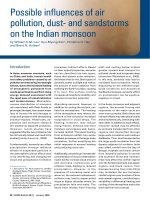
25.5 Nozzles installed at an angle
When installed at an angle, nozzles shall be aimed
at a point measured from the near side of the area
protected by the nozzle, the location of which is
calculated by multiplying the fractional aiming
factor in Table 5 by the width of the area protected
by the nozzle (see Figure 1).
Table 5 — Aiming factors for nozzles installed
at an angle (based on 150mm freeboard)
Discharge angle
a
Aiming factor
45° to 60° 0.25
60° to 75° 0.25 to 0.375
75° to 90° 0.375 to 0.5
90° (perpendicular) 0.5(centre)
a
Degrees from plane of hazard surface.
Licensed copy:RMJM, 30/08/2005, Uncontrolled Copy, © BSI
BS 5306-4:1986
© BSI 01-1999
15
Figure 1 — Aiming position for angled discharge nozzles
Licensed copy:RMJM, 30/08/2005, Uncontrolled Copy, © BSI
BS5306-4:1986
16
© BSI 01-1999
Section 6. Manual hose reel systems
26 Uses and general design
Manual hose reel systems shall comply with
section1, except as varied in this section.
COMMENTARY AND RECOMMENDATIONS ON CLAUSE 26.
Manual hose reel systems may be used to combat
fires in all hazards covered under 3.1, except those
that are inaccessible and beyond the scope of manual
fire fighting.
Manual hose reel systems may be used to supplement
fixed fire protection systems or portable fire
extinguishers for the protection of specific hazards
for which carbon dioxide is suitable. These systems
should not be used as a substitute for other fixed
carbon dioxide fire extinguishing systems with fixed
nozzles, except where the hazard cannot adequately
or economically be provided with fixed protection.
The decision as to whether hose reels are applicable
to the particular hazard should rest upon the
authority having jurisdiction.
Manual hose reels should be supplied with carbon
dioxide from containers located close to and
preferably adjacent to the hose stowage. Pipe runs
should be as short as possible to reduce frictional
losses which decrease the effectiveness of the carbon
dioxide discharge.
Where manual hose reels are installed in addition to
fixed fire protection systems, the carbon dioxide
supply for the manual hose reel should be in
addition to the quantity supplying the fixed fire
protection system.
27 Hazard to personnel
Where the discharge of a manual hose reel system
may lead to personnel being exposed to high
concentrations of carbon dioxide the safety
precautions of clause 34 shall be applied.
COMMENTARY AND RECOMMENDATIONS ON CLAUSE 27.
As pointed out in 3.2, the discharge of large amounts
of carbon dioxide to fight fire may create a hazard to
personnel. The quantity of carbon dioxide that will
be discharged, related to the volume and geometry of
the total enclosure, should be taken into account. If it
is considered that the developed concentration of
carbon dioxide could be hazardous to personnel, the
safety precautions set out in clause 34 should be
applied, and personnel escape routes should also be
considered.
28 Location and spacing of manual
hose reels
28.1 Manual hose reels shall be located where they
will be accessible during a fire and within reach of
the protected hazards. Actuating controls shall be
located at the hose reel station. Reels shall be ready
for immediate use.
28.2 If multiple hose reel stations are used, they
shall be so spaced that any area within the hazard
is covered by one or more hose reels.
29 Rate and duration of discharge
29.1 General
The rate and duration of discharge and
consequently the amount of carbon dioxide shall be
determined by the type and potential size of the
hazard. A manual hose reel system shall have
sufficient quantity of carbon dioxide to permit its
effective (liquid phase) use for at least 1min.
29.2 Simultaneous use of hose reels
Where simultaneous use of two or more hose lines is
possible, a sufficient quantity of carbon dioxide shall
be available to supply the maximum number of
nozzles that are likely to be used at any one time for
at least 1min.
30 Equipment design
30.1 Hose
Hose reels on systems with high pressure supply
shall be designed in accordance with BS4586 for a
working pressure of 190bar. Hose reels on systems
with a low pressure supply shall operate safely at a
working pressure of 27bar.
30.2 Discharge nozzle assembly
Hose reels shall be equipped with a discharge nozzle
assembly intended for use by one person. This shall
incorporate a quick opening shut-off valve to control
the flow of carbon dioxide through the nozzle and a
suitable handle, which shall be insulated, for
directing the discharge.
COMMENTARY AND RECOMMENDATIONS ON30.2. For
ease of manipulation the discharge nozzle assembly
should be attached to the hose by a swivel connection.
30.3 Hose storage
The hose shall be coiled on a reel or rack in such a
way that it will be ready for immediate use without
the necessity of coupling and such that it may be
uncoiled freely and without snags. If installed
outdoors it shall be protected against the weather.
Licensed copy:RMJM, 30/08/2005, Uncontrolled Copy, © BSI
BS 5306-4:1986
© BSI 01-1999
17
31 Charging the hose reel
All controls for actuating the system shall be located
in the immediate vicinity of the hose reel storage.
NOTEExcept when the hose line is in actual use, pressure
should not be permitted to remain in the system.
COMMENTARY AND RECOMMENDATIONS ON CLAUSE 31.
Operation of manual hose reel systems depends upon
manual actuation and manual manipulation of a
discharge nozzle. Speed and simplicity of operation
is, therefore, essential for successful extinction.
Licensed copy:RMJM, 30/08/2005, Uncontrolled Copy, © BSI
BS5306-4:1986
18
© BSI 01-1999
Section 7. System engineering design
32 System components
Principal components shall comply with the
appropriate British Standard and be installed in
accordance with the requirements of this standard.
All devices shall be designed for the service they will
encounter and shall not be readily rendered
inoperative or susceptible to accidental operation.
Devices shall normally be designed to function
properly from–30°C to 55°C or shall be marked to
indicate their temperature limitations.
Where the pressure of a permanent gas from pilot
containers is used as a means of releasing the
remaining containers, the supply and discharge rate
shall be designed for releasing all of the remaining
containers. The pilot gas supply shall be
continuously monitored and a fault alarm given in
the event of excessive pressure loss.
Where the pressure of a liquefied gas is used as a
means of releasing the remaining containers,
duplicate containers each of which is capable of
operating the system shall be used.
COMMENTARY AND RECOMMENDATIONS ON CLAUSE 32.
Various operating devices are necessary to control
the flow of the extinguishing agent to operate the
associated equipment. These include container
valves, distribution valves, automatic and manual
controls, delay devices, pressure trips and switches
and discharge nozzles.
All devices, especially those having external moving
parts, should be so located, installed or suitably
protected that they are not subject to mechanical,
chemical or other damage that would render them
inoperable.
33 System operation
33.1 Manual control
The manual control shall cause the complete system
to operate in its intended fashion.
The design of the manual control point shall be such
that it cannot be confused with a standard fire
alarm point.
In the event of the manual control point becoming
inoperative, emergency manual operation of
individual system components shall be possible.
Each manual control shall be prominently labelled
to identify the hazard protected (see Figure 2).
Manual controls shall not require a pull of more
than 150N or a movement of more than 300mm to
effect operation.
Manual controls shall be protected from inadvertent
operation as specified in 34.2.1.
Manual operation shall cause the system alarm and
the house fire alarm to operate.
COMMENTARY AND RECOMMENDATIONS ON33.1.
Manual controls should be located so as to be
conveniently and easily accessible at all times,
including the time of fire, and should preferably be
outside the protected space.
Emergency manual operation of individual system
components is usually by manual direct operation of
the device to be operated.
33.2 Automatic operation
33.2.1 Automatic systems shall be controlled by
appropriate automatic fire detection and release
devices selected according to the requirements of
the particular hazard.
COMMENTARY AND RECOMMENDATIONS ON33.2.1.
Electrically, pneumatically or mechanically
operated devices may be used. There is at the
moment no British Standard for pneumatically or
mechanically operated devices or their associated
control devices.
33.2.2 Electrically operated devices shall comply
with BS5839.
The power supply shall be independent of the supply
for the hazardous area. Where this is not
practicable, fluidic or mechanical devices shall be
used, or the system shall be provided with
emergency secondary power supplies with
automatic changeover in case the primary supply
fails.
33.2.3 Where two or more rapid response fire
detectors, such as those for detecting smoke or flame
are used, the system shall be designed to operate
only after two separate fire signals have been
initiated.
33.2.4 Automatic operation shall cause the system
alarm and the house fire alarm to operate.
34 Safety precautions
34.1 General
Suitable safeguards shall be provided to protect
persons in areas where the atmosphere may be
made hazardous by the leakage or discharge, either
planned or accidental, of carbon dioxide from a fire
extinguishing system.
34.2 Total flooding systems
34.2.1 Areas normally occupied. The automatic
discharge of the system shall be prevented by means
of an automatic/manual or manual only changeover
device when persons are or may be present within
the protected space or any adjacent area that could
be rendered hazardous by discharge of the gas.
Provision shall be made for the manual operation of
the fire extinguishing system by means of a control
situated outside the protected space or adjacent to
the main exit from the space.
Licensed copy:RMJM, 30/08/2005, Uncontrolled Copy, © BSI
BS 5306-4:1986
© BSI 01-1999
19
While the connection between the fire detection
system and the gas release is interrupted, the
operation of the fire detector shall activate the fire
alarm.
In order to guard against accidental release of the
gas from the storage containers, the supply of
carbon dioxide shall be isolated by means of a
monitored, normally closed valve in the feed line,
which will open only on a signal from the detection
system or manual release system.
The manual release push button or pull handle shall
be housed in a box and protected by a glass front or
other quick access front which can be broken
manually to gain access to the button or handle.
COMMENTARY AND RECOMMENDATIONS ON34.2.1.
Entry into a protected space should normally only be
made when the total flooding system has been placed
under manual control.
The system should be returned to fully automatic
control only when all persons have left the space.
For greater protection the manual release could be
key-operated with the operating key being retained in
an adjacent frangible glass or other quick access
fronted box.
34.2.2 Areas not normally occupied but which may
be entered. One of the following shall be provided to
prevent the automatic release of carbon dioxide
when the area has been entered by personnel:
a) an automatic/manual or manual only
changeover device that renders the system
capable of manual operation only; or
b) a manual stop valve sited in the supply line
from the storage vessel(s).
NOTEOption a) is preferred.
COMMENTARY AND RECOMMENDATIONS ON 34.2.2.
During periods of entry, the automatic discharge of
carbon dioxide, however brief, should be prevented.
The system should be returned to automatic control
as soon as all persons have left the space.
34.3 Local application systems
When unusual circumstances make it impossible for
personnel to leave the space protected by asystem
within the period of the pre-discharge alarm,
e.g.during difficult maintenance work, the
automatic operation of the system shall be
prevented as in34.2.1.
COMMENTARY AND RECOMMENDATIONS ON34.3. A
local application system normally presents a lower
risk to personnel than a total flooding system since
the final developed concentration of extinguishant
throughout the space will be lower. However, during
the period of discharge it is necessary to produce an
extinguishing concentration of gas around the
protected area with a risk of high local
concentrations. There is a further risk of higher
concentrations of gas occurring in pits, wells, shaft
bottoms and similar low areas.
The system may normally be on automatic control if,
after considering the geometry of the area in which a
local application system is used, it can be established
that there is not a foreseeable risk of a hazardous
concentration of carbon dioxide being produced in
any occupied part.
In assessing the degree of risk to personnel of
automatically controlled systems, the need to
approach close to the point of discharge or to work
within the confines of the protected area should be
considered. If it is necessary for personnel to work
within an area that is likely to be quickly enveloped
with CO
2
gas, consideration should be given to
providing a pre-discharge alarm that gives sufficient
warning to allow personnel to move away from the
protected area before CO
2
is released.
34.4 Additional requirements for all systems
34.4.1 Manifold venting. In systems using stop
valves (accidental) release of the carbon dioxide
from the storage containers shall activate a device
which gives visual warning to indicate that
carbondioxide has been released and is trapped in
the manifold.
In addition to the pressure relief device specified
in41.6 a manually operated vent valve shall be
fitted to the manifold so that the trapped
carbondioxide can be safely vented to atmosphere.
The vent valve shall normally be kept in the locked
shut position.
34.4.2 Discharge prevention during maintenance. To
enable system inspection and servicing to be carried
out in safety and also during times when the
protected area is undergoing alterations or
extensive maintenance, a device shall be provided to
prevent the discharge of carbon dioxide from the
storage containers.
Licensed copy:RMJM, 30/08/2005, Uncontrolled Copy, © BSI