BS 5588 4 1998 fire precautions in the design, construction and use of buildings
Bạn đang xem bản rút gọn của tài liệu. Xem và tải ngay bản đầy đủ của tài liệu tại đây (2.05 MB, 80 trang )
BRITISH STANDARD
BS 5588-4:1998
Incorporating
Amendments
Nos. 1 and 2, and
Corrigendum No. 1
Fire precautions in the
design, construction
and use of buildings —
Part 4: Code of practice for smoke
control using pressure differentials
ICS 13.220.20; 91.040.01
12&23<,1*:,7+287%6,3(50,66,21(;&(37$63(50,77('%<&23<5,*+7/$:
BS 5588-4:1998
This British Standard, having
been prepared under the
direction of the Management
Systems Sector Board, was
published under the authority
of the Standards Board and
comes into effect on
15 March 1998
© BSI 8 December 2004
First published June 1978
Second edition March 1998
The following BSI references
relate to the work on this
British Standard:
Committee reference FSH/14
Draft for comment 92/39700 DC
ISBN 0 580 26246 4
Committees responsible for this
British Standard
The preparation of this British Standard was entrusted to Technical
Committee FSH/14, Fire precautions in buildings, upon which the following
bodies were represented:
British Gas plc
British Retail Consortium
British Standards Society
British Telecommunications plc
Chartered Institution of Building Services Engineers
Chief and Assistant Chief Fire Officers’ Association
Consumer Policy Committee of BSI
Department for Education
Department of Health
Department of the Environment (Building Research Establishment)
Department of the Environment (Property and Buildings Directorate)
Department of the Environment for Northern Ireland
District Surveyors’ Association
Electricity Association
Fire Brigades Union
Health and Safety Executive
Home Office
Institute of Building Control
Institution of Gas Engineers
Institution of Structural Engineers
London Fire and Civil Defence Authority
Loss Prevention Council
National Association of Fire Officers
National Council of Building Material Producers
Royal Institute of British Architects
Scottish Office (Building Directorate)
Timber Research and Development Association
The following bodies were also represented in the drafting of the standard,
through subcommittees and panels:
Access Committee for England
Association of Building Engineers
Association of Consulting Engineers
British Automatic Sprinkler Association
British Council of Shopping Centres
British Fire Protection Systems Association Ltd.
British Fire Services’ Association
British Property Federation
Building Services Research and Information Association
Flat Glass Manufacturers’ Association
Hevac Association
Institute of Fire Safety
Institution of Fire Engineers
Intumescent Fire Seals Association
Nationwide Fire Services
Steel Window Association
Warrington Fire Research Centre
Amendments issued since publication
Amd. No. Date Comments
10019
Corrigendum. No. 1
April 1998 Unit corrected
13868 4 December 2002 See national foreword
14989 8 December 2004 See national foreword
BS 5588-4:1998
© BSI 8 December 2004
i
Contents
Page
Committees responsible Inside front cover
Foreword iii
Introduction 1
1Scope 1
2 References 1
3 Definitions 1
4 Analysis of the problem 6
5 System classification 8
6 Equipment 17
7 Actuation of pressure differential system 20
8 Electrical installations 21
9 Smoke control using pressure differentials 23
10 Design procedures 47
11 Installation and commissioning 49
12 Testing and maintenance 51
13 Documentation 52
14 Design calculations 52
Annex A (normative) Smoke control using pressure differentials in
atrium buildings 62
Annex B (normative) Test method for measuring the opening force at a
door 63
Annex C (normative) Interaction of pressure differential systems with
normal HVAC installations 64
Annex D (informative) Air leakage data 66
Annex E (normative) Test method for measuring the pressure differentials
under closed door conditions 68
Annex F (normative) Test method for measuring air velocities 68
Annex G (informative) Possible solutions for inability to obtain design
pressure differential 69
Annex H (informative) Design calculations requirements 70
List of references 72
Figure 1 — Design conditions for class A systems 9
Figure 2 — Design conditions for class B systems 11
Figure 3 — Design conditions for class C systems 13
Figure 4 — Design conditions for class D systems 15
Figure 5 — Design conditions for class E systems 17
Figure 6 — Pressure differences at an internal door 25
Figure 7a — Principles of a typical stair pressure differential system for
means of escape 29
Figure 7b — Principles of a typical stair pressure differential system for a
firefighting shaft 31
Figure 8 — Airflow patterns for pressure differential systems 34
Figure 9 — Stair pressure differential system configurations 37
Figure 10 — Pressurization of refuges and central control rooms 40
Figure 11 — Features of a depressurization system 42
Figure 12 — Configuration of zoned smoke control system 44
Figure 13 — Leakage paths in series 55
Figure 14 — Leakage paths in parallel 55
Figure 15 — Combination of series and parallel leakage paths 56
BS 5588-4:1998
ii
© BSI 8 December 2004
Page
Table 1 — Classification of buildings for smoke control using pressure
differentials 8
Table 2 — Minimum pressure differentials between specified areas for
class B systems 10
Table 3 — Minimum pressure differentials for class C systems 12
Table 4 — Minimum pressure differentials for class D systems 14
Table 5 — Minimum pressure differentials for class E systems 16
Table 6 — Minimum temperature/time design criteria for fans and HVAC
ductwork used for air/smoke release 19
Table 7 — Provision of stand-by pressure differential system equipment 19
Table 8 — Frequency of maintenance and functional testing of pressure
differential system plant 52
Table 9 — Airflow velocities through gaps and large openings 53
Table 10 — Values of K 59
Table D.1 — Air leakage data for doors 66
Table D.2 — Air leakage data for windows 67
Table D.3 — Air leakage data for walls and floors 67
BS 5588-4:1998
© BSI 8 December 2004
iii
Foreword
This code of practice was prepared under the direction of Technical Committee
FSH/14. It supersedes BS 5588-4:1978, which is withdrawn.
The start and finish of text introduced or altered by amendment is indicated
in the text by tags !". Tags indicating changes to text carry the number of
the amendment. For example, text altered by Amendment No. 1 is indicated
by !".
The other parts which comprise BS 5588 are as follows:
— Part 0: Guide to fire safety codes of practice for particular
premises/applications;
— Part 1: Code of practice for residential buildings;
— Part 5: Code of practice for firefighting stairs and lifts;
— Part 6: Code of practice for places of assembly;
— Part 7: Code of practice for the incorporation of atria in buildings;
— Part 8: Code of practice for means of escape for disabled people;
— Part 9: Code of practice for ventilation and air conditioning ductwork;
— Part 10: Code of practice for shopping complexes;
— Part 11: Code of practice for shops, offices, industrial, storage and other
similar buildings;
— Part 12: Managing fire safety.
It has been assumed in the drafting of this code that the execution of its
provisions will be entrusted to appropriately qualified and experienced people.
As a code of practice, this British Standard takes the form of guidance and
recommendations. It should not be quoted as if it were a specification and
particular care should be taken to ensure that claims of compliance are not
misleading.
This publication does not purport to include all the necessary provisions of a
contract. Users are responsible for its correct application.
Compliance with a British Standard does not of itself confer immunity
from legal obligations.
Summary of pages
This document comprises a front cover, an inside front cover, pages i to iv,
pages 1 to 73 and a back cover.
The BSI copyright notice displayed in this document indicates when the
document was last issued.
iv
blank
BS 5588-4:1998
© BSI 8 December 2004
1
Introduction
The pressure differential systems referred to in this standard are primarily intended for life safety and
firefighting purposes with the objective of maintaining tenable conditions in protected escape routes,
refuges, firefighting shafts, lobbies, etc. The general principles presented in this standard may also be
applied in situations where the primary aim is to prevent contamination by smoke, of goods or equipment
in rooms adjacent to a fire-affected space.
Guidance is given on the design of systems intended either to maintain a positive pressure within protected
spaces (pressurization) or to remove hot gases from the fire zone so as to maintain it at a lower pressure
than the adjacent protected space (depressurization).
Pressure differential systems provide one means of improving the level of fire safety within a building.
A decision as to whether such a system is appropriate to a particular project should be taken in context
with the overall design strategy for means of escape, firefighting and property protection within the
building.
This standard presents the general principles to be adopted in the design of various types of pressure
differential system. However, circumstances vary from building to building and it is not possible to cover
every situation here, although it may be possible to design an effective system for other applications using
the principles of this standard.
1 Scope
This part of BS 5588 gives guidance on the design, installation, testing and maintenance in new and
existing buildings of systems intended to limit the spread of smoke by means of pressure differentials.
However, this standard does not cover smoke ventilation systems used in theatres and other places of
assembly which protect the auditorium from a fire in the stage area by creating a pressure differential
between the stage and the auditorium.
2 References
2.1 Normative references
This part of BS 5588 incorporates, by dated or undated reference, provisions from other publications. These
normative references are made at the appropriate places in the text and the cited publications are listed on
page 72. For dated references, only the edition cited applies; any subsequent amendments to, or revisions
of the cited publication apply to this part of BS 5588 only when incorporated in the reference by
amendment or revision. For undated references, the latest edition of the cited publication applies, together
with any amendments.
2.2 Informative references
This part of BS 5588 refers to other publications that provide information or guidance. Editions of these
publications current at the time of issue of this standard are listed on page 73, but reference should be made
to the latest editions.
3 Definitions
For the purposes of this British Standard the following definitions apply.
3.1
accommodation area
area of a building where the main work function of the building is carried out
3.2
air release
means by which pressurizing air is able to escape from the accommodation area or other unpressurized
space to external air
3.3
atrium
space within a building, not necessarily vertically aligned, passing through one or more structural floors
NOTE Enclosed lift wells, escalator wells, building services ducts and stairways are not classified as atria.
BS 5588-4:1998
2
© BSI 8 December 2004
3.4
basement
storey with a floor that is at some point more than 1.2 m below the highest level of ground adjacent to the
outside walls
3.5
controlled fire load
fire load that is limited by means of management controls on the quantities of combustible material that
are present on the atrium base or where the fire load is limited by an effective automatic suppression
system
3.6
dedicated system
pressure differential system that does not share components with any other system
3.7
depressurization
smoke control using pressure differentials where the air pressure in adjacent spaces is reduced to below
that in the protected space
3.8
depressurized space
part of a building from which air and smoke are extracted for the purposes of depressurization
3.9
depth (of a building)
distance to the surface of the lowest point of the floor of the lowest storey, measured at the centre of that
face of the building where the measurement is greatest from the level of the footway or paving in front of
that face, or if there is no such footway or paving, from the level of the ground
3.10
escape route
route forming part of the means of escape from any point in the building to a final exit
3.11
evacuation lift
lift that may be used for the evacuation of disabled people in an emergency
3.12
final exit
termination of an escape route from a building giving direct access to a street, passageway, walkway or
other open space sited to ensure the rapid dispersal of persons from the vicinity of a building so that they
are no longer in danger from fire and/or smoke
3.13
fire compartment
building or part of a building, comprising one or more rooms, spaces or storeys, constructed to prevent the
spread of fire to or from another part of the same building, or to an adjoining building
3.14
fire detection zone
sub-division of the building such that the detection of a fire within it will be indicated by the fire alarm
system separately from an indication of fire in any other sub-division
3.15
fire resistance
ability of a component or construction of a building to satisfy for a period of time some or all of the
appropriate criteria specified in the relevant part of BS 476
BS 5588-4:1998
© BSI 8 December 2004
3
3.16
fire zone
room or compartment in which the fire is assumed to occur for the purposes of design of pressure
differential systems
3.17
firefighting lift
lift designated to have additional protection for firefighting use, directly controllable by the fire service
when fighting a fire
3.18
firefighting lobby
protected lobby providing access from a firefighting stair to the accommodation area and to any associated
firefighting lift
3.19
firefighting shaft
protected enclosure containing a firefighting stair, firefighting lobbies and, if provided, a firefighting lift
together with its machine room
3.20
firefighting stair
protected stairway communicating with the accommodation area only through a firefighting lobby
3.21
height
for buildings, the distance to the surface from the highest point of the floor of the highest storey (excluding
any such storey consisting exclusively of plant rooms), measured at the centre of that face of the building
where the measurement is greatest to the level of the footway or paving in front of that face, or if there is
no such footway or paving, to the level of the ground
3.22
HVAC
heating, ventilation and/or air conditioning
3.23
inherent leakage paths
gaps or cracks in the construction or around doors and windows etc. which provide a path for air to flow
between the pressurized/depressurized space and the external air
3.24
lift well
space in which the lift and the counterweight (if any) move. This space is materially enclosed by the bottom
of the pit, the vertical walls and the ceiling
3.25
means of escape
structural means whereby a safe route is provided for persons to travel from any point in a building to a
place of safety
3.26
neutral pressure plane
point in a building where the internal air pressure due to wind and stack effects is equal to the external
ambient pressure
3.27
non-dedicated system
pressure differential system that shares components with another system, such as an HVAC system
3.28
over-pressure relief
provision for releasing excess pressurizing air from the pressurized space
BS 5588-4:1998
4
© BSI 8 December 2004
3.29
phased evacuation
system of evacuation in which different parts of premises are evacuated in a controlled sequence. Those
parts of the building expected to be at greatest risk are evacuated first
3.30
place of safety
place in which persons are in no danger from the consequences of a fire within the building
3.31
pressurization
smoke control using pressure differentials, where the air pressure in the spaces being protected is raised
above that in the fire zone
3.32
pressure containment lobby
lobby provided at fire access level to reduce the loss of pressure from a stair due to a final exit door being
constantly open
3.33
pressure differential system
system of fans, ducts and vents provided for the purpose of creating a pressure differential between the fire
zone and the protected space
3.34
pressurized space
shaft, lobby, corridor or other compartment in which the air pressure is maintained at a higher value than
that of the fire zone
3.35
protected corridor
circulation area consisting of a corridor enclosed with fire-resisting construction (other than any part that
is an external wall of a building)
3.36
protected escape route
escape route having an adequate degree of fire protection
3.37
protected lobby
circulation area consisting of a lobby enclosed with fire-resisting construction (other than any part that is
an external wall of a building)
3.38
protected space
fire-resisting shaft or compartment within a building which is protected against the ingress of smoke by a
pressure differential system
3.39
protected stairway
stair discharging through a final exit to a place of safety (including any exit passageway between the foot
of the stair and the final exit) that is adequately enclosed with fire-resisting construction
3.40
refuge
area that is both separated from a fire by fire-resisting construction and provided with a safe route to a
storey exit, thus constituting a temporarily safe space for disabled persons to await assistance for their
evacuation
BS 5588-4:1998
© BSI 8 December 2004
5
3.41
simple lobby
lobby that does not give direct access to lifts, shafts or ducts that could constitute a significant leakage path
for smoke to spread to other storeys within the building. A simple lobby may be either unventilated or
naturally ventilated
NOTE A lobby connected to a lift well or other shaft is still a simple lobby if all such shafts are pressurized.
3.42
single-pressure system
pressure differential system in which the air supply to a pressurized space or extraction from a
depressurized space is designed to operate only in an emergency
3.43
single-stage system
pressure differential system designed to work only in an emergency
3.44
smoke control
technique for influencing the production, movement or removal of smoke from a building in order to protect
the means of escape, contents or structure, and/or to assist firefighting operations
3.45
smoke control zone
sub-division of a building for smoke control purposes
3.46
smoke damper
mechanical device that when closed prevents smoke passing through an aperture within a duct or
structure. The device may be open or closed in its normal position and may be automatically or manually
actuated
3.47
smoke shaft
enclosed space in a building provided for venting smoke from a firefighting stair or one or more firefighting
lobbies or other protected areas
3.48
stack effect
pressure differential resulting from the differences in density of two interconnected columns of air at
different temperatures, one inside the building at the internal ambient temperature, and the other outside
the building at the external ambient temperature
3.49
storey exit
final exit (see 3.12), or a doorway giving direct access to a protected stairway, protected lobby or external
escape route
3.50
two-pressure system
pressure differential system in which a continuous low level of operation is provided as part of the normal
ventilation system, with provision for increasing the pressure differential in an emergency
3.51
two-stage system
pressure differential system designed to provide a low level of ventilation normally and is brought into full
operation in an emergency
3.52
vent
window, roof-light, door, louvre, grille or other ventilating device either open or capable of being opened to
permit the passage of air between a part of the building and the external air
BS 5588-4:1998
6
© BSI 8 December 2004
3.53
zoned smoke control
system that combines depressurization of the fire zone and pressurization for all contiguous spaces
requiring protection
4 Analysis of the problem
4.1 General
The purpose of a pressure differential system, whether used for the protection of means of escape, property
or for firefighting operations, can have a significant influence on the system design and specification. It is
therefore essential that the fire safety objectives are clearly established and agreed with the appropriate
approval bodies at an early stage in the design process.
The need for smoke control and the type of system chosen should not be considered in isolation but as an
integral part of the total package of fire safety measures for the building, e.g. means of escape, firefighting
facilities, degree of compartmentation.
The acceptability of any system depends ultimately on whether the necessary pressure differential levels
and airflow rates are achieved (see Clause 12 #and BS 5588-12$).
NOTE 1 Guidance on the means of calculating the air supply rate for these levels and rates is given in Clause 14. However, provided
that the appropriate functional objectives [see items a), b) and c) below] are met, the designer may choose to use other calculation
procedures if these are appropriate to the specific case.
The main objectives addressed in this standard are as follows.
a) Occupant safety. It is essential that tenable conditions are maintained in protected escape routes and
refuges for as long as they are likely to be in use by the building occupants.
b) Firefighting. To enable firefighting operations to proceed efficiently, firefighting shafts should be
maintained essentially free of smoke so that access to the fire-affected storey can be achieved without the
use of breathing apparatus. The pressure differential system should be designed so as to limit the spread
of smoke from the lobby into the protected shaft under normal firefighting conditions.
c) Property protection. The spread of smoke into sensitive areas such as those containing valuable
equipment, data processing facilities and other items that are particularly sensitive to smoke damage
should be limited.
NOTE 2 A pressure differential system may be used for property protection. The procedures for occupant safety detailed in this
standard are generally appropriate to the protection of such sensitive items. However, it may be desirable first to investigate the
sensitivity to smoke damage of the individual items of concern and to ensure that the system design provides an adequate pressure
differential and sufficient dispersal of any stray smoke in order to maintain smoke concentrations within acceptable limits.
4.2 Smoke movement in the building
In the event of fire, the smoke produced follows a pattern of movement arising from the following main
driving forces.
a) Buoyancy experienced by hot gases on the fire storey. Within the fire zone smoke produced by the fire
experiences a buoyancy force owing to its reduced density. In a building this can result in an upwards
smoke movement between storeys if leakage paths exist to the storey above. In addition, this buoyancy
can cause smoke to spread through leakage paths in vertical barriers between rooms, e.g. doors, walls,
partitions. The pressure differential typically causes smoke and hot gases to leak out of gaps at the top
of a door and cool air to be drawn in through gaps at the bottom.
b) Thermal expansion of hot gases in the fire zone. Fire-induced expansion of gases can result in a build-up
of pressure, accompanied by a flow of hot gases out of the compartment. However, in most cases the
initial expansion forces may be ignored.
c) Stack effect throughout the building. In winter the air in a building is generally warmer and less dense
than the external air. The buoyancy of the warm air causes it to rise within vertical shafts in the building,
and a pressure gradient is set up in the column such that cold air is drawn into the bottom of the shaft
and warm air is forced out at the top. In summer, when the air inside the building can be cooler than that
outside, the reverse condition may exist, i.e. air is forced out at the bottom of the stack and drawn in at
the top. In either case, at some intermediate point a neutral plane is formed where the pressures of the
external and the internal air are equal.
BS 5588-4:1998
© BSI 8 December 2004
7
d) Wind pressure forces. When wind blows against the side of a building, it is slowed down, resulting in
a build-up of pressure on the windward face. At the same time the wind is deflected and accelerated
around the side walls and over the roof, creating an eddy on the leeward side of the building and a
consequent reduction in pressure, i.e. suction in these areas. The greater the speed of the wind, the
greater the suction. The main effect of these pressures is to produce a horizontal movement of air through
the building from the windward to the leeward side. If the building is tightly constructed this effect will
be slight. However, if the building is loosely constructed, i.e. with openable doors and windows, then the
effect will be more pronounced. For example, in a fire, if a broken window exists on the windward side of
the building, the wind can force the smoke through the building horizontally or in some circumstances
vertically. It is difficult to predict accurately the wind pressures that will be exerted on buildings or the
resultant internal airflows, and computer (see 9.1.5) or wind tunnel analysis may be necessary for a full
understanding.
NOTE Guidance on wind loadings is given in CP 3:Chapter V:Part 2 or BS 6399-2.
e) HVAC systems. HVAC systems can supply air to the fire zone and aid combustion or transport smoke
rapidly to areas not within the fire zone and should generally be shut down in the event of fire. However,
such systems can often be modified to assist in restricting smoke spread or be used in conjunction with
pressure differential system air supply and/or release systems.
4.3 Methods of smoke control
4.3.1 General
The effect of the air movement forces described in 4.2 is to create pressure differentials across the
partitions, walls, floors and doors that can cause smoke to spread to areas removed from the fire source.
The techniques most commonly used to limit the degree of spread are listed below.
a) Smoke containment using a system of physical barriers, e.g. walls and doors, etc., to inhibit the spread
of smoky gases from the fire-affected space to other parts of the building.
b) Smoke clearance, using any method of assisting the fire service in removing smoky gases from a
building when smoke is no longer being produced, i.e. after extinction.
c) Smoke dilution; deliberately mixing the smoky gases with sufficient clean air to reduce the hazard
potential.
d) Smoke (and heat) exhaust ventilation, using any method to achieve a stable vertical separation
between the warm smoky gases forming a layer under the ceiling and those lower parts of the same space
requiring protection from the effects of smoke for evacuation of occupants and firefighting operations. For
example, the continuous exhaust of smoke using either natural or powered ventilators, and the
introduction of clean replacement air into the fire-affected space.
e) Pressurization. (See 3.31.)
f) Depressurization. (See 3.7.)
g) Zoned smoke control. (See 3.53.)
NOTE This standard provides guidance and information on smoke control using pressure differentials, i.e. only the techniques given
in items e), f) and g).
4.3.2 Pressure differentials versus other forms of smoke control
A combination of containment and extraction/venting is usually used as smoke control in large undivided
spaces, e.g. shopping malls, atria, warehouses etc. Smoke produced by the fire is allowed to flow under its
own buoyancy toward smoke reservoirs above the occupied space. Powered extraction systems or natural
vents assist in the containment process by removing smoke from the reservoir and thus maintain the base
of the smoke layer at a safe height. However, the entrainment of air into the smoke plume can produce a
large volume of hot smoky gases, even from a modest fire, and high extraction rates are generally required.
Smoke clearance systems are generally intended for clearing smoke in the aftermath of a fire and are
therefore generally unsuitable for meeting the functional objectives listed in 4.1.
Smoke dilution systems work on the principle of supplying and exhausting large quantities of air from the
fire zone. They do not control the movement of smoke, but instead rely on diluting the smoke to such a level
that the vision and breathing of occupants in that space are not critically affected.
Smoke control using pressure differentials generally requires lower ventilation rates but is limited to the
protection of enclosed spaces adjacent to the fire.
BS 5588-4:1998
8
© BSI 8 December 2004
5 System classification
5.1 General
Smoke control using pressure differentials can be implemented in several different types of buildings, with
differing requirements and design conditions.
For the purposes of this standard, the design conditions have been placed into five separate systems
(classes A, B, C, D and E) and are detailed in Table 1.
Systems for atrium buildings are not covered within this standard, but the recommendations given in
Annex A should be followed.
Table 1 — Classification of buildings for smoke control using pressure differentials
NOTE 1 The system classes listed above are not exhaustive.
NOTE 2 Attention is drawn to the Building Regulations 1991 [1] regarding means of escape and firefighting, and to the
recommendations in the relevant parts of BS 5588.
5.2 Class A system
The design conditions for blocks of flats and maisonettes are based on the assumption that dwellings (other
than the dwelling of fire origin) are not evacuated unless directly threatened by fire.
NOTE 1 The class A system is not to be used if the flats form part of mixed use development.
!The level of fire compartmentation in blocks of flats and maisonettes at design stage is such that is
usually safe for the occupants to remain in their own dwellings during a fire. The prime objective of the
class A system is to maintain the staircase(s) free from smoke when there is a fire in a dwelling. The system
would offer equivalent or better arrangement for the protection of the staircase compared with natural
smoke ventilation systems. Therefore a class A system does not provide a form of smoke control to the front
entrance door of the flat/dwelling.
NOTE 2 Smoke seals should be provided to the flat front entrance doors.
NOTE 3 On projects where smoke control is required to the front entrance doors of the flats/dwellings, this situation is outside the
scope of a class A system, and therefore should be referred to a fire engineering solution.
NOTE 4 It is imperative that the designer of the system consults with the appropriate authority to establish the correct design
objective.
"
It is unlikely that more than one door onto the protected space (either between the stair and the
lobby/corridor or the final exit door) will be open simultaneously.
NOTE 5 Where there is three door protection between the protected stairway enclosure and the compartmented accommodation
area, the recommendation for open door airflow velocity as applicable to items a), b), c), d) and e) below does not apply.
The airflow through the doorway between the pressurized stair and the lobby or corridor should be not less
than 0.75 m/s when:
a) the door between the lobby/corridor and the pressurized stair is open on any one storey;
b) the air release from the lobby/corridor on that storey is open;
c) all doors between the pressurized stair and the lobbies/corridors are closed on all other storeys;
d) all doors between the pressurized stair and the final exit are closed; or
e) the final exit door is closed.
System class !Examples"
A Residential, sheltered housing and buildings designed for three door protection (see 5.2)
B Protection of firefighting shafts (see 5.3)
C Commercial premises (using simultaneous evacuation) (see 5.4)
D Hotels, hostels and institutional-type buildings, excluding buildings designed to meet
class A (see 5.5)
E Phased evacuation (see 5.6)
BS 5588-4:1998
© BSI 8 December 2004
9
The pressure difference across a closed door between the pressurized stair and the lobby/corridor should be
not less than 50 Pa ± 10 % when:
1) the air release from the lobby/corridor on that storey is open;
2) on all other storeys the doors between the pressurized stair and the lobby/corridor are closed;
3) all doors between the pressurized stair and the final exit are closed;
4) the final exit door is closed.
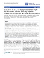
The above design conditions for class A systems are shown in Figure 1.
NOTE 6 Figure 1 can include lobbies.
!
"
5.3 Class B system
A pressure differential system can be used to minimize the potential for serious contamination of
firefighting stairs by smoke during fire service operations.
BS 5588-5 provides guidance on the general design and construction of firefighting stairs and lifts.
NOTE 1 During firefighting operations it is necessary to open the door between the firefighting lobby and the accommodation area
to deal with a fully developed fire.
It is common firefighting practice that the first crews arriving at an incident in a building with a
firefighting shaft obtain information about the floor involved and set up a bridgehead/forward control.
Airflow criterion (all doors closed)
Figure 1 — Design conditions for class A systems
Door open
0.75 m/s
50 Pa
Door closed
Relief
path
Relief
path
BS 5588-4:1998
10
© BSI 8 December 2004
Crews committed from forward control to attack the fire usually attempt to take hoselines uncharged to
the protected lobby on the fire-affected storey and connect to the riser outlet. However, if the lobby area on
the fire-affected storey is untenable, hoselines are connected to the riser on the floor below or, in the case
of basements, the floor above the fire-affected storey.
Where hoselines are connected to the riser on a floor other than the fire-affected storey, the hoselines can
prevent the closing of the doors between the lobby and stairs whilst firefighting operations are in progress.
This can cause smoke to enter the protected area.
The velocity of hot smoke and gases from a fully developed fire can reach 5 m/s. Although firefighting
operations, such as the use of a jet, can contribute significantly to the holding back of hot smoke and gases,
it is impractical to provide sufficient through-flow of air in order to prevent ingress of smoke into the
firefighting lobby.
It is, however, essential that the stair shaft is kept clear of serious smoke contamination. To limit the
spread of smoke from the fire zone to the lobby and thence into the stair an air velocity of at least 2 m·s
–1
through the open door between the firefighting lobby and the accommodation area should be provided.
To achieve the recommended flow of 2 m/s through the open stair door, sufficient leakage should be ensured
from the accommodation area to the exterior of the building. In the later stages of fire development more
than adequate leakage is generally provided by breakage of external glazing. However, it should not be
assumed that windows will have failed before the arrival of the fire service, and it is therefore essential to
ensure that sufficient leakage area is available, via the ventilation ductwork or specifically designed air
release paths.
The system should be designed to keep the firefighting stair and firefighting lobby and, where provided,
the firefighting lift well, clear of smoke. In the event of smoke entering the lobby, the pressure within the
stair should not drive smoke into the lift well or vice-versa. This should be achieved by providing separate
pressurization of the firefighting lift well, lobby and stair.
The fan/motor units for a firefighting lift well may be common with its associated stair, providing that:
a) the air is provided through separate ductwork;
b) the distribution of air to each duct is controlled so that sufficient air is provided to each space at all
times.
The air supply should be sufficient to maintain the pressure differential given in Table 2 when all doors to
the lift, stair and lobby, and the final exit doors are closed and the air release path from the accommodation
area is open.
Table 2 — Minimum pressure differentials between specified areas for class B systems
"
!
Specified area
Pressure differential to be
maintained
min
Across lift well and accommodation area with all doors closed
b
50 Pa ± 10 %
a
Across stairway and accommodation area with all doors closed
b
50 Pa ± 10 %
a
Across closed doors between each lobby and accommodation area with all
doors closed
bc
45 Pa ± 10 %
a
a
The ± is not to be used in designing the system, it is only there for flexibility when testing the system.
b
Air release path from the accommodation on the storey (fire floor) where the pressure difference being measured is open.
c
45 Pa is required to overcome wind pressure, fire pressure and stack effect components incorporating a safety margin.
Providing 45 Pa is the outcome, there are no restrictions on how it is achieved.
BS 5588-4:1998
© BSI 8 December 2004
11
The air supply should be sufficient to maintain an airflow of 2 m/s through the open door between the lobby
and the accommodation area at the fire-affected storey with all of the following doors open between:
1) the stair and the lobby on the fire-affected storey;
2) the stair and the lobby on the adjacent storey;
3) the firefighting lift well and the lobby;
4) the stair and the external air at the fire service access level;
5) the air release path from the accommodation area, on the storey on which the airflow is being
measured.
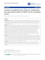
See Figure 2 for these design conditions.
NOTE 2 Where a class B system is used within a residential building, the air release path may be from the non-firefighting lobby
corridor on the storey where the airflow is being measured.
NOTE 3 Where a door has two leaves, one leaf (or the leaf with the least openable area where unequal size doors are provided) may
be assumed to be in the closed position for these calculations.
NOTE 4 If a pressure containment lobby is provided at fire service access level, for design purposes, the door indicated in item 4
above may be closed.
!The design of such pressure containment lobbies and their effect on pressure differential smoke control
systems should be justified on a case by case basis.
"
Any air supply system serving a firefighting shaft should be separate from any other ventilation or
pressure differential system.
The maximum force required to open any door within the escape route should in no circumstances
exceed 100 N, applied at the door handle.
NOTE 5 The corresponding maximum pressure differential across the door can be determined using the procedures in Annex B, as
a function of the door configuration.
!
"
Airflow criterion Pressure difference criterion (all doors closed)
Figure 2 — Design conditions for class B systems
2.0 m/s
50 Pa
45 Pa
Firefighting
stair
Firefighting
lobbies
Door open
Door closed
Door open
Door open
Air flow from
firefighting lift
shaft
Door open
(Firefighting
lobbies)
Firefighting
lobbies
Firefighting
stair
Relief
path
Door closed
(Firefighting
lobbies)
BS 5588-4:1998
12
© BSI 8 December 2004
5.4 Class C system
This classification applies to systems other than classes A, B or D using simultaneous evacuation and with
one of the following:
a) !with lobbies, no restrictions in height";
b) !without lobbies, a single stair up to 11 m and";
c) !without lobbies, more than one stair up to 18 m".
In the event of a simultaneous evacuation it is assumed that the stairways will be occupied for the nominal
period of the evacuation, and thereafter will be clear of evacuees. Consequently, the evacuation will occur
during the incipient stages of fire development, and some smoke leakage onto the stairway can be tolerated.
The airflow due to the pressurization system should clear the stairway of this smoke.
The occupants being evacuated are assumed to be alert and aware, and familiar with their surroundings,
thus minimizing the time they remain in the building.
The airflow through the doorway between the pressurized space and the accommodation area should be not
less than 0.75 m/s when:
1) the doors between the accommodation area and the pressurized stairway and any lobby on the fire
floor are open;
2) the air release path from the accommodation area on the storey where the airflow being measured is
open;
3) all other doors other than the fire floor doors are assumed to be closed.
The pressure difference across a closed door between the pressurized space and the accommodation area
should be as given in Table 3.
Table 3 — Minimum pressure differentials for class C systems
The design conditions for class C systems are shown in Figure 3.
NOTE Figure 3 can include lobbies.
Position of other doors
Pressure differentials to be
maintained
min
.
i) Doors between accommodation area and the pressurized space are
closed on all storeys
50 Pa ± 10 %
ii) All doors between the pressurized stair and the final exit are closed
iii) Air release path from the accommodation on the storey where the
pressure difference being measured is open
iv) Final exit door is closed
v) Final exit door is open and other items i) to iii) above 10 Pa
BS 5588-4:1998
© BSI 8 December 2004
13
!
"
5.5 Class D system
This classification applies to systems used in the following:
a) hotels, hostels and institutional-type buildings, excluding buildings designed to meet class A system
classification;
b) any building where a discounted stairway has not been provided because a pressure differential
system is installed;
c) any buildings more than 18 m high where the pressure differential system has been adopted in lieu of
the provision of lobbies (not including residential-type buildings or firefighting shafts).
Class D systems are appropriate in buildings where the occupants may be sleeping, e.g. hotels, hostels and
institutional-type buildings. The time for the occupants to move into a protected area prior to reaching the
final exit can be greater than that expected in an alert or able-bodied environment, and occupants may be
unfamiliar with the building or need assistance to reach the final exit/protected space.
Class D systems are also appropriate when the presence of a pressure differential system has served to
justify the absence of a discounted stairway and/or lobbies that would normally be required under the
appropriate building regulations (England and Wales, Scotland, Northern Ireland) [1].
NOTE Figure 3 can include lobbies.
Figure 3 — Design conditions for class C systems
0.75 m/s
10 Pa
50 Pa
Door open
Door closed
Relief
path
Relief
path
Relief
path
Door closed
Door
open
BS 5588-4:1998
14
© BSI 8 December 2004
The airflow through the doorway between the pressurized space and the accommodation area on the fire
floor should be not less than 0.75 m/s when:
1) the door between the accommodation area and the pressurized space on the fire storey is open;
2) all doors within the pressurized spaces on the fire floor to the final exit which cross the escape route
from the accommodation area are open;
3) all doors between the pressurized stair and the final exit are open;
4) the final exit door is open;
5) the air release from the accommodation area on the fire floor is open;
6) the doors on the other floors are closed.
The pressure difference across the closed door between the pressurized space and the accommodation area
on the fire storey should be as given in Table 4.
Table 4 — Minimum pressure differentials for class D systems
The design conditions for class D systems are shown in Figure 4.
NOTE Figure 4 can include lobbies.
Position of other doors
Pressure differential to be
maintained
min
.
Door between accommodation area and pressurized space on the fire
storey is closed
10 Pa
All doors within pressurized space that cross the escape route from the
accommodation area to the final exit door are open
All doors between the pressurized stair and the final exit door are open
The final exit door is open
The air release path from the accommodation area on the storey where the
pressure difference is being measured is open
The doors between the accommodation area and the pressurized space are
closed on all storeys
50 Pa ± 10 %
All doors between the pressurized stair and final exit door are closed
The air release path from the accommodation area on the storey where the
pressure difference being measured is open
The final exit door is closed
BS 5588-4:1998
© BSI 8 December 2004
15
Airflow criterion Pressure difference criterion Pressure difference criterion
(all doors closed)
NOTE Figure 4 can include lobbies.
Figure 4 — Design conditions for class D systems
0.75 m/s
10 Pa
50 Pa
Door open
Door
closed
Relief
path
Relief
path
Door open
Door
open
Door
open
Relief
path
Door
closed
Door
closed
BS 5588-4:1998
16
© BSI 8 December 2004
5.6 Class E system
This classification covers systems used in buildings with phased evacuation, and where the expected total
evacuation time exceeds 10 min. For design purposes, this represents the situation where the number of
evacuation stages is greater than three, using two floors at a time.
It is assumed that the building would still be occupied for a considerable time during phased evacuation
whilst the fire develops. The protected stairways should be maintained free of smoke to allow persons to
escape in safety from floors other than the fire floor at a later stage in the fire development.
The airflow through the doorway between the pressurized space and the accommodation area on the fire
floor should be not less than 0.75 m/s when:
a) the doors between the accommodation area and the pressurized space on the storey above the fire floor
are open;
b) all doors within the pressurized spaces on those two storeys that cross the escape route from the
accommodation area to the final exit are open;
c) all doors between the pressurized stair and the final exit are open;
d) the final exit door is open;
e) the air release from the accommodation area on the fire floor is open.
The pressure difference across the closed door between the pressurized space and the accommodation area
on the fire floor should be not less than as given in Table 5.
Table 5 — Minimum pressure differentials for class E systems
NOTE 1 See 9.2.2.2 regarding pressure gradient.
The design conditions for class E systems are shown in Figure 5.
NOTE 2 Figure 5 can include lobbies.
Position of other doors
Pressure differential to be
maintained
min
.
The doors between the accommodation area and the pressurized space are
open on two adjacent storeys
10 Pa
All doors within the pressurized space on those two storeys that cross the
escape route from the accommodation area to the final exit are open
All doors between the pressurized stair and the final exit are open
The final exit door is open
The air release path from the accommodation area on the storey where the
pressure difference being measured is open
The doors between the accommodation area and the pressurized stair on
all storeys are closed
50 Pa ± 10 %
All doors between the pressurized stair and the final exit are closed
The air release path from the accommodation area on the storey where the
pressure difference being measured is open
The final exit door is closed
BS 5588-4:1998
© BSI 8 December 2004
17
!
"
6 Equipment
6.1 General
The equipment needed to create a pressure differential between the protected space and the
accommodation area consists of:
a) fans and drive mechanisms;
b) air release provisions;
c) actuation systems;
d) over-pressure relief vents;
e) electrical power supplies (primary and secondary);
f) stand-by equipment;
g) distribution ductwork system.
Where a ventilation system (HVAC) is used to form part of the pressure differential system, the
components should conform to the recommendations of this clause.
To ensure that the system operates satisfactorily at all times in the event of an emergency there should be
provision for an alternative power supply and stand-by plant.
Installations should conform to BS 5720.
Airflow criterion Pressure difference criterion Pressure difference criterion
(all doors closed)
Figure 5 — Design conditions for class E systems
0.75 m/s
10 Pa
50 Pa
Door open
Relief
path
Door
closed
Relief
path
Relief
path
Door open
Door
closed
Door
open
Door
open
Door
closed
Door
open
Door
open
Door
closed
Door closed
BS 5588-4:1998
18
© BSI 8 December 2004
6.2 Fans and drive mechanism
The fan duty is calculated by summation of the leakage from all the identifiable leakage paths in the
pressurized zones. It is essential that the architect and builder agree with the installing engineer what is
expected from the escape route construction, e.g. gap size under doors, leakage through joints in the
construction and through the boundary of the pressurized space, so that the actual leakage closely matches
that of the design. The calculated leakage should then be increased by a factor (see below) to allow for
uncertainties in identified leakage paths.
A factor of 1.5 should be used where solid construction encloses the protected space. Where materials and
construction techniques that may produce significant leakage are used, e.g. plasterboard walls and false
ceilings, this factor of 1.5 may need to be increased, following consultation with the architect and builder.
Where there is doubt as to the air tightness of an existing building construction (particularly in the case of
a building refurbishment), and where refurbishment is taking place, it may be advisable to assess the
leakage areas using a calibrated portable fan prior to specifying the fan performance.
The ductwork should be sized according to the expected flow rate. The pressure loss in the ductwork and
through any dampers and registers should be used together with the required pressure in the protected
space to specify the fan performance.
When selecting a fan for the required duty, account should be taken of the temperature and time for which
the system is required to work. (See Table 6 for air release and depressurization systems.)
The fan duty should be assessed for the following.
a) Volume flow rate. The volume flow rate is the total air supply to or from all pressurizing or
depressurizing spaces served by the particular fans plus an allowance for unidentified leakage paths and
for probable ductwork leakage. The allowance for leakage to be added to the volume flow rate should
be 15 % for sheet metal ductwork and 25 % for builders’ ducts, unless an on-site test determines a lower
level of leakage.
b) Total fan pressure. This is the total resistance of the distribution system plus the emergency
pressurization level.
c) Static fan pressure. This is the fan total pressure minus the velocity head at the fan discharge.
d) !Text deleted"
To control the pressure differential, over-pressure release vents may need to be fitted in the pressurized
spaces. It is recommended that the pressure release vents are located at the top of each stair and should
open directly to the external air.
Where pressure differential fans serve more than one pressurized space concurrently, it may be necessary
to interpose high-pressure drop volume control dampers to ensure that when high leakage occurs from an
area, e.g. when doors are open or construction failure occurs, some protection continues in the remaining
areas.
6.3 Air release
It is essential that a low-resistance path to external air is provided in a pressurization/depressurization
system. By providing such a path from the accommodation area, the desired pressure differential between
the accommodation area and the protected space can be maintained, thus excluding smoke from the
protected space.
The methods of air release are:
a) external wall vents, which include automatically openable windows and trickle ventilators;
b) vertical shaft air release, where vents in accommodation area spaces connect to a common vertical
shaft which releases smoke at the top of the building;
c) mechanical extraction, which consists of fans and ductwork, either dedicated to the removal of
air/smoke from the spaces affected by fire or an HVAC system suitably equipped and controlled to fulfil
this function. !The fan should be suitable for continuous operation for the appropriate period of time
and temperature specified in Table 6."
Where the actuation of the air release system is automatic it should be controlled in such a way that it only
operates in the fire zones.
NOTE Arrangements for the control of a powered automatic air release system are given in Annex C.
BS 5588-4:1998
© BSI 8 December 2004
19
The air release system should be such that in normal operation or in the fail-safe mode there is no
movement of smoke between different fire compartments.
Where the air release is achieved by mechanical extraction the fans and ductwork should operate
continuously at the appropriate temperature and period of time as given in Table 6.
Air release system components should be tested in accordance with BS 7346-1 and BS 7346-2.
If the discharge points of the air release system are at the same level as the air intakes, they should be
installed in accordance with 11.1.
Table 6 — Minimum temperature/time design criteria for fans and HVAC ductwork used
for air/smoke release
Recommendations for life safety as given in BS 5306-2 should be followed when designing and installing
the sprinkler system.
6.4 Stand-by fans and drive mechanisms
It is essential that stand-by pressure differential equipment is provided in all cases to ensure that the
system can operate at all times in the event of an emergency. The equipment should consist of duplicate
fans and/or motors depending on the type of system installed and the layout of building served.
The following recommendations are applicable to systems protecting escape routes and firefighting shafts.
Stand-by fans and motors should be of the same type and duty as the primary pressure differential system
equipment.
The changeover from the primary pressure differential system equipment to the stand-by equipment
should be automatic. The control should be such that in the event of a primary power failure the
switch-over to stand-by equipment does not occur when the power is restored by the secondary supply.
The stand-by equipment should be housed in the same protected enclosure as the primary pressure
differential system equipment, [see item a) of 11.2].
Stand-by pressure differential system equipment should be provided in accordance with Table 7.
Table 7 — Provision of stand-by pressure differential system equipment
Features of building design
Minimum temperature and time
design criteria
Phased evacuation on or
over 30 m high
Fire- fighting shaft Life safety sprinklers
Yes No (see Note) No 600 °C for 2 h
Yes Yes No 600 °C for 2 h
Yes Yes Yes 300 °C for 2 h
Yes No Yes 300 °C for 2 h
No No Yes 300 °C for 1 h
No No No 600 °C for 1 h
No Yes Yes 300 °C for 2 h
No Yes No 600 °C for 2 h
NOTE It is unlikely that a building over 30 m high will not have a firefighting shaft but the alternatives have been included for
the purposes of clarity.
Function of pressure differential system equipment Equipment to be provided
To provide air under pressure to the escape routes within a
building Duplicate fans complete with motors
To extract air/smoke from the accommodation area and is the
sole means of creating the pressure differential within the
escape routes from a building Duplicate fans complete with motors
The powered air release system equipment extracts
air/smoke from the accommodation area and is not the sole
means of creating the pressure differential within the escape
routes from a building At least single fans with duplicate motors