position-sensitive devices and sensor systems for optical tracking and displacement sensing applications
Bạn đang xem bản rút gọn của tài liệu. Xem và tải ngay bản đầy đủ của tài liệu tại đây (3.97 MB, 121 trang )
POSITION-SENSITIVE DEVICES
AND SENSOR SYSTEMS FOR
OPTICAL TRACKING AND
DISPLACEMENT SENSING
APPLICATIONS
ANSSI
MÄKYNEN
Department of Electrical Engineering
OULU 2000
OULUN YLIOPISTO, OULU 2000
POSITION-SENSITIVE DEVICES AND
SENSOR SYSTEMS FOR OPTICAL
TRACKING AND DISPLACEMENT
SENSING APPLICATIONS
ANSSI MÄKYNEN
Academic Dissertation to be presented with the assent
of the Faculty of Technology, University of Oulu, for
public discussion in Raahensali (Auditorium L 10),
Linnanmaa, on November 3rd, 2000, at 12 noon.
Copyright © 2000
Oulu University Library, 2000
OULU UNIVERSITY LIBRARY
OULU 2000
ALSO AVAILABLE IN PRINTED FORMAT
Manuscript received 25 September 2000
Accepted 11 October 2000
Communicated by
Doctor Kalevi Hyyppä
Professor Erkki Ikonen
ISBN 951-42-5780-4
ISBN 951-42-5779-0
ISSN 0355-3213 (URL: />Mäkynen, Anssi, Position-sensitive devices and sensor systems for optical tracking
and displacement sensing applications
Department of Electrical Engineering, University of Oulu, P.O.Box 4500, FIN-90014 University of
Oulu, Finland
2000
Oulu, Finland
(Manuscript received 25 September 2000)
Abstract
This thesis describes position-sensitive devices (PSDs) and optical sensor systems suitable for
industrial tracking and displacement sensing applications. The main application areas of the
proposed sensors include automatic pointing of a rangefinder beam and measuring the lateral
displacement of an object.
A conventional tracking sensor is composed of a laser illuminator, a misfocused quadrant
detector (QD) receiver and a corner cube retroreflector (CCR) attached to the target. The angular
displacement of a target from the receiver optical axis is detected by illuminating the target and
determining the direction of the reflection using the QD receiver. The main contribution of the
thesis is related to the modifications proposed for this conventional construction in order to make its
performance sufficient for industrial applications that require a few millimetre to submillimetre
accuracy. The work includes sensor optical construction modifications and the designing of new
types of PSDs. The conventional QD-based sensor, although electrically very sensitive, is not
considered optimal for industrial applications since its precision is severely hampered by
atmospheric turbulence due to the misfocusing needed for its operation. Replacing the CCR with a
sheet reflector is found to improve the precision of the conventional sensor construction in outdoor
beam pointing applications, and is estimated to allow subcentimetre precision over distances of up
to 100 m under most operating conditions. Submillimetre accuracy is achievable in close-range
beam pointing applications using a small piece of sheet reflector, coaxial illumination and a focused
QD receiver. Polarisation filtering is found to be effective in eliminating the main error contributor
in close-range applications, which is low reflector background contrast, especially in cases when a
sheet reflector has a specularly reflecting background.
The tracking sensor construction is also proposed for measuring the aiming trajectory of a
firearm in an outdoor environment. This time an order of magnitude improvement in precision is
achieved by replacing the QD with a focused lateral effect photodiode (LEP). Use of this
construction in cases of intermediate atmospheric turbulence allows a precision better than 1 cm to
be achieved up to a distance of 300 m. A method based on averaging the positions of multiple
reflectors is also proposed in order to improve the precision in turbulence-limited cases. Finally,
various types of custom-designed PSDs utilising a photodetector array structure are presented for
long-range displacement sensing applications. The goal was to be able to replace the noisy LEP
with a low-noise PSD without compromising the low turbulence sensitivity achievable with the
LEP. An order of magnitude improvement in incremental sensitivity is achievable with the proposed
array PSDs.
Keywords: 3D coordinate measurement, CMOS photodetectors, atmospheric turbulence,
laser spot tracking
Acknowledgements
The research work for this doctoral thesis was carried out at the Electronics Laboratory
of the University of Oulu during the years 1988 – 1998.
I wish to express my deepest gratitude to my supervisors, Prof. Juha Kostamovaara
and Prof. Risto Myllylä, for their unlimited patience and skilful scientific guidance. I am
also grateful to Prof. Timo Rahkonen, Prof. Harri Kopola, Dr. Kari Määttä and Dr.
Tarmo Ruotsalainen for their help and support. I thank all my co-workers for the
pleasant working atmosphere. I also wish to thank Markku Koskinen and Esa Jansson
from Noptel and Ilkka Kaisto from Prometrics for their help and for the sincere interest
they showed towards my work.
I wish to thank Prof. Erkki Ikonen and Dr. Kalevi Hyyppä for examining my thesis,
and Mr. Malcolm Hicks and Mr. Janne Rissanen for revising the English of my papers
and this thesis.
The financial support received from the Oulu University Research Foundation,
Walter Ahlström Foundation, Tauno Tönning Foundation, Emil Aaltonen Foundation,
Northern Finland Cultural Fund and Seppo Säynäjäkangas Scientific Foundation is
gratefully acknowledged.
Finally, I would express my warmest thanks to my family, Anne, Aliisa and Aino,
for their patience and support during these years.
Oulu, October 2000 Anssi Mäkynen
List of original papers
The research work for this doctoral thesis was carried out at the Electronics Laboratory
of the University of Oulu in several projects during the years 1988-1998. These projects
were funded by the University of Oulu, TEKES, Noptel Oy and Prometrics Ltd. This
thesis is a summary of the results presented in the following journal and conference
papers:
I Kostamovaara J, Mäkynen A & Myllylä R (1988) Method for industrial robot
tracking and navigation based on time-of-flight laser rangefinding and the position
sensitive detection technique. Proc. SPIE International Conference on Industrial
Inspection, Hamburg, FRG, 1010: 92−99.
II Mäkynen A, Kostamovaara J & Myllylä R (1989) Position sensitive detection
techniques for manufacturing accuracy control. Proc. SPIE International
Conference on Optics, Illumination, and Image Sensing for Machine Vision IV,
Philadelphia, Pensylvania, USA, 1194: 243−252.
III Mäkynen A, Kostamovaara J & Myllylä R (1994) Tracking laser radar for 3-D
shape measurements of large industrial objects based on time-of-flight laser
rangefinding and position-sensitive detection techniques. IEEE Transactions on
Instrumentation and Measurement, 43(1): 40−49.
IV Mäkynen A, Kostamovaara J & Myllylä R (1991) Position-sensitive detector
applications based on active illumination of a cooperative target. In: Tzafestas SG
(ed) Engineering Systems with Intelligence: Concepts, Tools and Applications.
International Series on Microprosessor-based and Intelligent Systems Engineering
9: 265−274. Kluwer Academic Publishers, The Netherlands.
V Mäkynen A, Kostamovaara J & Myllylä R (1995) Laser-radar-based three
dimensional sensor for teaching robot paths. Optical Engineering 34(9):
2596−2602.
VI Mäkynen A, Kostamovaara J & Myllylä R (1995) A high-resolution lateral
displacement sensing method using active illumination of a cooperative target and
a focused four-quadrant position-sensitive detector. IEEE Transactions on
Instrumentation and Measurement 44(1): 46−52.
VII Mäkynen A, Kostamovaara J & Myllylä R (1996) Positioning resolution of the
position-sensitive detectors in high background illumination. IEEE Transactions
on Instrumentation and Measurement 45(1): 324−
−−
−326.
VIII Mäkynen A, Kostamovaara J & Myllylä R (1997) Displacement sensing
resolution of position-sensitive detectors in atmospheric turbulence using
retroreflected beam. IEEE Transactions on Instrumentation and Measurement
46(5): 1133−1136.
IX Mäkynen A & Kostamovaara J (1997) Accuracy of lateral displacement sensing in
atmospheric turbulence using a retroreflector and a position-sensitive detector.
Optical Engineering 36(11): 3119−3126.
X Mäkynen A, Rahkonen T & Kostamovaara J (1994) CMOS photodetectors for
industrial position sensing. IEEE Transactions on Instrumentation and
Measurement 43(3): 489−492.
XI Mäkynen A, Ruotsalainen T & Kostamovaara J (1997) High accuracy CMOS
position-sensitive photodetector (PSD). Electronics Letters 33(2): 128−129.
XII Mäkynen A & Kostamovaara J (1998) Linear and sensitive CMOS position-
sensitive photodetector. Electronics Letters 34(12): 1255−1256.
XIII Mäkynen A, Rahkonen T & Kostamovaara J (1998) A binary photodetector array
for position sensing. Sensors and Actuators A 65(1): 45−53.
XIV Mäkynen A, Ruotsalainen T, Rahkonen T & Kostamovaara J (1998) High
performance CMOS position-sensitive photodetectors (PSDs). Proc. IEEE
International Symposium on Circuits and Systems, Monterey, California, USA, 6:
610−616.
XV Mäkynen A & Kostamovaara J (1998) An application-specific PSD implemented
using standard CMOS technology. Proc. 5th IEEE International Conference on
Electronics, Circuits and Systems, Lissabon, Portugal, 1: 397−400.
Papers I to IV describe optical tracking techniques developed for aiming a rangefider
beam towards a stationary or moving object. The research work was done by the author,
who also prepared the manuscripts for papers II, III and IV. Paper I was prepared by
Prof. Juha Kostamovaara who also originally introduced the author to the reflected beam
sensing principle. Paper V reports a laser rangefinding method for target orientation
measurements. The idea was provided by Professors Juha Kostamovaara and Risto
Myllylä, and the circuit techniques for the rangefinder electronics were mostly adapted
from the earlier work of Dr. Kari Määttä. The research itself and the preparation of
manuscripts were carried out by the author. Paper VI describes a sensing method and
experimental results obtained with a sensor prototype designed for close-range lateral
displacement sensing. The original idea, research work and preparation of manuscript
were the author’s. Papers VII, VIII and IX describe the effect of atmospheric turbulence
and background illumination on the displacement sensing precision of a reflected beam
sensor in an outdoor environment. The idea of using reflected beam techniques for aim
point trajectory measurement was originally provided by Prof. Kostamovaara. The ideas
related to precision improvement, the actual research work and the writing of the
manuscript were the responsibility of the author. Papers X to XV are concerned with the
construction and performance of position-sensitive photodetectors implemented using
standard CMOS technology. The circuit and layout design work was done jointly by
Prof. Timo Rahkonen (Papers X and XIII), Dr. Tarmo Ruotsalainen (Paper XI and XIV)
and the author (Papers XII and XV). The second prototype of the digital PSD was
designed by Marko Malinen, Dipl. Eng. (not reported in the papers but included in the
summary). The idea of a segmented photodiode array with tracking capability (Paper
XII) and that of a phototransistor area array (Paper XI) were provided by the author.
Prof. Rahkonen originally suggested the digital sensing principle (Paper XIII) and Dr.
Ruotsalainen the discrete electrode structure used in the 2-axis lateral effect photodiode
(Paper XIV). All device testing and manuscript preparation for Papers X to XV were the
work of the author.
List of terms, symbols and abbreviations
The terms describing the performance of sensors are defined according to the IEEE
Standard Dictionary of Electrical and Electronics Terms (IEEE 1996):
G Accuracy is the degree of correctness with which a measured value agrees with the
true value
G Random error is a component of error whose magnitude and direction vary in a
random manner in a sequence of measurements made under nominally identical
conditions
G Systematic error is the inherent bias of a measurement process or of one of its
components
G Differential non-linearity is the percentage departure of the slope of the plot of
output versus input from the slope of a reference line
G Integral non-linearity is the maximum
*)
non-linearity (deviation) over the specified
operating range of a system, usually expressed as a percentage of the maximum of
the specified range
G Precision is the quality of coherence or repeatability of measurement data,
customarily expressed in terms of the standard deviation of an extended set of
measurement results
G Resolution describes the degree to which closely spaced objects in an image can be
distinguished from one another
G Incremental sensitivity is a measure of the smallest change in stimulus that
produces a statistically significant change in response.
*)
standard deviation is used here
2D two-dimensional
3D three-dimensional
A/D analogue-to-digital
AMS Austria Mikro Systeme
APD avalanche photodiode
BiCMOS bipolar CMOS
CCD charge-coupled device
CCR corner cube retroreflector
CMOS complementary MOS
FOV field-of-view
FWHM full width at half maximum
HeNe helium neon
HPRI priority encoder
IC integrated circuit
IEEE Institute of Electrical and Electronics Engineers, Inc.
LED light-emitting diode
LEP lateral effect photodiode, refers here mainly to a commercially
manufactured high-quality 2-axis duolateral construction with a 10 kΩ
interelectrode resistance
MOS metal oxide semiconductor
NEP noise equivalent power
NMOS n-channel MOS
op amp operational amplifier
PIN p-i-n photodiode
PMOS p-channel MOS
PSD position-sensitive photodetector
QD quadrant detector
rms root-mean-square
RX receiver
SFR signal-to-fluctuation ratio related to one quadrant of a receiver aperture
or to one CCR, defined here as the average signal level divided by the
rms value of its fluctuations
SNR signal-to-noise ratio, here the ratio between rms values
SPIE International Society for Optical Engineering
SRG shift register
TDC time-to-digital converter
TIM time interval measurement
TOF time of flight
TX transmitter
A aperture averaging factor defined as σ
Ier
2
/σ
Ipr
2
a radius of curvature of the active area boundary of a pincushion LEP;
contact (quadrant) of a PSD
B noise equivalent bandwidth
b contact (quadrant) of a PSD
C
d
total capacitance of a PSD
C
n
refractive index structure coefficient, describes the strength of
atmospheric turbulence
C
pix
input capacitance of a digital pixel
c correlation coefficient of the illumination fluctuations between
crosswise quadrants of a receiver aperture or between the reflections
from separate CCRs; contact (quadrant) of a PSD; speed of light
D lateral extent of the measurement field at the target distance, equals
sheet reflector diameter (or side length) in the case of a focused QD
receiver
d lateral extent of a PSD measurement span, equals the diameter (or side
length) of the light spot on a QD and the side length of the LEP active
area; contact (quadrant) of a PSD
d
s
light spot diameter (or side length) on a PSD
E
DPSD
optical signal energy needed for one measurement result
in the case of a digital PSD
E
LEP
optical signal energy needed for one measurement result
in the case of a LEP
E
pix
optical signal energy needed for triggering a digital pixel
f focal length of receiver optics
f/# f-number, defined as f/φ
G gain of a sheet reflector over a perfect Lambertian surface
H diameter of the illuminated area relative to that of the reflector defined
as Lθ/D
I
b
current due to background illumination at the input of a digital pixel
I
s
current due to the optical signal at the input of a digital pixel
I
t
threshold current of a digital pixel
i
a
, i
b
, i
c
, i
d
average signal currents of the contacts (quadrants) a, b, c and d of a
PSD
i
n
rms value of current noise density
i
namp
rms value of current noise density of an op amp
i
nLEP
rms value of current noise density of a LEP receiver
i
nb
rms value of current noise density due to background illumination
i
nRf
rms value of current noise density of R
f
i
nRie
rms value of current noise density of R
ie
i
n
(-1),i
n
(0),i
n
(+1) rms value of total current noise density of noise sources having the
same correlation coefficient (–1, 0, +1) between opposite receiver
channels
K slope of the error characteristics of a tracking sensor
K
F
fill factor of a photodetector array, here the photodetector area divided
by the total area of the array
k Boltzmann’s constant; wave number defined as 2π/λ
k
LEP
, k
QD
scale factors of a LEP and QD, convert the relative displacement
values to absolute ones
k
n
noise sensitivity of a PSD, scales the effect of SNR on relative
precision
L reflector distance from the receiver lens
L’ image plane distance from the receiver lens
L
0
outer scale of turbulence, describes the largest turbulent cell size
m magnification of optics
n number of CCRs; number of measurement results averaged;
refractive index
P
b
background illumination power falling on a PSD
P
ill
total power used to illuminate the measurement field
P
t
optical power producing a signal current which equals
the threshold current I
t
P
pix
optical signal power falling on a digital pixel
P
r
total optical signal power received
p total pixel width (pitch) of a digital PSD
q light spot diameter expressed in terms of pixel width p; electron charge
R sheet resistance, Ω/
R
f
feedback resistance of a transimpedance preamplifier
R
ie
resistance between opposite electrodes of a LEP, called here
interelectrode resistance
r boundary resistance of a pincushion LEP, Ω/cm
S responsivity of a photodetector
∆S/S
syst
relative system responsivity difference in the areas occupied by the
reflector and its image, illumination, reflector reflectivity and
photodetector responsivity non-uniformities are taken into account
here
SW
x
, SW
y
signals for switching CMOS LEP contacts on/off
T absolute temperature
t time
t
m
time interval between successive measurements
∆t time interval between start and stop pulses of a TOF rangefinder
U
dd
operating voltage of a digital pixel
U
in
voltage at the input node of a digital pixel
U
T
threshold voltage of a MOS transistor
∆U voltage change needed at the input node of a digital pixel to trigger it
u
n
rms value of voltage noise density
u
namp
rms value of voltage noise density of an op amp
V wind speed perpendicular to a measurement beam
V
α
output signal of a tracking sensor used to drive gimballed optics
w beam diameter
X, X
t
measured and true displacements of a reflector from the centre of a
measurement field
x, y measured displacements of a light spot centroid from the centre
of a PSD
α angle between the target line-of-sight and receiver optical axis
β current gain of a phototransistor
χ input signal for a tracker describing the desired angle between an
arbitrary reference axis and the target line-of-sight
∆ lateral distance separating two reflector centroids at the target
δ relative misfocus defined as detector axial displacement from the
image plane divided by the distance of the image plane from the
receiver lens
ε
c
estimate for the lateral displacement sensing error at the target distance
due to finite reflector background contrast
ε
srd
upper bound estimate for the error due to the system responsivity
difference
ϕ
constant in the equation defining the angle-of-arrival variance
of the received beam
λ wavelength of optical radiation
φ receiver lens (entrance pupil) diameter
γ aperture diameter divided by the diffraction patch size √Lλ
θ illumination beam divergence (full angle), typically equals the angular
FOV of the receiver
±θ
aq
angular divergence of the acquisition FOV, θ
aq
equals half of the
angular FOV
±θ
tr
angular divergence of the tracking FOV
ρ
0
spherical wave coherence length, describes the path-integrated strength
of atmospheric turbulence
ρ
av
average reflectivity of the illuminated background
ρ
∆
difference in reflectivities of illuminated background half circles
σ standard deviation of measurement results describing the precision of a
sensor system at the target distance; standard deviation of the integral
non-linearity of a LEP at its active surface, unit is metre
σ
AOA
standard deviation of lateral displacement results at the target distance
due to angle-of-arrival fluctuations
σ
DPSD
standard deviation of lateral displacement results of the digital PSD at
its active surface
σ
IFrec
standard deviation of lateral displacement results at the target distance
due to spatially uncorrelated intensity fluctuations at the receiver
aperture
σ
IFref
standard deviation of lateral displacement results at the target distance
due to uncorrelated intensity fluctuations of reflections from separate
reflectors
σ
LEP
,
σ
QD
standard deviation of lateral displacement results of the LEP and QD at
their active surfaces
σ
min
estimate for the smallest possible standard deviation of lateral
displacement results achievable with a LEP at its active surface
σ
PSD
standard deviation of lateral displacement results of a PSD at its active
surface
σ
PTPSD
standard deviation of lateral displacement results of the phototransistor
PSD at its active surface
σ
TRPSD
standard deviation of lateral displacement results of the tracking PSD
at its active surface
σ
α
2
angular variance of angle-of-arrival fluctuations
σ
Ier
2
normalised illumination variance for an extended receiver
σ
Ipr
2
normalised illumination variance for a point receiver
τ transmittance of an optical path from a light source to a photodetector
ξ rotational angle of a pointer
Ψ angle between tracker’s reference axis and its optical axis
ζ depth angle of a pointer
Contents
Abstract
Acknowledgements
List of original papers
List of terms, symbols and abbreviations
Contents
1. Introduction 21
1.1. Applications of position-sensitive devices (PSDs) 22
1.2. A conventional laser spot tracker 22
1.3. Content and main contributions of the work 24
2. Reflected beam sensor 26
2.1. Operating principle and outline of construction 26
2.2. Position-sensitive detectors (PSDs) 27
2.2.1. Operating principles 27
2.2.2. Lateral transfer characteristics 29
2.3. Limits of measurement accuracy 29
2.3.1. Precision of the LEP and QD receivers 29
2.3.1.1. Noise sensitivity 30
2.3.1.2. Predominant internal noise sources 31
2.3.1.3. Comparison of the PSD receivers 32
2.3.2. Reflectors and their influence on measurement accuracy 32
2.4. Proposed sensor constructions 33
2.4.1. A focused QD receiver and sheet reflector 33
2.4.2. A focused LEP receiver and CCR 34
2.4.3. Conclusions 35
3. Sensors for tracking rangefinders 36
3.1. Tracking rangefinder 36
3.1.1. Rangefinding 3D coordinate meter 36
3.1.2. Pulsed time-of-flight (TOF) rangefinder 37
3.1.3. The tracking rangefinder and its applications 38
3.2. A simplified tracker model 40
3.3. A tracking sensor for vehicle positioning 41
3.3.1. Tracking rangefinders for vehicle positioning 42
3.3.2. Proposed sensor construction 42
3.3.3. Precision in outdoor environment 43
3.3.4. Conclusions 44
3.4. A tracking sensor for an automatic 3D coordinate meter 45
3.4.1. Advantages of automatic pointing 45
3.4.2. Rangefinding coordinate meters capable of automatic pointing 46
3.4.3. QD versus camera-based tracking 46
3.4.4. Operating principle and design goals 47
3.4.5. Sensor parameters and tracking accuracy 48
3.4.6. Sensor construction 49
3.4.6.1. Combining the rangefinder and tracking sensor optics 49
3.4.6.2. Parallel versus coaxial illumination 50
3.4.7. Performance of the tracking sensor prototypes 51
3.4.8. Conclusions 52
3.5. Improving reflector background contrast by polarisation filtering 53
3.5.1. Applications of polarisation filtering and related work 53
3.5.2. Operating principle 53
3.5.3. Applicability to a tracking coordinate meter 55
3.6. A rangefinder for measuring object position and orientation 55
3.6.1. Interactive teaching of robot paths and environments 56
3.6.2. Sensor systems for position and orientation measurements 56
3.6.3. Sensor construction 57
3.6.4. Active target rangefinder 58
3.6.4.1. Operating principle 58
3.6.4.2. Miscellaneous phenomena and constructional details 59
3.6.4.3. Measured performance 60
3.6.5. Discussion 60
4. Sensors for lateral displacement measurements 61
4.1. A reflected beam sensor for close-range displacement sensing 62
4.1.1. Methods for small displacement sensing 63
4.1.2. Main properties of the sensing principle 63
4.1.3. Performance of the experimental sensor 65
4.1.3.1. Precision 65
4.1.3.2. Accuracy of scaling 65
4.1.3.3. Effect of receiver misfocus and reflector misorientation 66
4.1.3.4. Linearity of the lateral transfer characteristics 67
4.1.4. Conclusions and discussion 67
4.2. A reflected beam sensor for long-range displacement sensing 69
4.2.1. Requirements for a shooting practice sensor 69
4.2.2. Possible sensor constructions 70
4.2.3. Construction of the proposed sensor 70
4.2.4. Effect of noise on measurement precision 71
4.2.5. Atmospheric turbulence 71
4.2.6. Effect of atmospheric turbulence on measurement precision 73
4.2.6.1. Angle-of-arrival fluctuations 73
4.2.6.2. Effect of illumination fluctuations 74
4.2.7. Turbulence-limited precision of QD and LEP-based sensors 76
4.2.8. Experimental results 76
4.2.8.1. Turbulence-limited precision of a QD-based sensor 77
4.2.8.2. Turbulence-limited precision of a LEP-based sensor 77
4.2.9. Improving turbulence-limited precision 78
4.2.9.1. Averaging successive measurement results 78
4.2.9.2. Averaging using multiple reflectors 79
4.2.10. Sensor construction for the best precision 81
5. Custom-designed position-sensitive devices 82
5.1. Earlier work on PSDs manufactured using IC technologies 83
5.2. Conventional 2-axis LEP 84
5.2.1. Evolution 84
5.2.2. Performance of a duolateral LEP 85
5.2.3. Precision optimisation and its practical restrictions 86
5.2.4. Receiver power consumption 87
5.3. Aims of the PSD experiments 87
5.4. Array PSDs employing LEP-type current division 88
5.4.1. A photodiode array PSD 88
5.4.2. A phototransistor PSD 88
5.4.3. Effect of a discrete photodetector array on accuracy 89
5.4.4. Lowering the digitising error by spatial filtering 90
5.5. An array PSD employing QD-type current division 91
5.6. An array PSD composed of digital pixels 92
5.6.1. Accuracy of binary detection 92
5.6.2. Optimal pixel size 93
5.6.3. Construction and operating principles of a digital pixel 93
5.6.4. Sensitivity in pulsed mode 95
5.6.5. Sensitivity comparison with LEP 96
5.7. Suitability of CMOS technology for PSD realisations 96
5.7.1. Properties of CMOS photodetectors 97
5.7.2. 2-axis LEP realisations using CMOS 98
5.7.3. Effect of crosstalk on spatial digitisation error 98
5.8. PSD prototypes 99
5.8.1. Single-axis LEPs 99
5.8.2. 2-axis LEP 100
5.8.3. Photodiode array PSD 101
5.8.4. Phototransistor PSD 102
5.8.5. Tracking PSD 103
5.8.6. Digital PSDs 104
5.9. Comparison of the performance of the PSDs 106
5.9.1. Effects of technology and device scaling 108
5.9.2. Applicability to long-range displacement sensing 108
6. Discussion 110
6.1.Ways to reduce the effect of atmospheric turbulence 110
6.2. Improving reflector background contrast 111
6.3. Custom-designed PSDs 112
7. Summary 114
References 118
Original papers
1. Introduction
Various kinds of optical sensor systems for tracking and displacement sensing are
needed in industrial and commercial applications. Typical examples include centring and
focusing of the pick-up laser beam in optical data storage devices and distance
measurement on the optical triangulation principle. This thesis describes optical position-
sensitive detection techniques developed for automatic pointing of a laser beam towards
a target and for measuring 2D displacement of a target from a reference point. The beam
pointing technique was developed for industrial dimensional accuracy control and has
been used as such in a commercial 3D coordinate meter (Prometrics Ltd. 1993a). The
displacement sensing techniques have been applied in optical shooting practice to
measure the aiming trajectory of a firearm (Noptel Oy 1997). The sensing method used
is the same in both applications. Target point displacement from the receiver optical axis
is detected by illuminating a reflector attached to the target and detecting the direction of
reflection using a position-sensitive photodetector (PSD). The results are then used either
to drive the servomotors of a measuring head in the case of the coordinate meter, or to
evaluate the displacement of the aim point from the target centre in optical shooting
practice.
The sensing method, called here the reflected beam method, is similar to that of laser
spot trackers used in aerospace and military applications since the 1960s. The main
contributions of the work are related to the modifications proposed to the operating
principle and construction of the conventional laser spot tracker in order to make it
suitable for the industrial tracking and displacement sensing applications described
above. This work has included modifications in optical construction and the designing of
new types of PSDs.
Typical PSD applications and the operating principle of the conventional laser spot
tracker are explained first, after which the content and main contributions of the work are
briefly described. Related work will be presented separately in each chapter.
22
1.1. Applications of position-sensitive devices (PSDs)
Optical position-sensitive detectors are simple photodiodes capable of detecting the
centroid position of a light spot projected on their surface. The position information is
calculated from the relative magnitudes of a few photocurrent signals provided by the
PSD. In a quadrant detector (QD), photocurrents are derived by projecting a light spot on
four photodiodes placed close to each other on a common substrate, while the lateral
effect photodiode (LEP) is a single photodiode in which embedded resistive layers are
used to generate the position-sensitive signal currents.
PSDs are widely used in commercial and industrial applications where low-cost or
high-speed position sensing is needed. LEPs are probably mostly used in optical distance
meters based on the triangulation principle (Stenberg 1999). Such sensors are used in
various kinds of height, thickness and vibration measurements needed in industrial
fabrication processes, for example, as well as in inexpensive cameras to provide the
target distance for the autofocus mechanism (Seikosha Corp. 1994, Sharp Corp. 1997).
In addition to distance measurements, triangulating sensors are used for switching
various domestic devices such as electric fans, air conditioners, water taps and sanitary
facilities on and off by detecting the presence of a human body (Seikosha Corp. 1994,
Sharp Corp. 1997, Symmons Industries Inc. 1999). Other applications include
miscellaneous types of position, motion, vibration, alignment, levelling and angle
measurements and beam tracking applications (New 1974, Hutcheson 1976, Feige et al.
1983, Schuda 1983, Lau et al. 1985, SiTek Electro Optics 1996,
Spiess et al. 1998).
QDs are mostly used as centring indicators rather than as linear position sensors.
Large quantities of them are used in CD-ROMs and audio players, for example, to centre
and focus the pick-up laser beam on the disc track to be read (Pohlmann 1992). Other
uses include various kinds of precision instrumentation and robotic, military and
aerospace tracking applications (Kelly & Nemhauser 1973, Light 1982, Brown et al.
1986, Gerson et al. 1989, Mayer & Parker 1994, Nakamura et al. 1994, Degnan &
McGarry 1996).
Imaging detectors such as CCDs are sometimes used for light spot position sensing
instead of PSDs, particularly in instrumentation applications requiring the utmost
accuracy and sensitivity. It is obvious that the mass production of low-cost CMOS
imagers and the rapid development of digital signal processing ICs together will partially
replace PSDs in some of the traditional applications described above. It should be noted,
however, that it is not easy to replace a two-dimensional PSD with an imaging detector
in applications where the measurement speed exceeds the standard video frame rate or
where a low signal processing load (low power consumption) is required. The sensors
presented in the present thesis belong to this category.
1.2. A conventional laser spot tracker
Optical laser spot tracking resembles the techniques used in a military tracking radar
devices. Monopulse radar tracking based on target illumination with a diverging
electromagnetic beam and four adjacent receiver lobes was first proposed in 1928 and
23
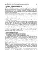
Fig. 1. The proposed industrial tracking and displacement sensors resemble the active laser
spot trackers used a) in satellite laser ranging systems and b) in laser guided missiles and
bombs.
NON-COOPERATIVE
TARGET
FOCAL
PLANE
MISFOCUSED
QUADRANT
PHOTODETECTOR
LASER SPOT
TRACKER
WARHEAD
GUIDANCE
PROPULSION
SATELLITE
CORNER CUBE
RETROREFLECTOR
ARRAY
ACTIVE LASER
ILLUMINATION
SEMI-ACTIVE LASER
ILLUMINATION
FOCAL
PLANE
a)
b)
LIGHT SPOT
LASER GUIDED MISSILE
24
has been used since the 1950s for missile homing purposes, for example (Kingsley &
Quegan 1992). Optical tracking became possible after the invention of lasers. Due to the
much shorter wavelength, optical tracking provided better precision and smaller device
size than conventional radar, and thus small-size, light-weight missile homing systems
with pinpoint accuracy became possible, for example.
The reflected beam sensors proposed in this thesis are in principle similar to the laser
spot trackers used in aerospace and military applications (Fig. 1), which use active
illumination and a misfocused QD receiver to measure the angular displacement of a
laser spot from the optical axis of the receiver. Receiver misfocusing is needed to enlarge
the tracking FOV and consequently to maintain continuous, stable tracking (Yanhai
1986, Gerson et al. 1989). In aerospace applications targets such as spacecraft, satellites
and aeroplanes are equipped with corner cube reflectors (CCRs) and the illuminating
beam overfills the target as in conventional radar trackers (Ammon & Russel 1970,
Cooke & Speck 1971, Kinnard et al. 1978, Kunkel et al. 1985, Degnan & McGarry
1997). Similar techniques have also been experimented with for geophysical
measurements (Degnan et al. 1983, Cyran 1986). In military applications the target is
typically non-cooperative, and semi-active illumination as depicted in Fig. 1b is used
(Martin Marietta Aerospace 1974, Walter 1976, Johnson RE 1979, Sparrius 1981,
Gerson et al. 1989).
1.3. Content and main contributions of the work
The laser spot trackers used in aerospace and military applications are not suitable as
such for industrial applications. Thus the main contributions of this work are related to
the modifications to be made to the operating principle and the construction of a
conventional tracking sensor in order to provide adequate performance for industrial
tracking and displacement sensing applications, which typically require an operating
range from a few metres to a few hundreds of metres together with subcentimetre or
submillimetre measurement accuracy. The content and main contributions of the work
are described below.
The operating principles, constructions and fundamental performance constraints of
the two reflected beam sensor constructions proposed in this thesis for tracking and
displacement sensing are presented in Chapter 2, and tracking sensors for the automatic
pointing of a laser beam towards a stationary or moving target, together with
rangefinding techniques for target orientation measurement, are proposed in Chapter 3.
The conventional laser spot tracker proves to be very susceptible to atmospheric
turbulence due to the receiver misfocusing used, and thus shows inadequate precision for
outdoor tracking applications requiring subcentimetre accuracy. Improved precision is
obtained by replacing the corner cube reflector with a sheet reflector.
A tracking sensor is implemented for a 3D coordinate meter in order to point its
measurement beam automatically towards a marked point on the object surface. A
practical sensor implementation based on a focused QD receiver, coaxial illumination
and a small sheet reflector provides comparable accuracy with manual aiming when the
object to be measured has diffuse reflectance properties. The practical operating
25
environment may also include specularly reflecting objects, however, in which case
sufficient tracking accuracy may not be achieved, due to strong background reflections.
The polarisation filtering proposed for reducing this error has proved to be effective and
technically feasible.
The last part of Chapter 3 deals with a rangefinding method proposed for object
distance and orientation measurement. Small fibre-coupled transmitters are attached to
the target object and their distance from a tracking receiver is measured using a pulsed
TOF rangefinder. The distance results are then used to determine the orientation of the
object with respect to the optical axis of the receiver. The functionality of the method is
demonstrated by implementing a pointing device for robot teaching purposes.
The properties and performance of two reflected beam sensor constructions designed
for displacement sensing applications are described in Chapter 4. The first of these
utilises a focused QD receiver and a square-shaped sheet reflector to measure small
displacements accurately from a distance of a few metres. Unlike the conventional
tracking sensor, the proposed construction provides position information which is
proportional to linear rather than angular displacement, and scaling which is range-
invariant and solely determined by the size of the reflector. Experimental results suggest
that the proposed sensing principle is feasible in practice.
The second sensor system, based on a focused LEP receiver and a CCR, is proposed
for long-range outdoor measurements such as the aim point trajectory measurement
needed in optical shooting practice. Ways of minimising receiver sensitivity to
atmospheric turbulence, which determines the measurement precision out of doors, are
studied. The turbulence sensitivities of the misfocused QD receiver and the LEP receiver
are compared, and it is found that the LEP receiver is less sensitive to atmospheric
fluctuations, since it can be focused, and that regardless of its higher noise it provides
better precision. Further precision improvement by adjusting the parameters of the
receiver optics or by averaging successive measurement results is found to be inefficient
in a turbulence-limited case. A method for improving turbulence-limited precision based
on multiple laterally separated reflectors is proposed and its functionality demonstrated.
Chapter 5 describes several types of PSD designed particularly for the reflected
beam sensor used in long-range displacement sensing applications. The prototypes show
that PSDs based on a dense photodetector array allow equally low sensitivity to
atmospheric turbulence to be achieved as with the LEP but with much better linearity
and incremental sensitivity.
The main results of the work are discussed in Chapter 6, and a summary is given in
Chapter 7.
2. Reflected beam sensor
2.1. Operating principle and outline of construction
A reflected beam sensor, as depicted in Fig. 2, is composed of an optical transceiver and
a reflector. The transmitter illuminates the measurement field with a uniform beam, the
divergence θ of which equals the angular field-of-view (FOV) of the receiver, and the
light reflected from the target is focused on the PSD located at the focal plane of the
receiver optics. The angular displacement of the reflector with respect to the optical axis
of the receiver is
f
x
≈
α
, (1)
where x is the displacement of the reflector image from the centre of the PSD and f the
focal length of the receiver optics.
A block diagram of a typical signal processing circuitry is depicted in Fig. 3. The
illuminator (LED, laser diode etc.) is on/off-modulated in order to distinguish the signal
from background illumination. The PSD provides four current signals the relative
amplitudes of which are proportional to the light spot position on its surface. These
current signals are amplified and their amplitudes detected using four identical signal
conditioning channels, each of which consists of a transimpedance preamplifier,
postamplifier, synchronous demodulator and A/D converter. To cope with signal level
variations, the postamplifier may include variable gain, or the transmitter power may be
variable. Position calculation is performed numerically.
27
Fig. 2. Operating principle of a reflected beam sensor.
Fig. 3. Block diagram of the signal processing circuitry of a reflected beam sensor.
2.2. Position-sensitive detectors (PSDs)
2.2.1. Operating principles
The two PSDs considered in this study are the lateral effect photodiode (LEP) and the
quadrant detector (QD), both of which are capable of measuring lateral displacement in
two dimensions. The QD (Fig. 4a) consists of four photodiodes (quadrants) positioned
symmetrically around the centre of the detector and separated by a narrow gap. The
position information is derived from the optical signal powers received by the quadrants
the electrical contribution of which then serves to define the relative position of the light
spot with respect to the centre of the device.
The LEP (Fig. 4b) consists of a single large-area photodiode, which has a uniform
resistive sheet on its cathode and similarly on its anode, and two extended ohmic
contacts on each of the two sheets. The contacts are positioned at the opposite edges of
the sheets, and the contact pairs of the sheets are oriented perpendicularly to each other.
The photon-generated current carriers divide between the contacts in proportion to the
x
α
αα
α
PSD
RECEIVER LENS
REFLECTOR
I
L
L
U
M
I
N
A
T
E
D
F
O
V
f
θ
θθ
θ
PREAMP
SYNCHRONOUS
DEMODULATOR
POSTAMP
-A
A/D
n
TX
28
resistance of the current paths between the illuminated region and the contacts. The
position of a light spot centroid can be deduced from the currents of the contact pairs,
since the resistances are directly proportional to the lengths of the current paths.
Calculation of the spot position is based on the same principle in both cases:
subtracting the opposite signals in the direction of the measured axis and dividing this
result by the sum of the same signals. This provides scaling which is insensitive to signal
level variations and whose minimum and maximum values are -1 and +1, respectively. If
the coordinate system is chosen, as shown in Fig. 4, the single axis displacement of the
light spot from the centre of the detector for a QD and an LEP are
dcba
dcba
QD
iiii
iiii
kx
+++
+−+
=
)()(
and
db
db
LEP
ii
ii
kx
+
−
=
, (2)
respectively, where i
a
, i
b
, i
c
and i
d
are the average currents of the contacts (quadrants) a,
b, c and d, and k
LEP
and k
QD
are scale factors which convert the relative displacement
values to absolute ones. Corresponding equations can be deduced for the perpendicular
direction.
Despite the apparent similarity, there are two important differences that affect the
properties of the PSDs, and consequently their suitability for different sensing
applications. The first is the effect of spot size and shape on the extent of the
measurement span and the behaviour of the lateral transfer characteristics within this
span, and the second is the difference in their noise levels and correspondingly in the
achievable precision.
Fig. 4. Outline of a) a QD and b) a LEP having an equal measurement span width d.
d
d
x
y
x
y
a
b
c
d
a
b
c
d
a)
b)
29
2.2.2. Lateral transfer characteristics
In the case of the QD the linear extent of the measurement span d and the scale factor
k
QD
are determined by the size of the light spot, as the QD will provide position
information only up to the point where the edge of the spot reaches the detector gap.
Misfocusing is typically used to adjust the spot size so that it corresponds to the desired
measurement span. The method employed here was to use a sheet reflector whose size
equals the desired measurement field at the target and to focus it accurately on the QD.
The lateral transfer characteristics of a QD depend on the spatial irradiance
distribution of the light spot. The transfer characteristics for a uniform circular spot are
non-linear, because spot movement is not proportional to the percentage of the area
which shifts between adjacent quadrants. Consequently, QDs are commonly used as
tracking and centring devices rather than as linear position sensors. Note, however, that
there exist several ways of linearising QD transfer characteristics (Paper VI, Kazovsky
1983, Carbonneau & Dubois 1986) and that they may therefore be used for linear
displacement measurements as well. The scale factor k
QD
for a uniform circular spot near
the centre of the measurement span is d
s
π/8, where d
s
is the diameter of the spot
(Kazovsky 1983, Yanhai 1986, Young et al. 1986).
The measurement span of the LEP is determined by the size of its active area. It
provides accurate position information independent of the size of the light spot, because
its signals are a direct measure of the position of the spot centroid from the edges of the
detector. Thus, unlike with the situation with the QD, there is no need to adjust the spot
size by misfocusing. The transfer characteristics of a LEP are linear and the scale factor
k
LEP
is d/2, where d is the width of the LEP active area.
2.3. Limits of measurement accuracy
The limits for the measurement accuracy are set by the achievable signal to noise ratio
(SNR) and the reflector background contrast, defined as the ratio of the powers of the
signals received from the reflector and the illuminated background. The former
determines the achievable precision and the latter the lower bound for systematic errors.
2.3.1. Precision of the LEP and QD receivers
The incremental sensitivity of the LEP and QD receivers depends on the lateral transfer
characteristics and signal current distribution (head-or-tail-current v. head-and-tail
current) of the PSDs, on noises originating from the PSDs, preamplifier and background,
and on the noise correlation between signal channels. The results of the analysis,
including the above factors, are presented in the following. First the relation between the
SNR and precision is determined (noise sensitivity), and then the dominating noise
sources are evaluated, and finally the precisions of the LEP and QD receivers are
compared under conditions of low and high background illumination.