ASTM D4539 10 Standard Test Method for Filterability of Diesel Fuels by LowTemperature Flow Test (LTFT)
Bạn đang xem bản rút gọn của tài liệu. Xem và tải ngay bản đầy đủ của tài liệu tại đây (142.86 KB, 6 trang )
Designation: D4539 − 10
Standard Test Method for
Filterability of Diesel Fuels by Low-Temperature Flow Test
(LTFT)
1
This standard is issued under the fixed designation D4539; the number immediately following the designation indicates the year of
original adoption or, in the case of revision, the year of last revision. A number in parentheses indicates the year of last reapproval. A
superscript epsilon (´) indicates an editorial change since the last revision or reapproval.
1. Scope*
1.1 This test method covers estimating the filterability of
diesel fuels in some automotive equipment at low tempera-
tures.
1.2 The values stated in SI units are to be regarded as
standard. No other units of measurement are included in this
standard.
1.3 Warning—Mercury has been designated by EPA and
many state agencies as a hazardous material that can cause
central nervous system, kidney, and liver damage. Mercury, or
its vapor, may be hazardous to health and corrosive to
materials. Caution should be taken when handling mercury and
mercury-containing products. See the applicable product Ma-
terial Safety Data Sheet (MSDS) for details and EPA’s website
( for additional informa-
tion. Users should be aware that selling mercury or mercury-
containing products, or both, in your state may be prohibited by
state law.
1.4 This standard does not purport to address all of the
safety concerns, if any, associated with its use. It is the
responsibility of the user of this standard to establish appro-
priate safety and health practices and determine the applica-
bility of regulatory limitations prior to use. For specific
warning statements, see
1.3, 8.1, 8.2.1, 8.3, 8.5, and Annex A1.
2. Referenced Documents
2.1 ASTM Standards:
2
D97 Test Method for Pour Point of Petroleum Products
D975 Specification for Diesel Fuel Oils
D1655 Specification for Aviation Turbine Fuels
D2500 Test Method for Cloud Point of Petroleum Products
D3117 Test Method for Wax Appearance Point of Distillate
Fuels
(Withdrawn 2010)
3
D3699 Specification for Kerosine
D4057 Practice for Manual Sampling of Petroleum and
Petroleum Products
D4177 Practice for Automatic Sampling of Petroleum and
Petroleum Products
E1 Specification for ASTM Liquid-in-Glass Thermometers
2.2 Coordinating Research Council, Inc.
CRC Report No. 528 Diesel Fuel Low-Temperature Oper-
ability Field Test
4
2.3 Canadian General Standards Board:
CAN/CGSB-3.0, No. 14.01-M86, Low Temperature Flow
Test (LTFT) for Diesel Fuels
5
NOTE 1—CAN/CGSB-3.0, No. 140.1-M86 is essentially equivalent to
Test Method D4539, but the differences in apparatus and procedures may
or may not yield different results.
3. Summary of Test Method
3.1 The temperature of a series of test specimens of fuel is
lowered at a prescribed cooling rate. Commencing at a desired
test temperature and at each 1°C interval thereafter, a separate
specimen from the series is filtered through a 17-µm screen
until a minimum LTFT pass temperature is obtained. The
minimum LTFT pass temperature is the lowest temperature,
expressed as a multiple of 1°C, at which a test specimen can be
filtered in 60 s or less.
3.2 Alternatively, a single specimen may be cooled as
described under
3.1 and tested at a specified temperature to
determine whether it passes or fails at that temperature.
4. Significance and Use
4.1 The Low Temperature Flow Test results are indicative of
the low temperature flow performance of the test fuel in some
diesel vehicles (according to CRC Report No. 528). The test
method is especially useful for the evaluation of fuels contain-
ing flow improver additives.
1
This test method is under the jurisdiction of Committee D02 on Petroleum
Products and Lubricants and is the direct responsibility of Subcommittee D02.07 on
Flow Properties.
Current edition approved Oct. 1, 2010. Published November 2010. Originally
approved in 1985. Last previous edition approved in 2009 as D4539–09. DOI:
10.1520/D4539-10.
2
For referenced ASTM standards, visit the ASTM website, www.astm.org, or
contact ASTM Customer Service at For Annual Book of ASTM
Standards volume information, refer to the standard’s Document Summary page on
the ASTM website.
3
The last approved version of this historical standard is referenced on
www.astm.org.
4
Available from Coordinating Research Council, Inc., 219 Perimeter Center
Parkway, Atlanta, GA 30346.
5
Available from CGSB Sales Centre, Ottawa, Canada K1A 1G6.
*A Summary of Changes section appears at the end of this standard
Copyright © ASTM International, 100 Barr Harbor Drive, PO Box C700, West Conshohocken, PA 19428-2959. United States
1
Copyright by ASTM Int'l (all rights reserved); Sat Oct 19 11:51:23 EDT 2013
Downloaded/printed by
Pontifcia Universidade Catlica do Rio Grande do Sul pursuant to License Agreement. No further reproductions authorized.
4.2 The test method can be used to supplement other
measurements of diesel fuel low temperature behavior (in
accordance with Test Methods
D97, D2500, and D3117).
5. Apparatus
5.1 Glass Specimen Vessels, (Borosilicate heat-resistant
glass or equivalent) several 300-mL, clear, heat resistant,
wide-mouthed glass bottles having markings indicating 200 6
10 mL and 50–60 mm ID or clear, heat resistant, tall form
beakers with no pour spouts and equivalent dimensions.
5.2 Glass Receiver Vessels, clear, heat resistant, glass con-
tainers graduated through 180 mL in 10 6 2 mL increments.
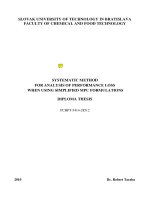
5.3 Filtering Assembly (see
Fig. 1), including a storage lid
or some other form of cover, glass tubing, flexible fuel resistant
tubing, pinch clamp or valve, and rubber stopper, or other
means to provide a vacuum seal.
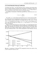
5.4 Filter Assembly
6
, as shown in detail in Fig. 2, for each
sample container (300-mL beaker). 304SS sintered screen
7
is a
twill Dutch weave mesh with a nominal filtration rating of 17
µm. The mesh is 65 wires/cm by 303/315 wires/cm. The wire
strands have diameters of 0.0071 cm and 0.0046 cm, respec-
tively. The nominal filtration rating indicates a 98 % removal
by mass weight of all particles equal to or greater than 17 µm.
5.5 Programmable Cooling System, capable of cooling mul-
tiple specimens to the desired temperature at a mean rate of
1.0°C per hour between +10°C and −30°C. Absolute deviation
of any single temperature point along the prescribed ramp
function must not exceed 0.5°C in any specimen. The system’s
size and shape are optional. Either liquid or air baths are
acceptable.
5.6 Stop Watch or Electric Timer, capable of measuring
tenths of a second.
5.7 Vacuum System, capable of maintaining a constant
vacuum of 20.0 6 0.2 kPa below atmospheric pressure at the
receiver for the duration of each determination.
5.8 Temperature Measuring Device (Liquid-in-glass
thermometer)—Conforming to specifications for ASTM Ther-
mometer 114C for air baths or ASTM Thermometer 5C for
liquid baths in accordance with Specification
E1, or any other
temperature measuring device with equal or better accuracy
and equal temperature response.
6. Reagents
6.1 Jet A Aviation Turbine Fuel—As specified in Specifica-
tion
D1655, kerosine, as specified in Specification D3699,
Grade No. 1 (or Grade Low Sulfur No. 1), as specified in
Specification
D975, or equivalent liquid that will not separate
at temperatures down to –30°C.
6.2 Heptane—Reagent grade. (Warning—Flammable. See
A1.2.)
6.3 Acetone—Reagent grade. (Warning—Flammable. See
A1.1.)
7. Sampling
7.1 Obtain a sample in accordance with Practice
D4057,or
by Practice D4177.
7.2 Each specimen test requires a minimum of 200 mL.
Ensure that sufficient sample is obtained to perform the
subsequent series of test specimens according to the procedure
followed (see Section
3).
6
The sole source of supply of the filter assembly known to the committee at this
time is Lawler Manufacturing Corp., Kilmer Ct., Edison, NJ and Alberta Research
Council, Fuels and Lubricants Group, 250 Karl Clark Rd., Edmonton, Alberta,
Canada. If you are aware of alternative suppliers, please provide this information to
ASTM International Headquarters. Your comments will receive careful consider-
ation at a meeting of the responsible technical committee
1
, which you may attend.
7
The sole source of supply of suitable filter cloth known to the committee at this
time is Pall Aerospace Co., Pall Aeropower Corp., 6301 49
th
St. N, Pinellas Park, FL
33781. If you are aware of alternative suppliers, please provide this information to
ASTM International Headquarters. Your comments will receive careful consider-
ation at a meeting of the responsible technical committee
1
, which you may attend.
FIG. 1 LTFT Sample Filtration Assembly
D4539 − 10
2
Copyright by ASTM Int'l (all rights reserved); Sat Oct 19 11:51:23 EDT 2013
Downloaded/printed by
Pontifcia Universidade Catlica do Rio Grande do Sul pursuant to License Agreement. No further reproductions authorized.
8. Procedure
8.1 Filter a fresh specimen of test fuel at 15°C or higher,
through dry, lintless filter paper, having a nominal filtration
rating of less than 17 µm. (Warning—Combustible liquid. See
A1.3.)
NOTE 2—The purpose of this filtration step is to remove any contami-
nants that interfere with the effectiveness of low temperature flow
improver additives. However, this pre-filtration step may remove contami-
nants that affect the low temperature flow properties of the fuel in actual
service. Users of this test method may find it helpful to run the test with
and without the pre-filtration step to compare results and in recognition
that the precision of the test method will not apply if the pre-filtration step
is not carried out.
8.2 Clean and inspect the filter assembly before each test.
Filters obtained from the manufacturer are already standard-
ized.
Appendix X1 provides a procedure for checking the filter
performance, if desired.
8.2.1 Clean the assembled filter with two solvents using a
vacuum to draw the solvents through the screen. Begin with
three successive washes of at least 50 mL of heptane
(Warning—Flammable. See
A1.2). Follow with three succes-
sive washes of at least 50 mL of acetone (Warning—
Extremely flammable. See
A1.1). Air dry the filters after
washing.
8.2.2 Visually inspect each filter assembly for screen dam-
age or the presence of particulates. Discard any damaged filter
screens. Reclean any filter screens containing particulates. If
the standardization of the filter is suspect, obtain a new filter.
Alternately, return the filter to the manufacturer for verifica-
tion;
Appendix X1 provides a procedure for checking the filter
performance.
8.3 Pour 200 mL of clean, dry fuel into each of the several
300-mL beakers. (Warning—Combustible liquid. See
A1.3.)
8.4 Insert the clean filter assembly into each specimen
container and tightly cover the joint (Point A in
Fig. 1) and lid
with aluminum foil to exclude condensation.
8.5 Insert a temperature measuring device into one or more
separate, identical glass specimen bottles or beaker(s) contain-
ing 200 mL of Jet A aviation turbine fuel kerosine, or Grade
No. 1 (or Grade Low Sulfur No. 1) or equivalent liquid that
will not phase separate at temperatures down to −30°C.
FIG. 2 LTFT Filter Assembly
D4539 − 10
3
Copyright by ASTM Int'l (all rights reserved); Sat Oct 19 11:51:23 EDT 2013
Downloaded/printed by
Pontifcia Universidade Catlica do Rio Grande do Sul pursuant to License Agreement. No further reproductions authorized.
(Warning—Combustible liquid. See A1.3.) Place the tempera-
ture measuring portion of the device at or near the center of the
bottle or beaker approximately half way between the top and
the bottom of the liquid.
8.6 Place the specimen bottles or beaker (from
8.3 through
8.5) into the cooling bath at a temperature that is at least 5°C
above the wax appearance point (Test Method D3117) or cloud
point (Test Method
D2500) of the fuel under test. During
multiple specimen testing, a sufficient number of temperature
monitoring vessels (from
8.5) must be distributed throughout
the cooling bath to insure all test specimen temperatures
conform with precision requirements. The positioning of all
bottles or beakers shall permit unimpeded circulation of the
cooling medium across their bottoms and sides.
8.7 Close the cooling bath’s door, if it has one.
8.8 Start the temperature programmer at a rate of −1.0°C/h.
8.9 Before the sample reaches the desired test temperature,
check the following:
8.9.1 Apply the pinch clamp or close the valve at Point B in
Fig. 1.
8.9.2 Place an empty receiver vessel in position.
8.9.3 Adjust the vacuum to 20.0 6 0.2 kPa below atmo-
spheric pressure.
8.9.4 Reset the timer.
8.10 When the specimen has cooled to the desired testing
temperature, use the filter assembly stem to gently stir (15
revolutions at approximately 1 turn/s) the specimen to disperse
any settled wax crystals. Remove the aluminum foil and
connect the filtration apparatus joint at Point A in
Fig. 1.Ifthe
specimen has to be removed from the cooling bath for
filtration, these steps shall be completed within 1 min.
8.11 Filter the specimen by removing the pinch clamp or
open the valve at Point B in
Fig. 1 while simultaneously
starting the timer. If necessary, adjust the vacuum system to
maintain a vacuum of 20.0 + 0.2 kPa below atmospheric
pressure.
8.12 Reapply the pinch clamp or close the valve at Point B
in
Fig. 1 at precisely 60 s or when suction is lost, whichever
occurs first. Record the volume of specimen filtered in millili-
tres and the testing temperature in degrees Celsius.
8.13 Pass—Fail Criteria:
8.13.1 Passing Result—The result is considered a pass if
most of the specimen has been siphoned into the receiver
vessel within 60 s, and suction is lost due to the low level of
specimen remaining in the specimen vessel.
NOTE 3—Typically, a volume of approximately 180 mL will be
collected in the receiver vessel in a passing result, but this volume may
vary due to differences in specimen vessel dimensions and the
temperature/volume characteristics of the fuel.
8.13.2 Failing Result—The result is considered a fail if
suction is not lost within 60 s.
8.14 To determine the minimum LTFT pass temperature,
repeat
8.9 through 8.12 on subsequent test specimens that have
been cooled 1°C lower than the previous test temperature, until
at least one passing result and one failing result are obtained
(see
8.13.1 and 8.13.2).
8.15 Alternatively, cool a single specimen to a desired
temperature and determine whether a passing (
8.13.1)ora
failing (8.13.2) result is obtained.
9. Report
9.1 Report the temperature of the last passing result re-
corded in
8.14 as:
Minimum LTFT Pass Temperature =_______°C.
9.2 Alternatively, report the result recorded in Step
8.15 as:
Pass or Fail at ________°C.
10. Precision and Bias
10.1 Precision—The precision data were obtained in a
cooperative program in which fuels were investigated over the
temperature range from −10 to −25°C. The precision of this
test method as determined by the statistical examination of
interlaboratory test results is as follows:
10.1.1 Repeatability—The difference between successive
results obtained by the same operator with the same apparatus
under constant operating conditions on identical test material
would, in the long run, in the normal and correct operation of
the test method exceed the following value only in one case in
twenty.
Repeatability 5 27C (1)
10.1.2 Reproducibility—The difference between two single
and independent results obtained by different operators work-
ing in different laboratories on identical test material would, in
the long run, in the normal and correct operation of the test
method, exceed the following value only in one case in twenty.
Reproducibility 5 47C (2)
10.2 Bias—There being no criteria for measuring bias in
these test product combinations, no statement of bias can be
made.
11. Keywords
11.1 diesel fuel; filterability; flow; low temperature; LTFT
D4539 − 10
4
Copyright by ASTM Int'l (all rights reserved); Sat Oct 19 11:51:23 EDT 2013
Downloaded/printed by
Pontifcia Universidade Catlica do Rio Grande do Sul pursuant to License Agreement. No further reproductions authorized.
ANNEX
(Mandatory Information)
A1. WARNING STATEMENTS
A1.1 Acetone
A1.1.1 (Warning—Extremely flammable.)
A1.1.2 (Warning—Vapors may cause flash fire.)
A1.1.3 (Warning—Keep away from heat, sparks, and open
flame.)
A1.1.4 (Warning—Keep container closed.)
A1.1.5 (Warning—Use with adequate ventilation.)
A1.1.6 (Warning—Avoid buildup of vapors, and eliminate
all sources of ignition, especially non-explosion proof electri-
cal apparatus and heaters.)
A1.1.7 (Warning—Avoid prolonged breathing of vapor or
spray mist.)
A1.1.8 (Warning—Avoid contact with eyes or skin.)
A1.2 n-Heptane
A1.2.1 (Warning—Flammable. Harmful if inhaled.)
A1.2.2 (Warning—Keep away from heat, sparks, and open
flame.)
A1.2.3 (Warning—Keep container closed.)
A1.2.4 (Warning—Use with adequate ventilation.)
A1.2.5 (Warning—Avoid prolonged breathing of vapor or
spray mist.)
A1.2.6 (Warning—Avoid prolonged or repeated skin con-
tact.)
A1.3 Combustible Liquid
A1.3.1 (Warning—Combustible. Vapor harmful.)
A1.3.2 (Warning—Keep away from heat, sparks, and open
flame.)
A1.3.3 (Warning—Keep container closed.)
A1.3.4 (Warning—Use with adequate ventilation.)
A1.3.5 (Warning—Avoid prolonged breathing of vapor or
spray mist.)
A1.3.6 (Warning—Avoid prolonged or repeated skin con-
tact.)
A1.4 Mercury
A1.4.1 (Warning—Poison. May be harmful or fatal if
inhaled or swallowed.)
A1.4.2 (Warning—Vapor harmful, emits toxic fumes when
heated.)
A1.4.3 (Warning—Vapor pressure at normal room tem-
perature exceeds threshold limit value for occupational expo-
sure.)
A1.4.4 (Warning—Do not breathe vapor.)
A1.4.5 (Warning—Keep container closed.)
A1.4.6 (Warning—Use with adequate ventilation.)
A1.4.7 (Warning—Do not take internally.)
A1.4.8 (Warning—Cover exposed surfaces with water, if
possible, to minimize evaporation.)
A1.4.9 (Warning—Do not heat.)
A1.4.10 (Warning—Keep recovered mercury in tightly
sealed container prior to sale or purification. Do not throw in
sink or in rubbish.)
APPENDIX
(Nonmandatory Information)
X1. LTFT WIRE FILTER SCREEN STANDARDIZATION PROCEDURE
X1.1 Procedure
X1.1.1 Dismantle and inspect the wire filter screen assem-
bly. Discard any damaged screens.
X1.1.2 Reassemble and wash the filter assembly as speci-
fied in
8.2.
X1.1.3 Filter the Vistone
8
A-30 reference oil through dry,
lintless filter paper, having a normal filtration rating of less than
17 µm at room temperature.
X1.1.4 Pour 150 mL of clean, dry Vistone A-30 into a
300-mL heat resistant tall-form beaker (Borosilicate heat-
resistant glass or equivalent) with no pour spout.
X1.1.5 Insert the filter assembly into the sample.
X1.1.6 Insert a thermometer into the beaker and wait until
the temperature reading stabilizes.
X1.1.7 Filter the Vistone A-30 by applying a vacuum of
20.0 6 0.2 kPa below atmospheric pressure while simultane-
ously starting the stopwatch.
X1.1.8 Stop the timer at the instant the filter assembly loses
suction on the oil and begins drawing in air.
8
Vistone is a registered trademark of Infineum International Limited.
D4539 − 10
5
Copyright by ASTM Int'l (all rights reserved); Sat Oct 19 11:51:23 EDT 2013
Downloaded/printed by
Pontifcia Universidade Catlica do Rio Grande do Sul pursuant to License Agreement. No further reproductions authorized.
X1.1.9 Record the filtration time in seconds and the filtra-
tion temperature to the nearest 0.5°C.
X1.1.10 Calculate the temperature correction factor corre-
sponding to the filtration temperature using the following
equations. The viscosity of the Vistone A-30 reference oil will
be provided by the vendor.
loglog
~
v
t
10.7
!
5 A 2 BlogT (X1.1)
C
t
5 v
20
/v
t
(X1.2)
where:
v
t
= viscosity of reference fluid at specified temperature,
mm
2
v
20
= viscosity of reference fluid at 20°C, mm
2
,
A, B = constants to be solved,
C
t
= temperature correction factor at specified tempera-
ture,
T = temperature in Kelvin at which v
t
is determined,
T = 273.1 + °C.
Example: Determine temperature correction factor at 10°C.
If the viscosities for Vistone A-30 are:
27.04 mm
2
/s (cSt) at 40°C
5.38 mm
2
/s (cSt) at 100°C
X1.1.11 Enter the viscosity and corresponding temperature
data in (
Eq X1.1):
loglog
~
v
t
10.7
!
5 A 2 BlogT (X1.3)
loglog
~
27.0410.7
!
5 A 2 Blog
~
273.1140
!
(X1.4)
loglog
~
5.3810.7
!
5 A 2 Blog
~
273.11100
!
(X1.5)
X1.1.12 Solve for A and B:
A 5 8.8500, B 5 3.4823 (X1.6)
X1.1.13 Determine the viscosity of Vistone A-30 at 20°C
and 10°C using (Eq X1.1)
loglog
~
v
20
10.7
!
5 8.8500 2 3.4823log
~
273.1120
!
(X1.7)
v
20
5 64.75 (X1.8)
loglog
~
v
10
10.7
!
5 8.8500 2 3.4823log
~
273.1110
!
(X1.9)
v
10
5 111.33 (X1.10)
X1.1.14 Calculate the temperature correction factor at 10°C
using (
Eq X1.2)
C
t
5 v
20
/v
t
(X1.11)
C
10
5 64.75/111.33 5 0.582 (X1.12)
X1.1.15 Multiply the actual filtration time in seconds by the
correction factor to obtain the corrected filtration time. (Ex-
ample: for an actual filtration time of 79 s at 10°C, the
corrected filtration time would be 79 × 0.582 = 46 s (
X1.1.11),
and the screen would be reported as acceptable.)
X1.2 Report
X1.2.1 If the corrected filtration time falls between 45 and
53 s, inclusive, the screen is reported as acceptable for use in
the LTFT. If the corrected filtration time falls outside this
range, the screen is unacceptable and should be discarded.
SUMMARY OF CHANGES
Committee D02.07 has identified the location of selected changes to this standard since the last issue
(D4539–09) that may impact the use of this standard. (Approved Oct. 1, 2010.)
(1) Added
Note 2.
Committee D02.07 has identified the location of selected changes to this standard since the last issue
(D4539-03
´1
) that may impact the use of this standard. (Approved April 15, 2009.)
(1) Added mercury caveat in
1.3.
ASTM International takes no position respecting the validity of any patent rights asserted in connection with any item mentioned
in this standard. Users of this standard are expressly advised that determination of the validity of any such patent rights, and the risk
of infringement of such rights, are entirely their own responsibility.
This standard is subject to revision at any time by the responsible technical committee and must be reviewed every five years and
if not revised, either reapproved or withdrawn. Your comments are invited either for revision of this standard or for additional standards
and should be addressed to ASTM International Headquarters. Your comments will receive careful consideration at a meeting of the
responsible technical committee, which you may attend. If you feel that your comments have not received a fair hearing you should
make your views known to the ASTM Committee on Standards, at the address shown below.
This standard is copyrighted by ASTM International, 100 Barr Harbor Drive, PO Box C700, West Conshohocken, PA 19428-2959,
United States. Individual reprints (single or multiple copies) of this standard may be obtained by contacting ASTM at the above
address or at 610-832-9585 (phone), 610-832-9555 (fax), or (e-mail); or through the ASTM website
(www.astm.org). Permission rights to photocopy the standard may also be secured from the ASTM website (www.astm.org/
COPYRIGHT/).
D4539 − 10
6
Copyright by ASTM Int'l (all rights reserved); Sat Oct 19 11:51:23 EDT 2013
Downloaded/printed by
Pontifcia Universidade Catlica do Rio Grande do Sul pursuant to License Agreement. No further reproductions authorized.