ASTM D6079 11 Standard Test Method for Evaluating Lubricity of Diesel Fuels by the HighFrequency Reciprocating Rig (HFRR)
Bạn đang xem bản rút gọn của tài liệu. Xem và tải ngay bản đầy đủ của tài liệu tại đây (499.38 KB, 8 trang )
Designation: D6079 − 11
Standard Test Method for
Evaluating Lubricity of Diesel Fuels by the High-Frequency
Reciprocating Rig (HFRR)
1
This standard is issued under the fixed designation D6079; the number immediately following the designation indicates the year of
original adoption or, in the case of revision, the year of last revision. A number in parentheses indicates the year of last reapproval. A
superscript epsilon (´) indicates an editorial change since the last revision or reapproval.
1. Scope*
1.1 This test method covers the evaluation of the lubricity of
diesel fuels using a high-frequency reciprocating rig (HFRR).
1.2 This test method is applicable to middle distillate fuels,
such as Grades No. 1-D S15, S500, and S5000, and Grades No.
2-D S15, S500, and S5000 diesel fuels, in accordance with
Specification
D975; and other similar petroleum-based fuels
which can be used in diesel engines. This test method is
applicable to biodiesel blends. B5 was included in the round
robin program that determined the precision statement.
NOTE 1—It is not known that this test method will predict the
performance of all additive/fuel combinations. Additional work is under-
way to establish this correlation and future revisions of this test method
may be necessary once this work is complete.
1.3 The values stated in SI units are to be regarded as
standard. No other units of measurement are included in this
standard.
1.4 This standard does not purport to address all of the
safety concerns, if any, associated with its use. It is the
responsibility of the user of this standard to establish appro-
priate safety and health practices and determine the applicable
regulatory limitations prior to use. Specific warning statements
are given in Section
7.
2. Referenced Documents
2.1 ASTM Standards:
2
D975 Specification for Diesel Fuel Oils
D4057 Practice for Manual Sampling of Petroleum and
Petroleum Products
D4177 Practice for Automatic Sampling of Petroleum and
Petroleum Products
D4306 Practice for Aviation Fuel Sample Containers for
Tests Affected by Trace Contamination
D6078 Test Method for Evaluating Lubricity of Diesel Fuels
by the Scuffing Load Ball-on-Cylinder Lubricity Evalua-
tor (SLBOCLE)
E18 Test Methods for Rockwell Hardness of Metallic Ma-
terials
E92 Test Method for Vickers Hardness of Metallic Materials
(Withdrawn 2010)
3
2.2 SAE Standard:
4
SAE-AMS 6440 Steel, Bars, Forgings, and Tubing, 1.45 Cr
(0.93-1.05C) (SAE 52100), for Bearing Applications
2.3 ISO Standard:
5
ISO 3290 Roller Bearings, Balls – Dimensions and toler-
ances
3. Terminology
3.1 Definitions:
3.1.1 boundary lubrication, n—a condition in which the
friction and wear between two surfaces in relative motion are
determined by the properties of the surfaces and the properties
of the contacting fluid, other than bulk viscosity.
3.1.1.1 Discussion—Metal to metal contact occurs and the
chemistry of the system is involved. Physically adsorbed or
chemically reacted soft films (usually very thin) support
contact loads. As a result, some wear is inevitable.
3.1.2 lubricity, n—a qualitative term describing the ability
of a fluid to affect friction between, and wear to, surfaces in
relative motion under load.
3.1.2.1 Discussion—In this test method, the lubricity of a
fluid is evaluated by the wear scar, in microns, produced on an
oscillating ball from contact with a stationary disk immersed in
the fluid operating under defined and controlled conditions.
3.2 Abbreviations:
1
This test method is under the jurisdiction of ASTM Committee D02 on
Petroleum Products, Liquid Fuels, and Lubricants and is the direct responsibility of
Subcommittee D02.E0 on Burner, Diesel, Non-Aviation Gas Turbine, and Marine
Fuels.
Current edition approved March 1, 2011. Published April 2011. Originally
approved in 1999. Last previous edition approved in 2004 as D6079–04
ε1
. DOI:
10.1520/D6079-11.
This test method was developed by ISO/TC22/SC7/WG6 and is a part of ISO
12156.
2
For referenced ASTM standards, visit the ASTM website, www.astm.org, or
contact ASTM Customer Service at For Annual Book of ASTM
Standards volume information, refer to the standard’s Document Summary page on
the ASTM website.
3
The last approved version of this historical standard is referenced on
www.astm.org.
4
Available from SAE International (SAE), 400 Commonwealth Dr., Warrendale,
PA 15096-0001, .
5
Available from American National Standards Institute (ANSI), 25 W. 43rd St.,
4th Floor, New York, NY 10036, .
*A Summary of Changes section appears at the end of this standard
Copyright © ASTM International, 100 Barr Harbor Drive, PO Box C700, West Conshohocken, PA 19428-2959. United States
1
Copyright by ASTM Int'l (all rights reserved); Sat Oct 19 11:54:30 EDT 2013
Downloaded/printed by
Pontifcia Universidade Catlica do Rio Grande do Sul pursuant to License Agreement. No further reproductions authorized.
3.2.1 HFRR—high frequency reciprocating rig
3.2.2 WSD—wear scar diameter
4. Summary of Test Method
4.1 A 2-mL test specimen of fuel is placed in the test
reservoir of an HFRR.
4.2 A vibrator arm holding a nonrotating steel ball and
loaded with a 200-g mass is lowered until it contacts a test disk
completely submerged in the fuel. When the fuel temperature
has stabilized, the ball is caused to rub against the disk with a
1-mm stroke at a frequency of 50 Hz for 75 min.
4.3 The test fuel temperature is maintained at 60°C and the
ambient relative humidity is maintained between 30 % and
85 %.
4.4 At the conclusion of the test, the upper specimen holder
is removed from the vibrator arm and cleaned. The image of
the wear scar is captured using the microscope digital camera,
and the dimensions of the major and minor axes of the wear
scar are measured and recorded.
5. Significance and Use
5.1 Diesel fuel injection equipment has some reliance on
lubricating properties of the diesel fuel. Shortened life of
engine components, such as diesel fuel injection pumps and
injectors, has sometimes been ascribed to lack of lubricity in a
diesel fuel.
5.2 The trend of HFRR test results to diesel injection system
pump component distress due to wear has been demonstrated
in pump rig tests for some fuel/hardware combinations where
boundary lubrication is believed to be a factor in the operation
of the component.
6
5.3 The wear scar generated in the HFRR test is sensitive to
contamination of the fluids and test materials, the temperature
of the test fuel, and the ambient relative humidity. Lubricity
evaluations are also sensitive to trace contaminants acquired
during test fuel sampling and storage.
5.4 The HFRR and Scuffing Load Ball on Cylinder Lubric-
ity Evaluator (SLBOCLE, Test Method
D6078) are two meth-
ods for evaluating diesel fuel lubricity. No absolute correlation
has been developed between the two test methods.
5.5 The HFRR may be used to evaluate the relative effec-
tiveness of diesel fuels for preventing wear under the pre-
scribed test conditions. Correlation of HFRR test results with
field performance of diesel fuel injection systems has not yet
been determined.
5.6 This test method is designed to evaluate boundary
lubrication properties. While viscosity effects on lubricity in
this test method are not totally eliminated, they are minimized.
6. Apparatus
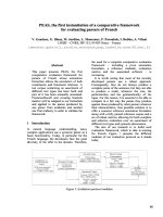
6.1 High-Frequency Reciprocating Rig (HFRR),
7,8
(see Fig.
1
) capable of rubbing a steel ball loaded with a 200-g mass
against a stationary steel disk completely submerged in a test
fuel. The apparatus uses a 1-mm stroke length at a frequency of
50 Hz for 75 min. Complete operating conditions are listed in
Table 1.
6.2 Test Reservoir, capable of holding a test disk in a rigid
manner beneath the test fuel. The temperature of this reservoir,
and consequently the test fuel contained in it, is maintained by
means of a closely attached electrically controlled heater pad.
6.3 Control Unit
7,8
for controlling stroke length, frequency,
test reservoir temperature, friction force, electrical contact
potential, and test duration, with an electronic data acquisition
and control system.
6.4 Microscope, with Digital Camera
7,8
capable of 100×
magnification, installed and calibrated according to manufac-
turer instructions, capable of capturing a crisp image of the
wear scar. Camera system resolution should be a minimum of
2048 × 1536 pixels. The measurement system should allow
horizontal and vertical measurement devices or cursors to be
positioned at the wear scar boundaries with an accuracy of 1
micron.
6.5 Cleaning Bath, ultrasonic seamless stainless steel tank
with adequate capacity and a cleaning power of 40 W or
greater.
6.6 Desiccator, capable of storing test disks, balls, and
hardware.
7. Reagents and Materials
7.1 Acetone, reagent grade (Warning—Extremely flam-
mable. Vapors may cause flash fire).
7.2 Compressed Air, containing less than 0.1 ppmv hydro-
carbons and 50 ppmv water. (Warning—Compressed gas
6
Nikanjam, M., Crosby, T., Henderson, P., Gray, C., Meyer, K, and Davenport,
N., “ISO Diesel Fuel Lubricity Round Robin Program,” SAE, Paper No. 952372,
SAE Fuels and Lubricants Meeting, Oct. 16-19, 1995, Toronto, Canada.
7
The sole source of supply of the apparatus known to the committee at this time
is PCS Instruments, 78 Stanley Gardens, London W3 7SZ, England.
8
If you are aware of alternative suppliers, please provide this information to
ASTM International Headquarters. Your comments will receive careful consider-
ation at a meeting of the responsible technical committee,
1
which you may attend.
FIG. 1 Schematic Diagram of HFRR (not including instrumenta-
tion)
D6079 − 11
2
Copyright by ASTM Int'l (all rights reserved); Sat Oct 19 11:54:30 EDT 2013
Downloaded/printed by
Pontifcia Universidade Catlica do Rio Grande do Sul pursuant to License Agreement. No further reproductions authorized.
under high pressure. Use with extreme caution in the presence
of combustible material.)
7.3 Gloves, appropriate for the reagents used.
7.4 Reference Fluids:
7.4.1 Fluid A
9
—High lubricity reference (Warning—
Flammable). Store in clean, borosilicate glass with an alumi-
num foil-lined insert cap or a fully epoxy-lined metal container.
Store in dark area.
7.4.2 Fluid B
9
—Low lubricity reference (Warning—
Flammable. Vapor harmful). Store in clean, borosilicate glass
with an aluminum foil-lined insert cap or a fully epoxy-lined
metal container. Store in a dark area.
7.5 Heptane, reagent grade (Warning—Extremely flam-
mable. Vapors may cause flash fire.)
7.6 Isooctane, reagent grade (Warning—Extremely flam-
mable. Vapors may cause flash fire.)
7.7 2–propanol, reagent grade (Warning—Extremely flam-
mable. Vapors may cause flash fire.)
7.8 Test Ball,
7,8
(Grade 28 per ISO 3290) of SAE-AMS 6440
steel, with a diameter of 6.00 mm, having a Rockwell hardness
“C” scale (HRC) number of 58 - 66, in accordance with Test
Methods
E18.
7.9 Test Disk,
7,8
—10 mm disk of SAE-AMS 6440 steel
machined from annealed rod, having a Vickers hardness “HV
30,” in accordance with Specification
E92, a scale number of
190-210, turned, lapped, and polished to a surface finish of less
than 0.02 µm R
a
.
7.10 Wiper, wiping tissue, light-duty, lint-free, hydrocarbon-
free, disposable.
8. Sampling and Sample Containers
8.1 Unless otherwise specified, samples shall be taken by
the procedure described in Practice
D4057 or Practice D4177.
8.2 Because of the sensitivity of lubricity measurements to
trace materials, sample containers shall be only fully epoxy-
lined metal, amber borosilicate glass, or polytetrafluorethylene
(PTFE), cleaned and rinsed thoroughly at least three times with
the product to be sampled before use, as specified under
Containers for Lubricity Testing in Practice
D4306.
8.3 New sample containers are preferred, but if not
available, the Containers for Lubricity Testing section of
Practice
D4306 gives guidance on suitable cleaning procedures
for each type of container.
9. Preparation of Apparatus
9.1 Test Disks, (as received):
9.1.1 Place disks in a clean beaker. Transfer a sufficient
volume of heptane or 50/50 isooctane/2-propanol into the
beaker to completely cover the test disks.
9.1.2 Place beaker in ultrasonic cleaner and turn on for 7
min.
9.1.3 Handle all clean test pieces with clean forceps. Re-
move the test discs and repeat the above cleaning procedure
from
9.1.1 with acetone for 2 min.
9.1.4 Dry and store in desiccator.
NOTE 2—Drying operations can be accomplished using compressed air
jet at 140 to 210 kPa-pressure.
9.2 Test Balls, (as received)—The test balls are to be cleaned
following the same procedure, 9.1.1 to 9.1.4, as for the test
disks.
9.3 Hardware—All hardware and utensils that come into
contact with the test disks, test balls, or test fuel, shall be
cleaned by washing thoroughly with heptane or 50/50
isooctane/2-propanol, rinsed with acetone, and dried.
10. Test Apparatus Inspection and Verification
10.1 Recommended Calibration Intervals:
10.1.1 Stroke length—every three months.
10.1.2 Temperature probes—every twelve months.
10.2 Test Apparatus—Verify test apparatus performance and
accuracy at least every 20 tests by testing each reference fluid
in accordance with this section. Perform one test with each
reference fluid. If the WSD for either fluid is outside the
specified limits provided with each fluid by the ASTM Test
Monitoring Center, verify that the test is performed correctly,
and repeat both reference tests. If necessary, calibrate the
HFRR by following the steps in the instrument manual, and
then test each of the high and low reference fluids.
11. Procedure
11.1
Table 1 summarizes the test conditions.
11.2 Strict adherence to cleanliness requirements and to the
specified cleaning procedures is required. During handling and
installation procedures, protect cleaned test parts (disks, balls,
reservoir, screws, heater block, and push rod) from contami-
nation by using clean forceps and wearing appropriate gloves.
11.3 Using forceps, place the test disk into the test reservoir,
shiny side up. Secure the test disk to the test reservoir and the
test reservoir to the test apparatus. Ensure the unit’s tempera-
ture probe is properly placed in the reservoir. Ensure the
relative humidity in the test laboratory is between 30 % and
85 %. (Warning—Relative humidity is an important param-
eter. Performing the test outside of the relative humidity limits
will affect the lubricity result.)
11.4 Using forceps, place the test ball into the upper
specimen holder and attach the holder to the end of the vibrator
arm. Ensure the holder is horizontal before fully securing the
unit.
11.5 Using a pipette, place 2 6 0.2 mL of the test fuel into
the test reservoir.
9
Reference Fluids A and B are available from ASTM Test Monitoring Center,
6555 Penn Ave., Pittsburgh, PA 15026–4489.
TABLE 1 Test Conditions
Fluid volume 2 ± 0.20 mL
Stroke length 1 ± 0.02 mm
Frequency 50±1Hz
Fluid temperature 60 ± 2°C
Relative humidity between 30 % and 85 %
Appliedload 200±1g
Test duration 75 ± 0.1 min
Bathsurfacearea 6±1cm
2
D6079 − 11
3
Copyright by ASTM Int'l (all rights reserved); Sat Oct 19 11:54:30 EDT 2013
Downloaded/printed by
Pontifcia Universidade Catlica do Rio Grande do Sul pursuant to License Agreement. No further reproductions authorized.
11.6 Set the test parameters according to Table 1.
11.7 Lower the vibrator arm and suspend a 200-g weight
from the arm. Start the test.
11.8 At the completion of the test, lift up the vibrator arm.
Remove the upper specimen holder.
11.9 Rinse the test ball (still in the holder) in cleaning
solvents and wipe and dry thoroughly with a tissue.
11.10 Remove the test reservoir and properly dispose of the
fuel.
11.11 Place the test ball holder under the microscope and
measure the wear scar diameter in accordance with Section
12.
12. Measurement of the Wear Scar
12.1 Turn on the microscope light and position the upper
specimen holder in the staging area slot at 100× magnification.
12.2 Adjust the stage so that the wear scar in centered in the
viewing field.
12.3 Adjust the light intensity to obtain a clearly illuminated
image.
12.4 Adjust the microscope stage until the edges of the wear
scar come into focus.
12.5 Capture the image using the camera.
12.6 Identify and measure the x axis.
12.7 Identify and measure the y axis.
12.8 Record the measurement results.
NOTE 3—Refer to Annex A1, Measurement of HFRR Wear Scars, for
guidance to determine the boundaries of the wear scar.
13. Calculation
13.1 Calculate the wear scar diameter as follows:
WSD 5
~
M1N
!
/2
where:
WSD = wear scar diameter, µm,
M = major axis, µm, and
N = minor axis, µm.
14. Report
14.1 Report the following information:
14.1.1 Major axis and minor axis to the nearest 10 µm, and
wear scar diameter to the nearest 10 µm.
14.1.2 Description of the test fuel and date sample taken.
14.1.3 Record the batch number of the test specimens.
14.1.4 Date of testing.
14.1.5 Report the test method number, D6079.
15. Precision and Bias
10,11
15.1 Precision—The precision was developed using fuels
representing a range of lubricity levels as well as a practical
mix of common types of fuels, such as Grade No. 1-D, Grade
No. 2-D, additized, and a biodiesel blend. The precision data
were developed in a 2008 cooperative testing program involv-
ing ten testing laboratories from the United States, Canada, and
South Africa. There were six distinct fluids and each laboratory
received four samples of each fuel to conduct replicate testing
both with the microscope and the digital camera. The fluids
were blind coded so that replicate samples were not known to
the operator. A randomized test sequence was provided and
each laboratory was requested to use the same operator and
equipment for all 24 samples.
15.1.1 The difference between two test results obtained by
the same operator with the same apparatus under constant
operating conditions on identical test material would, in the
long run, in the normal and correct operation of the test
method, exceed the following value in only one case in twenty:
Repeatability = 50 µm
15.1.2 The difference between two single and independent
results obtained by different operators working in different
laboratories on identical test material would, in the long run, in
the normal and correct operation of the test method, exceed the
following value in only one case in twenty:
Reproducibility = 80 µm
15.2 Bias—The procedure in this test method has no bias
because lubricity is not a fundamental and measurable fluid
property and thus is evaluated in terms of this test method.
16. Keywords
16.1 boundary lubrication; diesel fuel; friction; HFRR; lu-
bricity; wear
10
Nikanjam, M., Rutherford, J., “Improving the Precision of the HFRR Lubricity
Test,” SAE Paper No. 2006–01–3363.
11
Supporting data have been filed at ASTM International Headquarters and may
be obtained by requesting Research Report RR:D02-1718.
D6079 − 11
4
Copyright by ASTM Int'l (all rights reserved); Sat Oct 19 11:54:30 EDT 2013
Downloaded/printed by
Pontifcia Universidade Catlica do Rio Grande do Sul pursuant to License Agreement. No further reproductions authorized.
ANNEX
A1. MEASUREMENT OF HFRR WEAR SCARS
INTRODUCTION
Annex A of ISO 12156-1:2006 (E) Measurement of HFRR wear scars, used by permission from
ISO/CS.
A1.1 The appearance of the wear scar on the ball can vary
with fuel type, particularly when lubricity additives are present.
In general, the wear scar appears to be a series of scratches in
the direction of motion of the ball, somewhat larger in the x
direction than in the y direction.
A1.2 In some cases, for example when low-lubricity refer-
ence fluids are tested, the boundary between the scar and the
discolored (but unworn) area of the ball is distinct, and it is
easy to measure the scar size. In other cases, the central
scratched part of the scar is surrounded by a less distinct worn
area, and there is no sharp boundary between the worn and
unworn areas of the ball. In these cases, it can be more difficult
to see or measure the true scar shape; as shown in
Fig. A1.1,
the overall wear scar comprises the distinct and the less distinct
areas.
A1.3 Photographic examples of various wear scar shapes
are shown in
Fig. A1.2, together with an assessment of the
overall scar boundary.
FIG. A1.1 Example of a Wear Scar with an Indistinct Boundary
D6079 − 11
5
Copyright by ASTM Int'l (all rights reserved); Sat Oct 19 11:54:30 EDT 2013
Downloaded/printed by
Pontifcia Universidade Catlica do Rio Grande do Sul pursuant to License Agreement. No further reproductions authorized.
FIG. A1.2 Examples of Wear Scars
D6079 − 11
6
Copyright by ASTM Int'l (all rights reserved); Sat Oct 19 11:54:30 EDT 2013
Downloaded/printed by
Pontifcia Universidade Catlica do Rio Grande do Sul pursuant to License Agreement. No further reproductions authorized.
SUMMARY OF CHANGES
Subcommittee D02.E0 has identified the location of selected changes to this standard since the last issue
(D6079–04
ε1
) that may impact the use of this standard.
(1) Changes identified by an HFRR workshop participants and
ASTM lubricity task force members and the updated precision
data from a recent ASTM round robin program are included in
new proposed versions of D6079-04.
(2) Changes from a recent workshop in San Antonio as well as
new precision statements from a recent round robin are
recorded.
FIG. A1.2 Examples of Wear Scars (continued)
D6079 − 11
7
Copyright by ASTM Int'l (all rights reserved); Sat Oct 19 11:54:30 EDT 2013
Downloaded/printed by
Pontifcia Universidade Catlica do Rio Grande do Sul pursuant to License Agreement. No further reproductions authorized.
ASTM International takes no position respecting the validity of any patent rights asserted in connection with any item mentioned
in this standard. Users of this standard are expressly advised that determination of the validity of any such patent rights, and the risk
of infringement of such rights, are entirely their own responsibility.
This standard is subject to revision at any time by the responsible technical committee and must be reviewed every five years and
if not revised, either reapproved or withdrawn. Your comments are invited either for revision of this standard or for additional standards
and should be addressed to ASTM International Headquarters. Your comments will receive careful consideration at a meeting of the
responsible technical committee, which you may attend. If you feel that your comments have not received a fair hearing you should
make your views known to the ASTM Committee on Standards, at the address shown below.
This standard is copyrighted by ASTM International, 100 Barr Harbor Drive, PO Box C700, West Conshohocken, PA 19428-2959,
United States. Individual reprints (single or multiple copies) of this standard may be obtained by contacting ASTM at the above
address or at 610-832-9585 (phone), 610-832-9555 (fax), or (e-mail); or through the ASTM website
(www.astm.org). Permission rights to photocopy the standard may also be secured from the ASTM website (www.astm.org/
COPYRIGHT/).
D6079 − 11
8
Copyright by ASTM Int'l (all rights reserved); Sat Oct 19 11:54:30 EDT 2013
Downloaded/printed by
Pontifcia Universidade Catlica do Rio Grande do Sul pursuant to License Agreement. No further reproductions authorized.

![Standard Test Method for Compressive Strength of Hydraulic Cement Mortars (Using 2-in. or [50-mm] Cube Specimens)](https://media.store123doc.com/images/document/14/rc/yi/medium_yil1395845738.jpg)