ArcView practices practice 3 inputting geographical data
Bạn đang xem bản rút gọn của tài liệu. Xem và tải ngay bản đầy đủ của tài liệu tại đây (611.49 KB, 5 trang )
Practice 3: Inputting Geographical Data
ArcView Steps 13
Step 1 Point data 13
Step 2 Line data 14
Step 3 Polygon data 15
Step 4 Digitising using real data 16
In this practical you will discover how create your own geographic data - including; points;
lines; and polygons. Firstly, you will need to start ArcView, start a new project, add a view and set
the working directory (to 'c:\').
ArcView Steps
Step 1 Point data
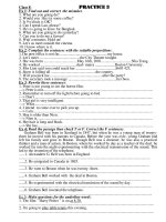
To create a new theme, go to the 'View' menu and select 'New Theme' – as illustrated below.
From the resulting menu it is possible to create either a point; line; or polygon theme (see
below). We will begin by creating a 'Point' theme.
You will then be asked for the location you wish to create the new theme in and the name of
the resulting theme. Select the following location:- 'c:\point_trial'. The theme has now been
created but currently holds no information. The theme's drawing Point_trial.shp check box has a
Practice 3: Inputting Geographical Data ERS 120: Principles of GIS
N.D. Bình 14/59
dashed line around it ( ) - indicating that it is in editing mode.
To activate the pull down list hold the mouse pointer over the small arrow in the
bottom right-hand comer and hold down the mouse-button.
From the 'Drawing tool palette' that appears (see diagram to the right) make sure
the 'Draw Point' tool is selected. Now click within the view to create a point feature.
To add attribute data to the points - click on the 'Open Theme Table' button ( ).
When you create a new point feature, a corresponding new record is automatically
added to the themes feature attribute table. While editing a theme - the table is also
in edit mode and so we can add data at anytime. Give your points unique IDs (label
them numerically, 1 2 3 etc.). Once you have finished close the table window
and return to the main view.
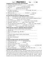
We have now finished creating our point theme, so we can stop editing. Go to the
'Theme' menu and select 'Stop Editing' (see diagram below). Save your editing. Note
how the last created point becomes highlighted - click on the 'Clear Selected
Features' button ( ) to nullify this. Note if you now go back to the 'Theme' menu
the 'Stop Editing' button has become' Start Editing'. We do not wish to make any
new changes to out theme so we can leave the 'Theme' menu (click off the menu area).
Step 2 Line data
Now repeat the processes descried in step one to create the following line theme' c:\line_trial'.
Note how the 'Drawing tool palette' automatically selects the 'Draw Line' function. Click the mouse
button over the view and then move the mouse to a new location - a line will appear, click the
mouse again and repeat the process. To end a line double click the mouse button. Practise
creating lines. When finished , you may want to use the 'Pan' tool to move the viewable area
to a new, empty location.
Practice 3: Inputting Geographical Data ERS 120: Principles of GIS
N.D. Bình 15/59
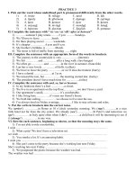
Right click anywhere within the view and hold the mouse button - the editing popup is now
displayed (see diagram below). From here snapping options can be chosen - select 'Enable
General Snapping' and a new tool called 'Snap' ( becomes available.
Now click and hold the left mouse button anywhere in the view - when you now move the
mouse a graphic circle will be drawn. This circle represents the extent that a line will be 'snapped'
to another line. Set the snapping distance to approximately 3 cm on your display. When you now
draw a line the graphic circle will be attached to the end of the line.
Draw a line as depicted below and then begin to construct another as illustrated. Normally
these lines would not be connected together but because the second line lies within the snapping
extent ArcView automatically joins the two lines together. Experiment with the snapping
environment.
If at any time you want to delete the last waypoint created for a line bring up the editing popup
menu and select 'Delete Last Point'. Try it. Remember to end editing mode (Theme - Stop
Editing) once you have finished and save your edits.
Step 3 Polygon data
Repeat the processes descried in step one to create a new polygon theme - 'c:\poly_trial'.
Your polygons can be simple rectangles (use the tool, click and hold the mouse button and
then move to a new location before releasing the button), circles -use the same methodology
as for rectangles), or irregular . Note you change the type of polygon by initiating the 'Drawing
tool palette' (hold the left mouse button while over the current drawing tool (for example ).
Irregular polygons are created in the same manner as lines, whereby the user clicks to assign
way points and double clicks when finished. Try and create a mixture of polygons.
You can alter your polygons using the 'Split' and the 'Adjacent' functions found within
drawing tool palette. Samples of what they do are illustrated below - experiment with them for
yourself.
Practice 3: Inputting Geographical Data ERS 120: Principles of GIS
N.D. Bình 16/59
Again general snapping can be used to create polygons that share mutual boundaries (similar
to the adjacent tool). Experiment by creating a mosaic of polygons that fill the view, similar to that
displayed below. Once you have finished you may wish to delete the themes you have created to
save space - note you will have to delete them from your view (Edit - Delete Themes) before
deleting the actual files is possible.
Step 4 Digitising using real data
The majority of themes that require digitising with usually require raster to vector conversion.
Here we will rectify a pre-scanned image of Sheffield and then digitize certain features.
To geo-reference the image - minimise ArcView, open 'Notepad' (found within the 'Start
menu', 'Programs' and then 'Accessories') and type the following:-
11.48373502851803
0.0
0.0
-11.48373502851803
433091
Practice 3: Inputting Geographical Data ERS 120: Principles of GIS
N.D. Bình 17/59
390912
Save the file as 'c:\temp\backdrop'. However, the file will automatically be saved as a text
document but we require it to have a *jpgw extension. So, go to 'Command Prompt' for MS DOS
('Start menu' then 'Programs') and type the following:-
cd\
cd temp
rename c:\temp\backdrop.txt backdrop.jpgw
exit
5
Return to ArcView, to make a jpeg image visible we firstly have to load the appropriate
extension. Go to the 'File' menu and select 'Extensions ', check the box next to the 'JPEG (JFIF)
Image Support' extension. Now open the image ('add theme') 'c:\temp\backdrop.jpg',
remembering that it is an image data source that we require. To check if the image is correctly
rectified open up the feature theme 'c:\temp\roads.shp' the roads should align with those within
the backdrop.
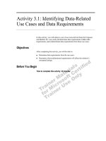
Digitise the railway within the backdrop by creating a new line theme call it 'c:\airway.shp' .
Open up the theme ' c:\temp\wards.shp'. Digitise the polygons and points as separate themes
(entitled 'c :\wards.shp' and 'c:\points.shp' respectively). Overlay all the relevant vector shape
themes (railway, roads, points and wards) with the backdrop image to display the finished dataset
(you should have something like that shown below). Once finished, there is no need to keep any
of the files you have created.
This week you have learnt how to create graphical features and also how to perform basic
'heads-up' digitising within ArcView. When these techniques are combined with the creation of
tabular attribute data (as demonstrated in last practical sessions) it is possible to create a whole
database to fulfill your data requirements.
Last modified: Oct 25, 2009
ERS 120: Introduction to Geographic Information Systems /