PIC assembly language for the complet programer
Bạn đang xem bản rút gọn của tài liệu. Xem và tải ngay bản đầy đủ của tài liệu tại đây (153.83 KB, 34 trang )
PIC Assembly Language for the
Complete Beginner
Michael A. Covington
Artificial Intelligence Center
The University of Georgia
Athens, Georgia 30602-7415
/>This article appeared in Electronics Now Magazine in 1999 and is
reprinted here by permission. Some web addresses have been up-
dated but the content has not; you will find that MPLAB, for instance,
now looks somewhat different.
You may print out this article for personal use but not for further pub-
lication.
Copyright
c
1999 Gernsback Publications, Inc.
Copyright
c
1999, 2004 Michael A. Covington.
These days, the field of electronics is divided into “haves” and “ have-
nots” – people who can program microcontrollers a n d people who can’t.
If you’re one of the “have-nots,” this article is for you.
1
Microcontrollers are one-chip computers designed to control other equip -
ment, and almost all electronic equipment now uses them. The average
American home now contains about 100 computers, almost all of which
are microcontrollers hidden within app liances, clocks, thermostats, and
even automobile engines.
Although some microcontrollers can be programmed in C or BASIC,
you need a ssembly language to get the best results with the least expensive
micros. The reason is that assembly language lets you specify the exact
instructions that the CPU will follow; you can control exactly how much
time and memory each step of the program will take. On a tiny computer,
this can be important. What’s more, if you’re not already an experienced
programmer, you may well find that assembly language is s impler than
BASIC or C. In many ways it’s more like designing a circuit than writing
software.
The trouble with assembly language is that it’s different for each kind
of CPU. The re’s one assembly language for Pentiums, a nother for PIC mi-
crocontrollers, still another for Motorola 68000s, and so forth. There are
even slight differences from one model of PIC to another. And that leads
to a serious problem – each assembly-language manual seems to assume
that you already know the assembly language for some other processor!
So as you look from one manual to another in puzzlement, there’s no way
to get started.
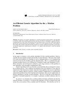
That’s the problem this article will address. I won’t teach you all of
PIC assembly language, just enough to get you started. For concreteness,
I’ll use just one processor, the PIC16F84. To be very precise, I’ll use the
2
PIC16F84-04P, which operates up to 4 MHz and is housed in a plastic DIP
package.
1
This is a product of Microchip, Inc. (Chandler, Arizona), and it’s
closely related to the rest of the PIC family – which, however, I’ll ignore to
prevent confusion.
To do the experiments described in this article, you’ll need one or more
PIC16F84-04P chips; we strongly recommend having more than one so
you can rule out a damaged PIC if your circuit doesn’t work. You’ll also
need the other parts for the circuits you want to build (see the schematics).
And you’ll need a PC-compatible personal computer, the MPASM assem-
bler software (which you can download from ),
and a PIC programmer such as Ramsey Ele ctronics’ “PICPRO-1” or the
NOPPP programmer published in this magazine, September 1998, and
described at The PIC16F8X
data sheet, actually a 122-page manual, will also come in handy; it’s called
PIC16F8X because it covers both PIC16F84 and PIC14F83, and you can
download it or request a printed copy from Microchip.
1 PART 1 - MEET THE PIC
1.1 What’s insi de a PIC?
Figure 1 shows the pinout of the PIC16F84, and Figure 2 shows the most
important parts inside. The PIC is a tiny but complete computer. It has a
CPU (central processing unit), program memory (PROM), working mem -
1
Note added 2004: The 10- MHz version is now more common and will work in all the
same circuits.
3
1
2
3
4
5
6
18
17
16
15
14
13
A2
A3
A4
MCLR
GND
B0 B7
V+
O2
O1
A0
A1
12
11
10
7
8
9
B1
B2
B3 B4
B5
B6
PIC16F84
Figure 1: Pinout of PIC16F84.
ory (RAM), a nd two input-output ports.
The CPU is, of course, the “brain” of the computer. It reads and exe-
cutes instructions from the program memory. As it does so, it can store and
retrieve data in working memory (RAM). Some CPUs make a distinction
between “registers” located within the CPU a nd “RAM” located outside
it; the PIC doesn’t, and its general-purpose working RA M is also known
as “file registers.” On the ’F84, there are 68 bytes of general-purpose RAM,
located at ad dresses hex 0C to hex 4F.
Besides the general-purpose memory, there is a special “working regis-
ter” or “W register” where the CPU holds the data it’s working on. There
are also several special-function registers each of which controls the oper-
4
ation of the PIC in some way.
The program memory of the ’F84 consists of flash EPROM; it can be
recorded and erased electrically, and it retains its contents when pow-
ered off. Many other PICs require ultraviolet light for erasure and are not
erasable if you buy the cheaper version without the quartz window. The
’F84, however, is always erasable a nd reprogrammable.
There are two input-output ports, port A and port B, and each pin of
each p ort can be set individually as an input or an output. The bits of
each port are numbered, starting at 0. In output mode, bit 4 of port A has
an open collector (or rather open drain); the rest of the outputs are regular
CMOS. (Working with microcontrollers, you have to remember details like
this; there’s no programming language or operating system to hide the
details of the hardware from you.) The CPU treats each port as one 8-bit
byte of data e ven though only five bits of port A are actually brought out
as pins of the IC.
W REGISTER
O1 O2
14-BIT BUS
8-BIT BUS
B0
SPECIAL
FUNCTION
REGISTERS
PROGRAM
MEMORY
(FLASH EPROM)
FILE
REGISTERS
(RAM)
CPU
CLOCK
OSCILLATOR
PORT B
B1B2B3B4B5B6B7
A0A1A2A3
CMOS INPUTS AND OUTPUTS
PORT A
A4
Figure 2: Main components of the PIC16F84.
5
PIC inputs are CMOS-compatible; PIC outputs can drive TTL or CMOS
logic chips. Each output pin can source or sink 20 mA as long as only one
pin is doing so at a time. Further information about electrical limits is
given in the PIC16F84 data sheet.
The ’F84 also has some features we won’t be using, including an EEP-
ROM for long-term storage of data, an onboard timer-counter module,
and optional pull-up resistors on port B.
1.2 Power and clock requirements
The PIC16F84 requires a 5-volt supply; actually, any voltage from 4.0 to
6.0 volts will do fine, so you can run it from three 1.5-volt cells. Figure
3 shows several power-supply options. The PIC consumes only 1 mA –
even less, a t low clock speeds – but the power supply must also provide
the current flowing through LEDs or other high-current devices that the
PIC may be driving. Thus, the last circuit, with the Zener diode, is only
for PICs that aren’t driving LEDs.
All four power supply circuits rely on a 0 . 1-µF capacitor from pin 14
(V+) to ground, mounted close to the PIC, to protect the PIC and a d ja-
cent components from electrical noise. This capacitor should be present
no matter how clea n you think your DC supply is.
The MCL R pin is normally connected to V+ through a 10k resistor.
Grounding it momentarily will clear RAM and reset the PIC. If your power
supply voltage comes up slowly, the PIC may start up in a confused state;
in that case you should add a normally-open reset button from MCLR to
ground.
6
IN OUT
GND
7805
OR 78L05
1.5V
ON/
OFF
1.5V 1.5V
ON/
OFF
1N4001
+7V
TO 20V
+4.5V
+5.4V
+5.0V
6V OR
FOUR 1.5V
IN SERIES
1K
1N4733A
(5.1V)
+5.1V
(SEE
NOTE)
+6V
TO 20V
4
5 14
MCLR
GND V+
PIC16F84
10K
0.1
µF
+4V TO 6V
Figure 3: Some ways to power a PI C. The last one is only for a PIC that is
not powering an LED or other high-current load.
7
Like any CPU, the PIC needs a clock – an oscillator to control the speed
of the CPU and step it through its operations. The maximum clock fre-
quency of the PIC16F84-04P is, a s already noted, 4 MHz. There is no lower
limit. Low clock frequencies save power and reduce the amount of count-
ing the PIC has to do when timing a slow operation. At 30 kHz, a PIC can
run on 0. 1 mA.
Figure 4 shows the most popular clock circuits. The clock signal can be
fed in from an external source, or you can use the PIC’s on-board oscilla-
tor with either a crystal or a resistor and capacitor. Crystals are preferred
for high accuracy; 3.58-MHz crystals, mass-produced for color TV circuits,
work well and are very cheap. The resistor-capacitor oscillator is cheaper
yet, but the frequency is somewhat unpredictable; don’t use it if your cir-
cuit needs to keep time accurately.
2 PART 2 - YO UR FIRST PRO GRAM
2.1 Assembly language
A PIC spends its time reading instructions from the program memory, one
after another, and doing whatever these instructions say. Each instruction
consists of 14 bits. If you could see the bits as binary ones and zeroes, the
program in Figure 5 would look like this:
11000000000000
00000001100110
11000000000001
8
EXTERNAL CLOCK
NC
16
15
O2
O1
PIC16F84
16
15
O2
O1
PIC16F84
2-4
MHz
22
pF
22
pF
16
15
O2
O1
PIC16F84
NC
100
pF
+5V
3.3K (1.5 MHz)
10K (600 kHz)
100K (100 kHz)
Figure 4: Three ways to provide the clock signal to a PI C.
9
; File TURNON.ASM
; Assembly code for PIC16F84 microcontroller
; Turns on an LED connected to B0.
; Uses RC oscillator, about 100 kHz.
; CPU configuration
; (It’s a 16F84, RC oscillator,
; watchdog timer off, power-up timer on.)
processor 16f84
include <p16f84.inc>
__config _RC_OSC & _WDT_OFF & _PWRTE_ON
; Program
org 0 ; start at address 0
; At startup, all ports are inputs.
; Set Port B to all outputs.
movlw B’00000000’ ; w := binary 00000000
tris PORTB ; copy w to port B control reg
; Put a 1 in the lowest bit of port B.
movlw B’00000001’ ; w := binary 00000001
movwf PORTB ; copy w to port B itself
; Stop by going into an endless loop
fin: goto fin
end ; program ends here
Figure 5: A complete PIC assembly-language program.
10
00000010000110
10100000000100
The earliest computers were programmed by technicians writing binary
codes just like this. As you can see, though, binary codes are very hard for
human beings to read or write because they’re completely arbitrary; they
look like gibberish.
Another reason binary codes are hard to write is that many of them
refer to locations in memory. For instance, a “go to” instruction will have
to say wha t memory address to jump to. Programming would be much
easier if you could label a location in the program and have the computer
figure out its address.
For both of these reasons, assembly language was invented over forty
years ago. Or, to be more precise, many assembly languages have been in-
vented, one for each type of CPU. What a ssembly languages have in com-
mon is that the instructions are abbreviated by readable codes (mnemonics)
such as GOTO and locations can be represented by programmer-assigned
labels. For example, in assembly language, the binary instructions just
mentioned would be:
movlw B’00000000’
tris PORTB
movlw B’00000001’
movwf PORTB
fin: goto fin
In English: Put the bit pattern 000000 00 into the W register and copy it to
the tri-state control register for p ort B, thereby setting up port B for output;
11
then put 00000001 into W and copy it to port B itself; and finally stop the
program by going into an endless loop.
2.2 Program layout
Figure 5 shows a complete, ready-to-assemble program. Look closely at its
layout. The semicolon (;) is the comment marker; the computer ignores
everything after the semicolon on each line. Much of the program consists
of comments; that’s as it should be, because al though it’s not as bad as
binary code, a ssembly language is still relatively hard to read.
Each instruction is divided into three parts, the label, the opcode (opera-
tion code or instruction code), and the operand (also called argument). For
example, in the line
fin: goto fin
the label is fin: (with a colon), the opcode is goto, and the operand is
fin.
The label, opcode, and operand are separated by spaces. The assembler
doesn’t care how many spaces you use; one is enough, but most program-
mers use additional spaces to make their instructions line up into neat
columns.
If there’s no label, there must be at least one blank before the opcode,
or the assembler will think the opcode is a label. Although current PIC
assemblers can often recover from this kind of error, it is an error, and
other assemblers aren’t so tolerant.
12
2.3 Assembling a program
A computer “assembles” the assembly-language program into the binary
instructions, which, for brevity, are actually written in hexadecimal (more
about this shortly) and stored on what is called a .HEX file. Some comput-
ers run their own assemblers, but the PIC is far too small for that; instead,
you’ll type and assemble your PIC programs on a DOS or Windows PC.
Then you’ll d ownload the .HEX file into a PIC using a PIC programmer
and its associated software.
The program in Figure 5 does one very simple thing – it turns on an
LED connected to pin B0. Figure 6 shows the circuit needed to try this
program out. You can also use the circuit in Figure 10 or the demonstra-
tion board included with the Ramsey Electronics PICPRO-1. Admittedly,
turning on one LED is not a great feat of computation, but it’s enough to
show that the PIC works.
To assemble this program, you’ll need MPASM, the free PIC assem-
bler downloadable from . You also need the file
P16F84.INC, which comes with MPASM and tells the assembler the par-
ticulars of the ’F84 as opposed to the numerous other varieties of PIC. You
won’t need the other .IN C files also included with the assembler.
What you d o is type your program onto a file with a name ending in
.ASM, using Windows Notepad, DOS EDIT, or any other text editor. Don’t
use a word processor unless you are sure you can save your file as pla in
ASCII.
Then run MPASM from a DOS prompt (a DOS box under Windows is
OK). If your program file is named turnon.asm, type the command
13
1
2
3
4
5
6
18
17
16
15
14
13
A2
A3
A4
MCLR
GND
B0 B7
V+
O2
O1
A0
A1
12
11
10
7
8
9
B1
B2
B3 B4
B5
B6
IC1
PIC16F84
R2
100K
C1
0.1
µF
C2
100
pF
R1
10K
+5V
R3
1K
LED
Figure 6: Circuit for simple program that turns on an LED (Fig. 5).
14
Figure 7: Running MPASM, the PIC assembler.
15
mpasm turnon.asm
and Figure 7 shows what you’ll see on the screen.
What MPASM is telling you is that it assembled your .ASM file, gener-
ating one warning message (which is unimportant – more about this later)
and no error messages. The results consists of a .HEX file containing the
assembled instructions and a .LST file containing a detailed program list-
ing with error messages. If the program contained serious errors, no .HEX
file would be generated and you should study the .LST file to see what
went wrong.
MPASM is the simple way to go. Microchip also gives away a devel-
opment environment called MPLAB (Figure 8) that contains an assembler
plus a simulator so you can make your PC pretend to be a PIC and actually
see your program run. MPLAB is very useful but its operation is beyond
the scope of this article. See />for some tips.
Now that you have a .HEX file , you have to get it into the PIC. This
is done with a programmer such as Microchip’s “Picstart Plus” or the
NOPPP programmer featured in Electronics Now, September 1998, and now
marketed by Ramsey Electronics as PICPRO-1. On your PC, you run what-
ever software your programmer requires and follow the instructions.
Finally, put the programmed PIC into the circuit (handling it carefully
to prevent static dam age) and apply 5 volts. The LED should turn on.
There – you’ve made a PIC do something.
16
Figure 8: MPLAB, the PIC development environment.
17
2.4 How the program works
Now look back at Figure 5 and consider the program in detail. More than
half of what you see there consists of comments; everything after the first
semicolon (;) in each line is a comment ignored by the computer.
The program starts with a number of pseudo instructions, commands
that give information to the assembler but are not translated into machine
instructions. The first pseudo instruction,
processor PIC16F84
tells the assembler what kind of CPU you’re using. It’s immediately fol-
lowed by another instruction,
include <p16f84.inc>
telling the assembler to read the file P16F84.INC, which contains a lot more
pseudo instructions giving the memory addresses of the ports and other
particulars of this CPU.
Next comes the __config macro instruction:
__config _RC_OSC & _WDT_OFF & _PWRTE_ON
Notice that there are two underscore marks at the beginning of __config.
This instruction specifies some configuration settings to be programmed
into the PIC. It says you’re using an RC oscillator (resistor and capacitor,
not crystal); the watchdog timer is off; and the power-up timer is on. The
power-up timer imposes a slight delay at startup to give the 5-volt supply
time to stabilize. The watchdog timer is a built-in device for rebooting the
PIC every 18 milliseconds; some programs use this to protect themselves
18
from endless loops, but it’s very important to turn it off if you’re not using
it, or your program will keep restarting itself at inopportune moments.
The last pseudo instruction is
org 0
which means, “The next instruction should go at address 0 in program
memory.” That is, you’re telling the assembler where to start. Then come
the program instructions, and finally the pseudo instruction
end
which tells the assembler that the program is over. Unlike END in BASIC,
end in assembly language does not tell the program to stop running.
2.5 What the instructions do
Now look at the actual CPU instructions in the program, namely:
movlw B’00000000’
tris PORTB
movlw B’00000001’
movwf PORTB
fin: goto fin
What the program needs to do is set up port B for output, place a 1 into
the lowest bit of port B (causing pin B0 to go high), and stop. Consider
the last of these first. How do you stop a program? Not by making the
processor go dead, because then the output at B0 would disappear and
19
the LED would turn off. Nor by e xiting to the operating system, because
there isn’t an operating system. Your program has the PIC all to itself.
The way you stop this program is by putting it in an endless loop.
That’s accomplished by the instruction
fin: goto fin
which simply jumps back to itself, over and over.
Now look at the previous step. How do you place a 1 in the lowest
bit of port B? From the CPU’s viewpoint, port B is an 8-bit register and
we want to place binary 00000001 in it. But there is no CPU instruction
to place a specified value (a “literal”) directly into a port. Instead, the
program pla ces 00000001 into the W register using a movlw instruction
(“move literal to W”) a nd then copies W to port B using a movwf instruc-
tion (“move W to file register”).
Note that in assembly language, “move” always means “copy.” That
is, every “move” instruction actually copies data from one place to another,
leaving the original unchanged. This is true of all the assembly languages
I’ve seen, regardless of the kind of CPU.
Note also that in PIC assembly language, the name of port B is PORTB
(all capitals), not portb (lower case). This name was defined in P16F84.INC.
MPLAB will recognize both names but the assembler won’t – a possible
source of confusion.
In order for port B to work as intended, it has to be set up as an output
port. A ctually, each of its eight bits can be set as input or output, inde-
pendently of the others, but in this program, all eight bits are set to out-
20
put. This is done by zeroing the corresponding bits in the TRISB special-
function register.
2.6 Deprecated instructions – Error messages to ignore
And here we run into a “deprecated instruction,” a instruction that works
perfectly well but which the assembler tells us not to use. That is tris,
the instruction that copies W into that special function register. To set up
port B for output, we use the instructions
movlw B’00000000’
tris PORTB
and the second of these al wa ys generates a warning message.
The reason for the warning message is that some other PICs lack the
tris instruction, and in the interest of program portability, Microchip,
Inc., would like us not to use it. Instead, they want us to do something a
good bit more complicated, involving switching over to a different bank
of registers, then addressing the TRISB register by its address.
That’s their preference, but it need not be yours or mine. The tris in-
struction is fully supported on the ’F84; there’s nothing wrong with using
it; it is not unreliable or risky in any way. It just generates an error message
you have to ignore. The same is true of the option instruction, which lets
you set some CPU configuration options without switching register banks.
21
3 PART 3 - MAKING THE PIC CO MPUTE
3.1 A more elaborate program
Figure 9 shows a more elaborate PIC program that makes eight LEDs blink
on, one at a time, in a “chaser” sequence. The sequence reverses direction
when you change the logic level on pin A0.
Figure 10 is the circuit for running it. You can make this circuit out of
the demo board that comes with the Ramsey PICPRO-1 if you add a switch
or jumper so that you can connect pin 17 (A0) to either V+ or ground. With
this program, d o not leave pin 17 floating; it’s a CMOS input and will pick
up noise. Also, do not modify the program to light more than one LED at
a time; the PIC can’t output that much power.
3.2 Describing bit patterns
Before going any further, we need to lay some groundwork. Each PIC file
register, i/o port, and memory address consists of one 8-bit byte. Thus,
any PIC assembly-language program is going to contain a lot of groups of
eight bits. There are three main ways to describe a bit pattern: in binary,
in hexadecimal, or in decimal.
Obviously, you can describe a bit pattern by writing out the bits them-
selves, such as B’00011101’. In PIC assembly la nguage, the B and quotes
are required. The lowest-numbered bit comes last; if you output B’00000001’
on port B, pin B0 will go high, but B’10000000’ will make pin B7 go
high.
You may ha ve been told that computers treat everything as numbers.
22
; File CHASER.ASM
; Blinks LEDs on outputs (Port B) in a rotating pattern.
; Reverses direction if port A, Bit 0, is high.
processor 16f84
include <p16f84.inc>
__config _RC_OSC & _WDT_OFF & _PWRTE_ON
; Give names to 2 memory locations (registers)
J equ H’1F’ ; J = address hex 1F
K equ H’1E’ ; K = address hex 1E
; Program
org 0 ; start at address 0
; Set Port B to output and initialize it.
movlw B’00000000’ ; w := binary 00000000
tris PORTB ; copy w to port B control reg
movlw B’00000001’ ; w := binary 00000001
movwf PORTB ; copy w to port B itself
bcf STATUS,C ; clear the carry bit
; Main loop. Check Port A, Bit 0, and rotate either left
; or right through the carry register.
mloop:
btfss PORTA,0 ; skip next instruction if bit=1
goto m1
rlf PORTB,f ; rotate port B bits to left
goto m2
m1:
rrf PORTB,f ; rotate port B bits to right
m2:
; Waste some time by executing nested loops
movlw D’50’ ; w := 50 decimal
movwf J ; J := w
jloop: movwf K ; K := w
kloop: decfsz K,f ; K := K-1, skip next if zero
goto kloop
decfsz J,f ; J := J-1, skip next if zero
goto jloop
goto mloop ; do it all again
end ; program ends here
Figure 9: A more elaborate PIC program.
23
1
2
3
4
5
6
18
17
16
15
14
13
A2
A3
A4
MCLR
GND
B0 B7
V+
O2
O1
A0
A1
12
11
10
7
8
9
B1
B2
B3 B4
B5
B6
IC1
PIC16F84
R2
100K
R1
10K
+5V
R3-
R10
1K
C2 100 pF
C1 0.1 µF
LED1-
LED10
(RED OR
GREEN)
S1
Figure 10: With program in Fig. 9, LEDs flash in chaser sequence; switch
S1 reverses direction.
24
That’s not true; computers treat everything as bit p atterns. Nonetheless,
one common way of interpreting bit patterns is to take them as bina ry
numbers. When this is done, you can write the same number more con-
cisely in another base (radix). For example, binary 00000110 is 1 ×4 + 1 ×2,
or 6 in ordinary (decimal) notation. (I n this context “decimal” does not im-
ply that there are digits to the right of the point.) Converted to decimal,
the 25 6 possible 8-bit bytes, B’00000000’ to B’11111111’, range from
0 to 2 55.
It turns out to be even more convenient to convert binary numbers to
base 16 (hexadecimal, or hex for short). In hex, there are sixteen digits, 0,
1, 2, 3, 4, 5, 6, 7, 8, 9, A, B, C, D, E, and F. As you might guess, A means 10,
B means 11, a nd so forth up to F = 15. Thus FF means fifteen sixteens plus
fifteen ones, or 255 (binary 11111111).
The reason hex is used is that each hex digit corresponds to four bi-
nary digits. If binary 0110 equals hex 6, then binary 01100110 equals hex
66. With some practice, you can learn to do hex-binary conversions in
your head. Many scientific calculators can interconvert hex, binary, and
decimal. Figure 11 is a complete conversion chart for all possible 8-bit
patterns.
3.3 A word of warning
In PIC assembly language you should normally spe cify the base of every
number you write, such as B’11111111’, D’255’, or H’FF’. If you write
numbers without the quotes and base indication, they will normally be
taken as hex, but it’s best to be safe. If you write a character between
25