một bộ công cụ để mô hình hóa và mô phỏng các môi trường điện toán đám mây và đánh giá các thuật toán trích lập dự phòng tài nguyên
Bạn đang xem bản rút gọn của tài liệu. Xem và tải ngay bản đầy đủ của tài liệu tại đây (539.28 KB, 28 trang )
SOFTWARE – PRACTICE AND EXPERIENCE
Softw. Pract. Exper. 2011; 41:23–50
Published online 24 August 2010 in Wiley Online Library (wileyonlinelibrary.com). DOI: 10.1002/spe.995
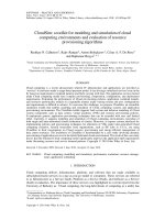
CloudSim: a toolkit for modeling and simulation of cloud
computing environments and evaluation of resource
provisioning algorithms
Rodrigo N. Calheiros
1
, Rajiv Ranjan
2
, Anton Beloglazov
1
,C
´
esar A. F. De Rose
3
and Rajkumar Buyya
1, ∗, †
1
Cloud Computing and Distributed Systems (CLOUDS) Laboratory, Department of Computer Science and Software
Engineering, The University of Melbourne, Australia
2
School of Computer Science and Engineering, The University of New South Wales, Sydney, Australia
3
Department of Computer Science, Pontifical Catholic University of Rio Grande do Sul, Porto Alegre, Brazil
SUMMARY
Cloud computing is a recent advancement wherein IT infrastructure and applications are provided as
‘services’ to end-users under a usage-based payment model. It can leverage virtualized services even on the
fly based on requirements (workload patterns and QoS) varying with time. The application services hosted
under Cloud computing model have complex provisioning, composition, configuration, and deployment
requirements. Evaluating the performance of Cloud provisioning policies, application workload models,
and resources performance models in a repeatable manner under varying system and user configurations
and requirements is difficult to achieve. To overcome this challenge, we propose CloudSim: an extensible
simulation toolkit that enables modeling and simulation of Cloud computing systems and application
provisioning environments. The CloudSim toolkit supports both system and behavior modeling of Cloud
system components such as data centers, virtual machines (VMs) and resource provisioning policies.
It implements generic application provisioning techniques that can be extended with ease and limited
effort. Currently, it supports modeling and simulation of Cloud computing environments consisting of
both single and inter-networked clouds (federation of clouds). Moreover, it exposes custom interfaces for
implementing policies and provisioning techniques for allocation of VMs under inter-networked Cloud
computing scenarios. Several researchers from organizations, such as HP Labs in U.S.A., are using
CloudSim in their investigation on Cloud resource provisioning and energy-efficient management of
data center resources. The usefulness of CloudSim is demonstrated by a case study involving dynamic
provisioning of application services in the hybrid federated clouds environment. The result of this case study
proves that the federated Cloud computing model significantly improves the application QoS requirements
under fluctuating resource and service demand patterns. Copyright q 2010 John Wiley & Sons, Ltd.
Received 3 November 2009; Revised 4 June 2010; Accepted 14 June 2010
KEY WORDS
: Cloud computing; modelling and simulation; performance evaluation; resource manage-
ment; application scheduling
1. INTRODUCTION
Cloud computing delivers infrastructure, platform, and software that are made available as
subscription-based services in a pay-as-you-go model to consumers. These services are referred
to as Infrastructure as a Service (IaaS), Platform as a Service (PaaS), and Software as a Service
(SaaS) in industries. The importance of these services was highlighted in a recent report from the
University of Berkeley as: ‘Cloud computing, the long-held dream of computing as a utility has
∗
Correspondence to: Rajkumar Buyya, Cloud Computing and Distributed Systems (CLOUDS) Laboratory, Department
of Computer Science and Software Engineering, The University of Melbourne, Australia.
†
E-mail:
Copyright q 2010 John Wiley & Sons, Ltd.
24 R. N. CALHEIROS ET AL.
the potential to transform a large part of the IT industry, making software even more attractive as
a service’ [1].
Clouds [2] aim to power the next-generation data centers as the enabling platform for dynamic
and flexible application provisioning. This is facilitated by exposing data center’s capabilities as a
network of virtual services (e.g. hardware, database, user-interface, and application logic) so that
users are able to access and deploy applications from anywhere in the Internet driven by the demand
and Quality of Service (QoS) requirements [3]. Similarly, IT companies with innovative ideas for
new application services are no longer required to make large capital outlays in the hardware and
software infrastructures. By using clouds as the application hosting platform, IT companies are
freed from the trivial task of setting up basic hardware and software infrastructures. Thus, they
can focus more on innovation and creation of business values for their application services [1].
Some of the traditional and emerging Cloud-based application services include social networking,
web hosting, content delivery, and real-time instrumented data processing. Each of these appli-
cation types has different composition, configuration, and deployment requirements. Quantifying
the performance of provisioning (scheduling and allocation) policies in a real Cloud computing
environment (Amazon EC2 [4], Microsoft Azure [5], Google App Engine [6]) for different appli-
cation models under transient conditions is extremely challenging because: (i) Clouds exhibit
varying demands, supply patterns, system sizes, and resources (hardware, software, network);
(ii) users have heterogeneous, dynamic, and competing QoS requirements; and (iii) applications
have varying performance, workload, and dynamic application scaling requirements. The use of
real infrastructures, such as Amazon EC2 and Microsoft Azure, for benchmarking the application
performance (throughput, cost benefits) under variable conditions (availability, workload patterns)
is often constrained by the rigidity of the infrastructure. Hence, this makes the reproduction of
results that can be relied upon, an extremely difficult undertaking. Further, it is tedious and time-
consuming to re-configure benchmarking parameters across a massive-scale Cloud computing
infrastructure over multiple test runs. Such limitations are caused by the conditions prevailing in the
Cloud-based environments that are not in the control of developers of application services. Thus,
it is not possible to perform benchmarking experiments in repeatable, dependable, and scalable
environments using real-world Cloud environments.
A more viable alternative is the use of simulation tools. These tools open up the possibility
of evaluating the hypothesis (application benchmarking study) in a controlled environment where
one can easily reproduce results. Simulation-based approaches offer significant benefits to IT
companies (or anyone who wants to offer his application services through clouds) by allowing
them to: (i) test their services in repeatable and controllable environment; (ii) tune the system
bottlenecks before deploying on real clouds; and (iii) experiment with different workload mix and
resource performance scenarios on simulated infrastructures for developing and testing adaptive
application provisioning techniques [7].
Considering that none of the current distributed (including Grid and Network) system simulators
[8–10] offer the environment that can be directly used for modeling Cloud computing environ-
ments, we present CloudSim: a new, generalized, and extensible simulation framework that allows
seamless modeling, simulation, and experimentation of emerging Cloud computing infrastructures
and application services. By using CloudSim, researchers and industry-based developers can test
the performance of a newly developed application service in a controlled and easy to set-up environ-
ment. Based on the evaluation results reported by CloudSim, they can further finetune the service
performance. The main advantages of using CloudSim for initial performance testing include:
(i) time effectiveness: it requires very less effort and time to implement Cloud-based application
provisioning test environment and (ii) flexibility and applicability : developers can model and test
the performance of their application services in heterogeneous Cloud environments (Amazon EC2,
Microsoft Azure) with little programming and deployment effort.
CloudSim offers the following novel features: (i) support for modeling and simulation of large-
scale Cloud computing environments, including data centers, on a single physical computing
node; (ii) a self-contained platform for modeling Clouds, service brokers, provisioning, and allo-
cation policies; (iii) support for simulation of network connections among the simulated system
Copyright q 2010 John Wiley & Sons, Ltd. Softw. Pract. Exper. 2011; 41:23–50
DOI: 10.1002/spe
CLOUDSIM: A TOOLKIT 25
elements; and (iv) facility for simulation of federated Cloud environment that inter-networks
resources from both private and public domains, a feature critical for research studies related to
Cloud-Bursts and automatic application scaling. Some of the unique features of CloudSim are:
(i) availability of a virtualization engine that aids in the creation and management of multiple,
independent, and co-hosted virtualized services on a data center node and (ii) flexibility to switch
between space-shared and time-shared allocation of processing cores to virtualized services. These
compelling features of CloudSim would speed up the development of new application provisioning
algorithms for Cloud computing.
The main contributions of this paper are: (i) a holistic software framework for modeling Cloud
computing environments and performance testing application services and (ii) an end-to-end Cloud
network architecture that utilizes BRITE topology for modeling link bandwidth and associated
latencies. Some of our findings related to the CloudSim framework are: (i) it is capable of supporting
a large-scale simulation environment with little or no overhead with respect to initialization over-
head and memory consumption; (ii) it exposes powerful features that could easily be extended
for modeling custom Cloud computing environments (federated/non-federated) and application
provisioning techniques (Cloud-Bursts, energy conscious/non-energy conscious).
The remainder of this paper is organized as follows: first, a g eneral description about Cloud
computing, existing models, and their layered design is presented. This section ends with a brief
overview of existing state-of-the-art in distributed (grids, clouds) system simulation and modeling.
Following that, comprehensive details related to the architecture of the CloudSim framework are
presented. Section 4 presents the overall design of the CloudSim components. Section 5 presents a
set of experiments that were conducted for quantifying the performance of CloudSim in successfully
simulating Cloud computing environments. Section 6 gives a brief overview of the projects that
are using or have used CloudSim for research and development. Finally, the paper ends with brief
conclusive remarks and a discussion on future research directions.
2. BACKGROUND
This section presents the background information on various elements that form the basis for
architecting Cloud computing systems. It also presents the requirements of elastic or malleable
applications that need to scale across multiple, geographically distributed data centers that are
owned by one or more Cloud service providers. The CloudSim framework aims to ease-up and
speed the process of conducting experimental studies that use Cloud computing as the application
provisioning environments. Note that, conducting such experimental studies using real Cloud
infrastructures can be extremely time-consuming due to their sheer scale and complexity.
2.1. Cloud computing
Cloud computing can be defined as ‘a type of parallel and distributed system consisting of a
collection of inter-connected and virtualized computers that are dynamically provisioned, and
presented as one or more unified computing resources based on service-level agreements established
through negotiation between the service provider and consumers’ [3]. Some of the examples
for emerging Cloud computing infrastructures/platforms are Microsoft Azure [5], Amazon EC2,
Google App Engine, and Aneka [11].
One implication of Cloud platforms is the ability to dynamically adapt (scale-up or scale-down)
the amount of resources provisioned to an application in order to attend the variations in demand that
are either predictable, and occur due to access patterns observed during the day and during the night;
or unexpected, and occurring due to a subtle increase in the popularity of the application service.
This capability of clouds is especially useful for elastic (automatically scaling of) applications,
such as web hosting, content delivery, and social networks that are susceptible to such behavior.
These applications often exhibit transient behavior (usage pattern) and have different QoS
requirements depending on time criticality and users’ interaction patterns (online/offline). Hence,
Copyright q 2010 John Wiley & Sons, Ltd. Softw. Pract. Exper. 2011; 41:23–50
DOI: 10.1002/spe
26 R. N. CALHEIROS ET AL.
the development of dynamic provisioning techniques to ensure that these applications achieve QoS
under transient conditions is required.
Although Cloud has been increasingly seen as the platform that can support elastic applications,
it faces certain limitations pertaining to core issues such as ownership, scale, and locality. For
instance, a cloud can only offer a limited number of hosting capability (virtual machines (VMs)
and computing servers) to application services at a given instance of time; hence, scaling the appli-
cation’s capacity beyond a certain extent becomes complicated. Therefore, in those cases where the
number of requests overshoots the cloud’s capacity, application hosted in a cloud can compromise
on the overall QoS delivered to its users. One solution to this problem is to inter-network multiple
clouds as part of a federation and develop next-generation dynamic provisioning techniques that
can derive benefits from the architecture. Such federation of geographically distributed clouds
can be formed based on previous agreements among them, to efficiently cope with variations in
service demands. This approach allows provisioning of applications across multiple clouds that
are members of a/the federation. This further aids in efficiently fulfilling user SLAs through trans-
parent migration of application service instance to the cloud in the federation, which is closer to
the origins of requests.
A hybrid cloud model is a combination of private clouds with public clouds. Private and public
clouds mainly differ on the type of ownership and access rights that they support. Access to
private cloud resources is restricted to the users belonging to the organization that owns the
cloud. On the other hand, public cloud resources are available on the Internet to any interested
user under pay-as-you-go model. Hence, small and medium enterprises (SMEs) and governments
have started exploring demand-driven provisioning of public clouds along with their existing
computing infrastructures (private clouds) for handling the temporal variation in their service
demands. This model is particularly beneficial for SMEs and banks that need massive computing
power only at a particular time of the day (such as back-office processing, transaction analysis).
However, writing the software and developing application provisioning techniques for any of
the Cloud models—public, private, hybrid, or federated—is a complex undertaking. There are
several key challenges associated with provisioning of applications on clouds: service discovery,
monitoring, deployment of VMs and applications, and load-balancing among others. The effect
of each element in the overall Cloud operation may not be trivial enough to allow isolation,
evaluation, and reproduction. CloudSim eases these challenges by supplying a platform in which
strategies for each element can be tested in a controlled and reproducible manner. Therefore,
simulation frameworks such as CloudSim are important, as they allow the evaluation of the
performance of resource provisioning and application scheduling techniques under different usage
and infrastructure availability scenarios.
2.2. Layered design
Figure 1 shows the layered design of Cloud computing architecture. Physical Cloud resources
along with core middleware capabilities form the basis for delivering IaaS and PaaS. The user-level
middleware aims at providing SaaS capabilities. The top layer focuses on application services
(SaaS) by making use of services provided by the lower-layer services. PaaS/SaaS services are
often developed and provided by third-party service providers, who are different from the IaaS
providers [3].
Cloud applications: This layer includes applications that are directly available to end-users. We
define end-users as the active entity that utilizes the SaaS applications over the Internet. These
applications may be supplied by the Cloud provider (SaaS providers) and accessed by end-users
either via a subscription model or on a pay-per-use basis. Alternatively, in this layer, users deploy
their own applications. In the former case, there are applications such as Salesforce.com that supply
business process models on clouds (namely, customer relationship management software) and
social networks. In the latter, there are e-Science and e-Research applications, and Content-Delivery
Networks.
User-Level middleware: This layer includes the software frameworks, such as Web 2.0 Interfaces
(Ajax, IBM Workplace), that help developers in creating rich, cost-effective user-interfaces for
Copyright q 2010 John Wiley & Sons, Ltd. Softw. Pract. Exper. 2011; 41:23–50
DOI: 10.1002/spe
CLOUDSIM: A TOOLKIT 27
Cloud resources
Virtual Machine (VM), VM Management and Deployment
QoS Negotiation, Admission Control, Pricing, SLA Management,
Monitoring, Execution Management, Metering, Accounting, Billing
Cloud programming: environments and tools
Web 2.0 Interfaces, Mashups, Concurrent and Distributed
Programming, Workflows, Libraries, Scripting
Cloud applications
Social computing, Enterprise, ISV, Scientific, CDNs,
Adaptive Management
Core
Middleware
( PaaS)
User- Level
Middleware
(SaaS)
System level
(IaaS)
User level
Autonomic / Cloud Economy
Apps Hosting Platforms
Figure 1. Layered cloud computing architecture.
browser-based applications. The layer also provides those programming environments and compo-
sition tools that ease the creation, deployment, and execution of applications in clouds. Finally, in
this layer several frameworks that support multi-layer applications development, such as Spring
and Hibernate, can be deployed to support applications running in the upper level.
Core middleware: This layer implements the platform-level services that provide run-time envi-
ronment for hosting and managing User-Level application services. The core services at this layer
include Dynamic SLA Management, Accounting, Billing, Execution monitoring and management,
and Pricing (are all the services to be capitalized?). The well-known examples of services operating
at this layer are Amazon EC2, Google App Engine, and Aneka. The functionalities exposed by this
layer are accessed by both SaaS (the services represented at the top-most layer in Figure 1) and
IaaS (services shown at the bottom-most layer in Figure 1) services. Critical functionalities that
need to be realized at this layer include messaging, service discovery, and load-balancing. These
functionalities are usually implemented by Cloud providers and offered to application developers
at an additional premium. For instance, Amazon offers a load-balancer and a monitoring service
(Cloudwatch) for the Amazon EC2 developers/consumers. Similarly, developers building applica-
tions on Microsoft Azure clouds can use the .NET Service Bus for implementing message passing
mechanism.
System Level: The computing power in Cloud environments is supplied by a collection of data
centers that are typically installed with hundreds to thousands of hosts [2]. At the System-Level
layer, there exist massive physical resources (storage servers and application servers) that power
the data centers. These servers are transparently managed by the higher-level virtualization [12]
services and toolkits that allow sharing of their capacity among virtual instances of servers. These
VMs are isolated from each other, thereby making fault tolerant behavior and isolated security
context possible.
2.3. Federation (inter-networking) of clouds
Current Cloud computing providers have several data centers at different geographical locations
over the Internet in order to optimally serve customer needs around the world. However, the
existing systems do not support mechanisms and policies for dynamically coordinating load-
shredding among different data centers in order to determine the optimal location for hosting
application services to achieve reasonable QoS levels. Further, the Cloud service providers are
Copyright q 2010 John Wiley & Sons, Ltd. Softw. Pract. Exper. 2011; 41:23–50
DOI: 10.1002/spe
28 R. N. CALHEIROS ET AL.
Figure 2. Clouds and their federated network.
unable to predict the geographic distribution of end-users consuming their services; hence, the load
coordination must happen automatically, and distribution of services must change in response to
changes in the load behavior. Figure 2 depicts such a Cloud computing architecture that consists
of service consumers’ (SaaS providers’) brokering and providers’ coordinator services that support
utility-driven internetworking of clouds [13]: application provisioning and workload migration.
Federated inter-networking of administratively distributed clouds offers significant performance
and financial benefits such as: (i) improving the ability of SaaS providers in meeting QoS levels for
clients and offer improved service by optimizing the service placement and scale; (ii) enhancing the
peak-load handling and dynamic system expansion capacity of every member cloud by allowing
them to dynamically acquire additional resources from federation. This frees the Cloud providers
from the need of setting up a new data center in every location; and (iii) adapting to failures, such
as natural disasters and regular system maintenance, is more graceful as providers can transparently
migrate their services to other domains in the federation, thus avoiding SLA violations and the
resulting penalties. Hence, federation of clouds not only ensures business continuity but also
augments the reliability of the participating Cloud providers.
One of the key components of the architecture presented in Figure 2 is the Cloud Coordinator.
This component is instantiated by each cloud in the system whose responsibility is to undertake the
following important activities: (i) exporting Cloud services, both infrastructure and platform-level,
to the federation; (ii) keeping track of load on the Cloud resources (VMs, computing services)
and undertaking negotiation with other Cloud providers in the federation for handling the sudden
peak in resource demand at local cloud; and (iii) monitoring the application execution over its
life cycle and overseeing that the agreed SLAs are delivered. The Cloud brokers acting on behalf
of SaaS providers identify suitable Cloud service providers through the Cloud Exchange (CEx).
Further, Cloud brokers can also negotiate with the respective Cloud Coordinators for allocation
of resources that meets the QoS needs of hosted or to be hosted SaaS applications. The CEx acts
as a market maker by bringing together Cloud service (IaaS) and SaaS providers. CEx aggregates
the infrastructure demands from the Cloud brokers and evaluates them against the available supply
currently published by the Cloud Coordinators.
The applications that may benefit from the aforementioned federated Cloud computing infras-
tructure include social networks such as Facebook and MySpace, and Content-Delivery Networks
Copyright q 2010 John Wiley & Sons, Ltd. Softw. Pract. Exper. 2011; 41:23–50
DOI: 10.1002/spe
CLOUDSIM: A TOOLKIT 29
(CDNs). Social networking sites serve dynamic contents to millions of users, whose access and
interaction patterns are difficult to predict. In general, social networking web sites are built using
multi-tiered web applications such as WebSphere and persistency layers like the MySQL rela-
tional database. Usually, each component will run on a different VM, which can be hosted in
data centers owned by different Cloud computing providers. Additionally, each plug-in developer
has the freedom to choose which Cloud computing provider offers the services that are more
suitable to run his/her plug-in. As a consequence, a typical social networking web application
is formed by hundreds of different services, which may be hosted by dozens of Cloud-oriented
data centers around the world. Whenever there is a variation in the temporal and spatial locality
of workload (usage pattern), each application component must dynamically scale to offer good
quality of experience to users.
Domain experts and scientists can also take advantage of such mechanisms by using the cloud to
leverage resources for their high-throughput e-Science applications, such as Monte–Carlo simula-
tion and Medical Image Registration. In this scenario, the clouds can be augmented to the existing
cluster and grid-based resource pool to meet research deadlines and milestones.
2.4. Related work
In the past decade, Grids [14] have evolved as the infrastructure for delivering high-performance
services for compute- and data-intensive scientific applications. To support research, development,
and testing of new Grid components, policies, and middleware, several Grid simulators, such as
GridSim [10], SimGrid [9], OptorSim [15], and GangSim [8], have been proposed. SimGrid is a
generic framework for simulation of distributed applications on Grid platforms. Similarly, GangSim
is a Grid simulation toolkit that provides support for modeling of Grid-based virtual organizations
and resources. On the other hand, GridSim is an event-driven simulation toolkit for heterogeneous
Grid resources. It supports comprehensive modeling of grid entities, users, machines, and network,
including network traffic.
Although the aforementioned toolkits are capable of modeling and simulating the Grid applica-
tion management behaviors (execution, provisioning, discovery, and monitoring), none of them are
able to clearly isolate the multi-layer service abstractions (SaaS, PaaS, and IaaS) differentiation
required by Cloud computing environments. In particular, there is very little or no support in
existing Grid simulation toolkits for modeling of virtualization-enabled resource and application
management environment. Clouds promise to deliver services on subscription-basis in a pay-as-
you-go model to SaaS providers. Therefore, Cloud environment modeling and simulation toolkits
must provide support for economic entities, such as Cloud brokers and CEx, for enabling real-time
trading of services between customers and providers. Among the currently available simulators
discussed in this paper, only GridSim offers support for economic-driven resource management
and application provisioning simulation. Moreover, none of the currently available Grid simulators
offer support for simulation of virtualized infrastructures, neither have they provided tools for
modeling data-center type of environments that can consist of hundred-of-thousands of computing
servers.
Recently, Yahoo and HP have led the establishment of a global Cloud computing testbed, called
Open Cirrus, supporting a federation of data centers located in 10 organizations [16]. Building such
experimental environments is expensive and hard to conduct repeatable experiments as resource
conditions vary from time to time due to its shared nature. Also, their accessibility is limited to
members of this collaboration. Hence, simulation environments play an important role.
As Cloud computing R&D is still in the infancy stage [1], a number of important issues
need detailed investigation along the layered Cloud computing architecture (see Figure 1). Topics
of interest include economic and also energy-efficient strategies for provisioning of virtualized
resources to end-user’s requests, inter-cloud negotiations, and federation of clouds. To support
and accelerate the research related to Cloud computing systems, applications and services, it is
important that the necessary software tools are designed and developed to aid researchers and
industrial developers.
Copyright q 2010 John Wiley & Sons, Ltd. Softw. Pract. Exper. 2011; 41:23–50
DOI: 10.1002/spe
30 R. N. CALHEIROS ET AL.
3. CLOUDSIM ARCHITECTURE
Figure 3 shows the multi-layered design of the CloudSim software framework and its architectural
components. Initial releases of CloudSim used SimJava as the discrete event simulation engine [17]
that supports several core functionalities, such as queuing and processing of events, creation of
Cloud system entities (services, host, data center, broker, VMs), communication between compo-
nents, and management of the simulation clock. However in the current release, the SimJava layer
has been removed in order to allow some advanced operations that are not supported by it. We
provide finer discussion on these advanced operations in the next section.
The CloudSim simulation layer provides support for modeling and simulation of virtual-
ized Cloud-based data center environments including dedicated management interfaces for VMs,
memory, storage, and bandwidth. The fundamental issues, such as provisioning of hosts to VMs,
managing application execution, and monitoring dynamic system state, are handled by this layer.
A Cloud provider, who wants to study the efficiency of different policies in allocating its hosts to
VMs (VM provisioning), would need to implement his strategies at this layer. Such implementation
can be done by programmatically extending the core VM provisioning functionality. There is a
clear distinction at this layer related to provisioning of hosts to VMs. A Cloud host can be concur-
rently allocated to a set of VMs that execute applications based on SaaS provider’s defined QoS
levels. This layer also exposes the functionalities that a Cloud application developer can extend to
perform complex workload profiling and application performance study. The top-most layer in the
CloudSim stack is the User Code that exposes basic entities for hosts (number of machines, their
specification, and so on), applications (number of tasks and their requirements), VMs, number of
users and their application types, and broker scheduling policies. By extending the basic entities
given at this layer, a Cloud application developer can perform the following activities: (i) generate
a mix of workload request distributions, application configurations; (ii) model Cloud availability
scenarios and perform robust tests based on the custom configurations; and (iii) implement custom
application provisioning techniques for clouds and their federation.
As Cloud computing is still an emerging paradigm for distributed computing, there is a lack of
defined standards, tools, and methods that can efficiently tackle the infrastructure and application-
level complexities. Hence, in the near future there will be a number of research efforts both
in the academia and industry toward defining core algorithms, policies, and application bench-
marking based on execution contexts. By extending the basic functionalities already exposed to
Events
Handling
CloudSim core simulation engine
Data Center
Cloud
Resources
VM
Provisioning
CPU
Allocation
Memory
Allocation
Storage
Allocation
Bandwidth
Allocation
Cloud
Services
Cloudlet
Execution
VM
Services
User
Interface
Structures
CloudSim
User code
User or Data Center Broker
Scheduling
Policy
Cloud
Scenario
Application
Configuration
User
Requirements
…
Simulation
Specification
VM
Management
Network
Topology
Message delay
Calculation
Network
Cloud
Coordinator
Sensor
Cloudlet
Virtual
Machine
Figure 3. Layered CloudSim architecture.
Copyright q 2010 John Wiley & Sons, Ltd. Softw. Pract. Exper. 2011; 41:23–50
DOI: 10.1002/spe
CLOUDSIM: A TOOLKIT 31
CloudSim, researchers will be able to perform tests based on specific scenarios and configurations,
thereby allowing the development of best practices in all the critical aspects related to Cloud
Computing.
3.1. Modeling the cloud
The infrastructure-level services (IaaS) related to the clouds can be simulated by extending the
data center entity of CloudSim. The data center entity manages a number of host entities. The
hosts are assigned to one or more VMs based on a VM allocation policy that should be defined by
the Cloud service provider. Here, the VM policy stands for the operations control policies related
to VM life cycle such as: provisioning of a host to a VM, VM creation, VM destruction, and
VM migration. Similarly, one or more application services can be provisioned within a single VM
instance, referred to as application provisioning in the context of Cloud computing. In the context
of CloudSim, an entity is an instance of a component. A CloudSim component can be a class
(abstract or complete) or set of classes that represent one CloudSim model (data center, host).
A data center can manage several hosts that in turn manages VMs during their life cycles. Host
is a CloudSim component that represents a physical computing server in a Cloud: it is assigned
a pre-configured processing capability (expressed in millions of instructions per second—MIPS),
memory, storage, and a provisioning policy for allocating processing cores to VMs. The Host
component implements interfaces that support modeling and simulation of both single-core and
multi-core nodes.
VM allocation (provisioning) [7] is the process of creating VM instances on hosts that match the
critical characteristics (storage, memory), configurations (software environment), and requirements
(availability zone) of the SaaS provider. CloudSim supports the development of custom application
service models that can be deployed within a VM instance and its users are required to extend
the core Cloudlet object for implementing their application services. Furthermore, CloudSim does
not enforce any limitation on the service models or provisioning techniques that developers want
to implement and perform tests with. Once an application service is defined and modeled, it
is assigned to one or more pre-instantiated VMs through a service-specific allocation policy.
Allocation of application-specific VMs to hosts in a Cloud-based data center is the responsibility
of a VM Allocation controller component (called VmAllocationPolicy). This component exposes
a number of custom methods for researchers and developers who aid in the implementation of
new policies based on optimization goals (user centric, system centric, or both). By default,
VmAllocationPolicy implements a straightforward policy that allocates VMs to the Host on a
First-Come-First-Serve (FCFS) basis. Hardware requirements, such as the number of processing
cores, memory, and storage, form the basis for such provisioning. Other policies, including the
ones likely to be expressed by Cloud providers, can also be easily simulated and modeled in
CloudSim. However, policies used by public Cloud providers (Amazon EC2, Microsoft Azure) are
not publicly available, and thus a pre-implemented version of these algorithms is not provided with
CloudSim.
For each Host component, the allocation of processing cores to VMs is done based on a host
allocation policy. This policy takes into account several hardware characteristics, such as number
of CPU cores, CPU share, and amount of memory (physical and secondary), that are allocated to
a given VM instance. Hence, CloudSim supports simulation scenarios that assign specific CPU
cores to specific VMs (a space-shared policy), dynamically distribute the capacity of a core among
VMs (time-shared policy), or assign cores to VMs on demand.
Each host component also instantiates a VM scheduler component , which can either implement
the space-shared or the time-shared policy for allocating cores to VMs. Cloud system/application
developers and researchers can further extend the VM scheduler component for experimenting
with custom allocation policies. In the next section, the finer-level details related to the time-
shared and space-shared policies are described. Fundamental software and hardware configuration
parameters related to VMs are d efined in the VM class. Currently, it supports modeling of several
VM configurations offered by Cloud providers such as the Amazon EC2.
Copyright q 2010 John Wiley & Sons, Ltd. Softw. Pract. Exper. 2011; 41:23–50
DOI: 10.1002/spe
32 R. N. CALHEIROS ET AL.
3.2. Modeling the VM allocation
One of the key aspects that make a Cloud computing infrastructure different from a Grid computing
infrastructure is the massive deployment of virtualization tools and technologies. Hence, as against
Grids, Clouds contain an extra layer (the virtualization layer) that acts as an execution, manage-
ment, and hosting environment for application services. Hence, traditional application provisioning
models that assign individual application elements to computing nodes do not accurately represent
the computational abstraction, which is commonly associated with Cloud resources. For example,
consider a Cloud host that has a single processing core. There is a requirement of concurrently
instantiating two VMs on that host. Although in practice VMs are contextually (physical and
secondary memory space) isolated, still they need to share the processing cores and system bus.
Hence, the amount of hardware resources available to each VM is constrained by the total processing
power and system bandwidth available within the host. This critical factor must be considered
during the VM provisioning process, to avoid creation of a VM that demands more processing
power than is available within the host. In order to allow simulation of different provisioning
policies under varying levels of performance isolation, CloudSim supports VM provisioning at
two levels: first, at the host level and second, at the VM level. At the host level, it is possible to
specify how much of the overall processing power of each core will be assigned to each VM. At
the VM level, the VM assigns a fixed amount of the available processing power to the individual
application services (task units) that are hosted within its execution engine. For the purpose of
this paper, we consider a task unit as a finer abstraction of an application service being hosted in
the VM.
At each level, CloudSim implements the time-shared and space-shared provisioning policies. To
clearly illustrate the difference between these policies and their effect on the application service
performance, in Figure 4 we show a simple VM provisioning scenario. In this figure, a host with
two CPU cores receives request for hosting two VMs, such that each one requires two cores and
plans to host four tasks’ units. More specifically, tasks t1, t2, t3, and t4 to be hosted in VM1,
whereas t5, t6, t7, and t8 to be hosted in VM2.
Figure 4(a) presents a provisioning scenario, where the space-shared policy is applied to both
VMs and task units. As each VM requires two cores, in space-shared mode only one VM can run
at a given instance of time. Therefore, VM2 can only be assigned the core once VM1 finishes the
execution of task units. The same happens for provisioning tasks within the VM1: since each task
unit demands only one core, therefore both of them can run simultaneously. During this period,
the remaining tasks (2 and 3) wait in the execution queue. By using a space-shared policy, the
estimated finish time of a task p managed by a VM i is given by
eft( p) = es t +
rl
capacity×cores( p)
,
where est(p) is the Cloudlet- (cloud task) estimated start time and rl is the total number of
instructions that the Cloudlet will need to execute on a processor. The estimated start time depends
Figure 4. Effects of different provisioning policies on task unit execution: (a) space-shared
provisioning for VMs and tasks; (b) space-shared provisioning for VMs and time-shared provi-
sioning for tasks; (c) time-shared provisioning for VMs, space-shared provisioning for tasks;
and (d) time-shared provisioning for VMs and tasks.
Copyright q 2010 John Wiley & Sons, Ltd. Softw. Pract. Exper. 2011; 41:23–50
DOI: 10.1002/spe
CLOUDSIM: A TOOLKIT 33
on the position of the Cloudlet in the execution queue, because the processing unit is used
exclusively (space-shared mode) by the Cloudlet. Cloudlets are put in the queue when there are
free processing cores available that can be assigned to the VM. In this policy, the total capacity
of a host having np processing elements (PEs) is given by:
capacity=
np
i=1
cap(i)
np
,
where cap(i) is the processing strength of individual elements.
In Figure 4(b), a space-shared policy is applied for allocating VMs to hosts and a time-shared
policy forms the basis for allocating task units to processing core within a VM. Hence, during a
VM lifetime, all the tasks assigned to it are dynamically context switched during their life cycle. By
using a time-shared policy, the estimated finish time of a Cloudlet managed by a VM is given by
eft( p) = ct +
rl
capacity×cores( p)
,
where eft(p) is the estimated finish time, ct is the current simulation time, and cores(p) is the
number of cores (PEs) required by the Cloudlet. In time-shared mode, multiple Cloudlets (task
units) can simultaneously multi-task within a VM. In this case, we compute the total processing
capacity of Cloud host as
capacity=
np
i=1
cap(i)
max
cloudlets
j=1
cores( j),np
,
where cap(i) is the processing strength of individual elements.
In Figure 4(c), a time-shared provisioning is used for VMs, whereas task units are provisioned
based on a space-shared policy. In this case, each VM receives a time slice on each processing
core, which then distributes the slices among task units on a space-shared basis. As the cores
are shared, the amount of processing power available to a VM is variable. This is determined by
calculating VMs that are active on a host. As the task units are assigned based on a space-shared
policy, which means that at any given instance of time only one task will be actively using the
processing core.
Finally, in Figure 4(d) a time-shared allocation is applied to both VMs and task units. Hence, the
processing power is concurrently shared by the VMs and the shares of each VM are simultaneously
divided among its task units. In this case, there are no queuing delays associated with task units.
3.3. Modeling the cloud market
Market is a crucial component of the Cloud computing ecosystem; it is necessary for regulating
Cloud resource trading and online negotiations in a public Cloud computing model, where services
are offered in a pay-as-you-go model. Hence, research studies that can accurately evaluate the cost-
to-benefit ratio of emerging Cloud computing platforms are required. Furthermore, SaaS providers
need transparent mechanisms to discover various Cloud providers’ offerings (IaaS, PaaS, SaaS,
and their associated costs). Thus, modeling of costs and economic policies are important aspects
to be considered when designing a Cloud simulator. The Cloud market is modeled based on a
multi-layered (two layers) design. The first layer contains the economic of features related to the
IaaS model such as cost per unit of memory, cost per unit of storage, and cost per unit of used
bandwidth. Cloud customers (SaaS providers) have to pay for the costs of memory and storage
when they create and instantiate VMs, whereas the costs for network usage are only incurred in
the event of data transfer. The second layer models the cost metrics related to SaaS model. Costs
at this layer are directly applicable to the task units (application service requests) that are served
by the application services. Hence, if a Cloud customer provisions a VM without an application
service (task unit), then they would only be charged for layer 1 resources (i.e. the costs of memory
and storage). This behavior may be changed or extended by CloudSim users.
Copyright q 2010 John Wiley & Sons, Ltd. Softw. Pract. Exper. 2011; 41:23–50
DOI: 10.1002/spe
34 R. N. CALHEIROS ET AL.
Table I. Latency matrix.
⎡
⎢
⎢
⎢
⎢
⎢
⎢
⎢
⎣
0 40 120 80 200
40 0 60 100 100
120 60 0 90 40
80 100 90 0 70
200 100 40 70 0
⎤
⎥
⎥
⎥
⎥
⎥
⎥
⎥
⎦
Figure 5. Network communication flow.
3.4. Modeling the network behavior
Modeling comprehensive network topologies to connect simulated Cloud computing entities (hosts,
storage, end-users) is an important consideration because latency messages directly affect the
overall service satisfaction experience. An end-user or a SaaS provider consumer who is not
satisfied with the delivered QoS is likely to switch his/her Cloud provider; hence, it is a very
important requirement that Cloud system simulation frameworks provide facilities for modeling
realistic networking topologies and models. Inter-networking of Cloud entities (data centers, hosts,
SaaS providers, and end-users) in CloudSim is based on a conceptual networking abstraction. In
this model, there are no actual entities available for simulating network entities, such as routers or
switches. Instead, network latency that a message can experience on its path from one CloudSim
entity (host) to another (Cloud Broker) is simulated based on the information stored in the latency
matrix (see Table I). For example, Table I shows a latency matrix involving five CloudSim entities.
At any instance of time, the CloudSim environment maintains an m×n size matrix for all CloudSim
entities currently active in the simulation context. An entry e
ij
in the matrix represents the delay that
a message will undergo when it is being transferred from entity i to entity j over the network. Recall,
that CloudSim is an event-based simulation, where different system models/entities communicate
via sending events. The event management engine of CloudSim utilizes the inter-entity network
latency information for inducing delays in transmitting message to entities. This delay is expressed
in simulation time units such as milliseconds.
It means that an event from entity i to j will only be forwarded by the event management
engine when the total simulation time reaches the t +d value, where t is the simulation time
when the message was originally sent, and d is the network latency between entities i and j.
The transition diagram representing such an interaction is depicted in Figure 5. This method of
simulating network latencies gives us a realistic yet simple way of modeling practical networking
architecture for a simulation environment. Further, this approach is much easier and cleaner to
implement, manage, and simulate than modeling complex networking components such as routers,
switches etc.
The topology description is stored in BRITE [18] format that contains a number of network
nodes, which may be greater than the number of simulated nodes. These nodes represent various
CloudSim entities including hosts, data centers, Cloud Brokers etc. This BRITE information is
loaded every time CloudSim is initialized and is used for generating latency matrix. Data centers
Copyright q 2010 John Wiley & Sons, Ltd. Softw. Pract. Exper. 2011; 41:23–50
DOI: 10.1002/spe
CLOUDSIM: A TOOLKIT 35
and brokers are also required to be mapped as the network nodes. Further, any two CloudSim
entities cannot be mapped to the same network node. Messages (events) sent by CloudSim entities
are first processed by the NetworkTopology object that stores the network topology information.
This object augments the latency information to the event and passes it on to the event management
engine for further processing. Let us consider an example scenario in which a data center is mapped
to the first node and the Cloud broker to the fifth node in a sample BRITE network (see Table I).
When a message is sent from the broker to the data center, the corresponding delay, stored at the
element (1, 5) of the latency matrix (200 ms in this example), is added to the corresponding event.
Therefore, the event management engine will take this delay into account before forwarding the
event to the destination entity. By using an external n etwork description file (stored in BRITE
format), we allow reuse of same topology in different experiments. Moreover, the logical number of
nodes that are ambient in the configuration file can be greater than the number of actual simulated
entities; therefore, the network modeling approach does not compromise the scalability of the
experiments. For example, every time there are additional entities to be included in the simulation,
they only need to be mapped to the BRITE nodes that are not currently mapped to any active
CloudSim entities. Hence, there will always exist a scope to grow the overall network size based
on application service and Cloud computing environment scenarios.
3.5. Modeling a federation of clouds
In order to federate or inter-network multiple clouds, there is a requirement for modeling a
CloudCoordinator entity. This entity is responsible not only for communicating with other data
centers and end-users in the simulation environment, but also for monitoring and managing the
internal state of a data center entity. The information received as part of the monitoring process, that
is active throughout the simulation period, is utilized for making decisions related to inter-cloud
provisioning. Note that no software object offering similar functionality to the CloudCoordinator is
offered by the existing providers, such as Amazon, Azure, or Google App Engine presently. Hence,
if a developer of a real-world Cloud system wants to federate services from multiple clouds, they
will be required to develop a CloudCoordinator component. By having such an entity to manage
the federation of Cloud-based data centers, aspects related to communication and negotiation with
foreign entities are isolated from the data center core. Therefore, by providing such an entity
among its core objects, CloudSim helps Cloud developers in speeding up their application service
performance testing.
The two fundamental aspects that must be handled when simulating a federation of clouds
include: communication and monitoring. The first aspect (communication) is handled by the
data center through the standard event-based messaging process. The second aspect (data center
monitoring) is carried out by the CloudCoordinator. Every data center in CloudSim needs to
instantiate this entry in order to make itself a part of Cloud federation. The CloudCoordinator
triggers the inter-cloud load adjustment process based on the state of the data center. The specific
set of events that affect the adjustment are implemented via a specific sensor entity. Each sensor
entity implements a particular parameter (such as under provisioning, over provisioning, and SLA
violation) related to the data center. For enabling online monitoring of a data center host, a sensor
that keeps track of the host status (utilization, heating) is attached with the CloudCoordinator. At
every monitoring step, the CloudCoordinator queries the sensor. If a certain pre-configured threshold
is achieved, the CloudCoordinator starts the communication with its peers (other CloudCoordinators
in the federation) for possible load-shredding. The negotiation protocol, load-shredding policy, and
compensation mechanism can be easily extended to suit a particular research study.
3.6. Modeling dynamic workloads
Software developers and third-party service providers often deploy applications that exhibit
dynamic behavior [7] in terms of workload patterns, availability, and scalability requirements.
Typically, Cloud computing thrives on highly varied and elastic services and infrastructure
demands. Leading Cloud vendors, including Amazon and Azure, expose VM containers/templates
to host a range of SaaS types and provide SaaS providers with the notion of unlimited resource
Copyright q 2010 John Wiley & Sons, Ltd. Softw. Pract. Exper. 2011; 41:23–50
DOI: 10.1002/spe
36 R. N. CALHEIROS ET AL.
pool that can be leased on the fly with requested configurations. Pertaining to the aforementioned
facts, it is an important requirement that any simulation environment supports the modeling of
dynamic workload patterns driven by application or SaaS models. In order to allow simulation
of dynamic behaviors within CloudSim, we have made a number of extensions to the existing
framework, in particular to the Cloudlet entity. We have designed an additional simulation entity
within CloudSim, which is referred to as the Utilization Model that exposes methods and variables
for defining the resource and VM-level requirements of a SaaS application at the instance of
deployment. In the CloudSim framework, Utilization Model is an abstract class that must be
extended for implementing a workload pattern required to model the application’s resource
demand. CloudSim users are required to override the method, getUtilization(), whose input type
is discrete time parameter and return type is percentage of computational resource required by the
Cloudlet.
Another important requirement for Cloud computing environments is to ensure that the agreed
SLA in terms of QoS parameters, such as availability, reliability, and throughput, are delivered
to the applications. Although modern virtualization technologies can ensure performance isolation
between applications running on different VMs, there still exists scope for developing methodolo-
gies at the VM provisioning level that can further improve resource utilization. Lack of intelligent
methodologies for VM provisioning raises a risk that all VMs deployed on a single host may
not get the adequate amount of processor share that is essential for fulfilling the agreed SLAs.
This may lead to performance loss in terms of response time, time outs, or failures in the worst
case. The resource provider must take into account such behaviors and initiate necessary actions
to minimize the effect on the application performance. To simulate such behavior, the SLA model
can either be defined as fully allocating the requested amount of resources or allowing flexible
resource allocations up to a specific rate as long as the agreed SLA can be delivered (e.g. allowing
the CPU share to be 10% below the requested amount). CloudSim supports modeling of the
aforementioned SLA violation scenarios. Moreover, it is possible to define particular SLA-aware
policies describing how the available capacity is distributed among competing VMs in case of a
lack of resources. The number of SLA violation events as well as the amount of resource that was
requested but not allocated can be accounted for by CloudSim.
3.7. Modeling data center power consumption
Cloud computing environments are built upon an inter-connected network of a large number
(hundreds-of-thousands) of computing and storage hosts for delivering on-demand services (IaaS,
PaaS, and SaaS). Such infrastructures in conjunction with a cooling system may consume enor-
mous amount of electrical power resulting in high operational costs [19]. Lack of energy-conscious
provisioning techniques may lead to overheating of Cloud resources (compute and storage servers)
in case of high loads. This in turn may result in reduced system reliability and lifespan of devices.
Another related issue is the carbon dioxide (CO
2
) emission that is detrimental to the physical envi-
ronment due to its contribution in the greenhouse effect. All these problems require the development
of efficient energy-conscious provisioning policies at resource, VM, and application level.
To this end, the CloudSim framework provides basic models and entities to validate and evaluate
energy-conscious provisioning of techniques/algorithms. We have made a number of extensions to
CloudSim for facilitating the above, such as extending the PE object to include an additional Power
Model object for managing power consumption on a per Cloud host basis. To support modeling
and simulation of different power consumption models and power management techniques such as
Dynamic Voltage and Frequency Scaling (DVFS), we provide an abstract implementation called
PowerModel. This abstract class should be extended for simulating custom power consumption
model of a PE. CloudSim users need to override the method getPower() of this class, whose
input parameter is the current utilization metric for Cloud host and return parameter is the current
power consumption value. This capability enables the creation of energy-conscious provisioning
policies that require real-time knowledge of power consumption by Cloud system components.
Furthermore, it enables the accounting of the total energy consumed by the system during the
simulation period.
Copyright q 2010 John Wiley & Sons, Ltd. Softw. Pract. Exper. 2011; 41:23–50
DOI: 10.1002/spe
CLOUDSIM: A TOOLKIT 37
3.8. Modeling dynamic entities creation
Clouds offer a pool of software services and hardware servers on an unprecedented scale, which
gives businesses a unique ability to handle the temporal variation in demand through dynamic
provisioning or de-provisioning of capabilities from clouds. Actual usage patterns of many enter-
prise services (business applications) vary with time, most of the time in an unpredictable way.
This leads to the necessity for Cloud providers to deal with customers who can enter or leave the
system at any time. CloudSim allows such simulation scenarios by supporting dynamic creation
of different kinds of entities. Apart from the dynamic creation of user and broker entities, it is
also possible to add and remove data center entities at run-time. This functionality might be useful
for simulating dynamic environment where system components can join, fail, or leave the system
randomly. After creation, new entities automatically register themselves in the Cloud Information
Service (CIS) to enable dynamic resource discovery.
4. DESIGN AND IMPLEMENTATION OF CLOUDSIM
In this section, we provide the finer details related to the fundamental classes of CloudSim, which
are also the building blocks of the simulator. The overall Class design diagram for CloudSim is
shown in Figure 6.
BwProvisioner: This is an abstract class that models the policy for provisioning of bandwidth
to VMs. The main role of this component is to undertake the allocation of network bandwidths
to a set of competing VMs that are deployed across the data center. Cloud system developers and
researchers can extend this class with their own policies (priority, QoS) to reflect the needs of their
applications. The BwProvisioningSimple allows a VM to reserve as much bandwidth as required;
however, this is constrained by the total available bandwidth of the host.
CloudCoordinator: This abstract class extends a Cloud-based data center to the federation. It is
responsible for periodically monitoring the internal state of data center resources and based on that it
undertakes dynamic load-shredding decisions. Concrete implementation of this component includes
the specific sensors and the policy that should be followed during load-shredding. Monitoring of
data center resources is performed by the updateDatacenter() method by sending queries Sensors.
Service/Resource Discovery is realized in the setDatacenter()abstract method that can be extended
for implementing custom protocols and mechanisms (multicast, broadcast, peer-to-peer). Further,
this component can also be extended for simulating Cloud-based services such as the Amazon
Figure 6. CloudSim class design diagram.
Copyright q 2010 John Wiley & Sons, Ltd. Softw. Pract. Exper. 2011; 41:23–50
DOI: 10.1002/spe
38 R. N. CALHEIROS ET AL.
EC2 Load-Balancer. Developers aiming to deploy their application services across multiple clouds
can extend this class for implementing their custom inter-cloud provisioning policies.
Cloudlet: This class models the Cloud-based application services (such as content delivery, social
networking, and business workflow). CloudSim orchestrates the complexity of an application in
terms of its computational requirements. Every application service has a pre-assigned instruction
length and data transfer (both pre and post fetches) overhead that it needs to undertake during
its life cycle. This class can also be extended to support modeling of other performance and
composition metrics for applications such as transactions in database-oriented applications.
CloudletScheduler: This abstract class is extended by the implementation of different policies
that determine the share of processing power among Cloudlets in a VM. As described previously,
two types of provisioning policies are offered: space-shared (CloudetSchedulerSpaceShared)and
time-shared (CloudletSchedulerTimeShared).
Datacenter: This class models the core infrastructure-level services (hardware) that are offered
by Cloud providers (Amazon, Azure, App Engine). It encapsulates a set of compute hosts that can
either be homogeneous or heterogeneous with respect to their hardware configurations (memory,
cores, capacity, and storage). Furthermore, every Datacenter component instantiates a generalized
application provisioning component that implements a set of policies for allocating bandwidth,
memory, and storage devices to hosts and VMs.
DatacenterBroker or Cloud Broker: This class models a broker, which is responsible for
mediating negotiations between SaaS and Cloud providers; and such negotiations are driven by
QoS requirements. The broker acts on behalf of SaaS providers. It discovers suitable Cloud
service providers by querying the CIS and undertakes online negotiations for allocation of
resources/services that can meet the application’s QoS needs. Researchers and system developers
must extend this class for evaluating and testing custom brokering policies. The difference between
the broker and the CloudCoordinator is that the former represents the customer (i.e. decisions of
these components are made in order to increase user-related performance metrics), whereas the
latter acts on behalf of the data center, i.e. it tries to maximize the overall performance of the data
center, without considering the needs of specific customers.
DatacenterCharacteristics: This class contains configuration information of data center resources.
Host: This class models a physical resource such as a compute or storage server. It encapsulates
important information such as the amount of memory and storage, a list and type of processing
cores (to represent a multi-core machine), an allocation of policy for sharing the processing power
among VMs, and policies for provisioning memory and bandwidth to the VMs.
NetworkTopology: This class contains the information for inducing network behavior (latencies)
in the simulation. It stores the topology information, which is generated using the BRITE topology
generator.
RamProvisioner: This is an abstract class that represents the provisioning policy for allocating
primary memory (RAM) to the VMs. The execution and deployment of VM on a host is feasible
only if the RamProvisioner component approves that the host has the required amount of free
memory. The RamProvisionerSimple does not enforce any limitation on the amount of memory
that a VM may request. However, if the request is beyond the available memory capacity, then it
is simply rejected.
SanStorage: This class models a storage area network that is commonly ambient in Cloud-based
data centers for storing large chunks of data (such as Amazon S3, Azure blob storage). SanStorage
implements a simple interface that can be used to simulate storage and retrieval of any amount of
data, subject to the availability of network bandwidth. Accessing files in a SAN at run-time incurs
additional delays for task unit execution; this is due to the additional latencies that are incurred in
transferring the data files through the data center internal network.
Sensor: This interface must be implemented to instantiate a sensor component that can be
used by a CloudCoordinator for monitoring specific performance parameters (energy-consumption,
resource utilization). Recall that, CloudCoordinator utilizes the dynamic performance information
for undertaking load-balancing decisions. The methods defined by this interface are: (i) set the
minimum and maximum thresholds for performance parameter and (ii) periodically update the
Copyright q 2010 John Wiley & Sons, Ltd. Softw. Pract. Exper. 2011; 41:23–50
DOI: 10.1002/spe
CLOUDSIM: A TOOLKIT 39
measurement. This class can be used to model the real-world services offered by leading Cloud
providers such as Amazon’s CloudWatch and Microsoft Azure’s FabricController. One data center
may instantiate one or more Sensors, each one responsible for monitoring a specific data center
performance parameter.
Vm: This class models a VM, which is managed and hosted by a Cloud host component. Every
VM component has access to a component that stores the following characteristics related to a
VM: accessible memory, processor, storage size, and the VM’s internal provisioning policy that is
extended from an abstract component called the CloudletScheduler.
VmmAllocationPolicy: This abstract class represents a provisioning policy that a VM Monitor
utilizes for allocating VMs to hosts. The chief functionality of the VmmAllocationPolicy is to select
the available host in a data center that meets the memory, storage, and availability requirement for
a VM deployment.
VmScheduler: This is an abstract class implemented by a Host component that models the policies
(space-shared, time-shared) required for allocating processor cores to VMs. The functionalities of
this class can easily be overridden to accommodate application-specific processor sharing policies.
4.1. CloudSim core simulation framework
As discussed previously, GridSim is one of the building blocks of CloudSim. However, GridSim
uses the SimJava library as a framework for event handling and inter-entity message passing.
SimJava has several limitations that impose some restrictions with regard to creation of scalable
simulation environments such as:
• It does not allow resetting the simulation programmatically at run-time.
• It does not support creation of new simulation entity at run-time (once simulation has been
initiated).
• Multi-threaded nature of SimJava leads to performance overhead with the increase in system
size. The performance degradation is caused by the excessive context switching between
threads.
• Multi-threading brings additional complexity with regard to system debugging.
To overcome these limitations and to enable simulation of complex scenarios that can involve a
large number of entities (on a scale of thousands), we developed a new discrete event management
framework. The class diagram of this new core is presented in Figure 7(a). The related classes are
the following:
CloudSim: This is the main class, which is responsible for managing event queues and controlling
step-by-step (sequential) execution of simulation events. Every event that is generated by the
CloudSim entity at run-time is stored in the queue called future events. These events are sorted
by their time parameter and inserted into the queue. Next, the events that are scheduled at each
step of the simulation are removed from the future events queue and transferred to the deferred
CloudSim
DeferredQueue
FutureQueue
SimEntitySimEvent
CloudSimShutdown
CloudInformationService
11
CloudSimTags
N 1
N
1
1
N
Predicate
PredicateAny
PredicateFrom
PredicateNone
PredicateNotFrom
PredicateNotType
PredicateType
(a) (b)
Figure 7. CloudSim core simulation framework class diagram: (a) main classes and (b) predicates.
Copyright q 2010 John Wiley & Sons, Ltd. Softw. Pract. Exper. 2011; 41:23–50
DOI: 10.1002/spe
40 R. N. CALHEIROS ET AL.
event queue. Following this, an event processing method is invoked for each entity, which chooses
events from the deferred event queue and performs appropriate actions. Such an organization allows
flexible management of simulation and provides the following powerful capabilities:
• Deactivation (holding) of entities.
• Context switching of entities between different states (e.g. waiting to active). Pausing and
resuming the process of simulation.
• Creation of new entities at run-time.
• Aborting and restarting simulation at run-time.
DeferredQueue: This class implements the deferred event queue used by CloudSim.
FutureQueue: This class implements the future event queue accessed by CloudSim.
CloudInformationService: A CIS is an entity that provides resource registration, indexing, and
discovering capabilities. CIS supports two basic primitives: (i) publish(), which allows entities to
register themselves with CIS and (ii) search(), which allows entities such as CloudCoordinator
and Brokers in discovering status and endpoint contact address of other entities. This entity also
notifies the (other?) entities about the end of simulation.
SimEntity: This is an abstract class, which represents a simulation entity that is able to send
messages to other entities and process received messages as well as fire and handle events. All
entities must extend this class and override its three core methods: startEntity(), processEvent() and
shutdownEntity(), which define actions for entity initialization, processing of events, and entity
destruction, respectively. SimEntity class provides the ability to schedule new events and send
messages to other entities, where network delay is calculated according to the BRITE model. Once
created, entities automatically register with CIS.
CloudSimTags. This class contains various static event/command tags that indicate the type of
action that needs to be undertaken by CloudSim entities when they receive or send events.
SimEvent: This entity represents a simulation event that is passed between two or more entities.
SimEvent stores the following information about an event: type, init time, time at which the event
should occur, finish time, time at which the event should be delivered to its destination entity, IDs
of the source(s?) and destination entities, tag of the event, and data that have to be passed to the
destination entity.
CloudSimShutdown: This is an entity that waits for the termination of all end-user and broker
entities, and then signals the end of simulation to CIS.
Predicate: Predicates are used for selecting events from the deferred queue. This is an abstract
class and must be extended to create a new predicate. Some standard predicates are provided that
are presented in Figure 7(b).
PredicateAny: This class represents a predicate that matches any event on the deferred event
queue. There is a publicly accessible instance of this predicate in the CloudSim class, called
CloudSim.SIM
ANY, and hence no new instances need to be created.
PredicateFrom: This class represents a predicate that selects events fired by specific entities.
PredicateNone: This represents a predicate that does not match any event on the deferred event
queue. There is a publicly accessible static instance of this predicate in the CloudSim class, called
CloudSim.SIM
NONE; hence, the users are not needed to create any new instances of this class.
PredicateNotFrom: This class represents a predicate that selects events that have not been sent
by specific entities.
PredicateNotType: This class represents a predicate to select events that do not match specific
tags.
PredicateType: This class represents a predicate to select events with specific tags.
4.2. Data center internal processing
Processing of task units is handled by the respective VMs; therefore, their progress must be contin-
uously updated and monitored at every simulation step. For handling this, an internal event is gener-
ated to inform the DataCenter entity that a task unit completion is expected in the near future. Thus,
at each simulation step, each DataCenter entity invokes a method called updateVMsProcessing()
Copyright q 2010 John Wiley & Sons, Ltd. Softw. Pract. Exper. 2011; 41:23–50
DOI: 10.1002/spe
CLOUDSIM: A TOOLKIT 41
Figure 8. Cloudlet processing update process.
for every host that it manages. Following this, the contacted VMs update processing of currently
active tasks with the host. The input parameter type for this method is the current simulation time
and the return parameter type is the next expected completion time of a task currently running in
one of the VMs on that host. The next internal event time is the least time among all the finish
times, which are returned by the hosts.
At the host level, invocation of updateVMsProcessing() triggers an updateCloudletsProcessing()
method that directs every VM to update its tasks unit status (finish, suspended, executing) with
the Datacenter entity. This method implements a similar logic as described previously for updat-
eVMsProcessing() but at the VM level. Once this method is called, VMs return the next expected
completion time of the task units currently managed by them. The least completion time among
all the computed values is sent to the Datacenter entity. As a result, completion times are kept
in a queue that is queried by Datacenter after each event processing step. The completed tasks
waiting in the finish queue that are directly returned concern CloudBroker or CloudCoordinator.
This process is depicted in Figure 8 in the form of a sequence diagram.
4.3. Communication among entities
Figure 9 depicts the flow of communication among core CloudSim entities. At the beginning of a
simulation, each Datacenter entity registers with the CIS Registry. CIS then provides information
registry-type functionalities, such as match-making services for mapping user/brokers, requests
to suitable Cloud providers. Next, the DataCenter brokers acting on behalf of users consult the
CIS service to obtain the list of cloud providers who can offer infrastructure services that match
application’s QoS, hardware, and software requirements. In the event of a match, the DataCenter
broker deploys the application with the CIS suggested cloud. The communication flow described
so far relates to the basic flow in a simulated experiment. Some variations in this flow are
possible depending on policies. For example, messages from Brokers to Datacenters may require
Copyright q 2010 John Wiley & Sons, Ltd. Softw. Pract. Exper. 2011; 41:23–50
DOI: 10.1002/spe
42 R. N. CALHEIROS ET AL.
Figure 9. Simulation data flow.
a confirmation from other parts of the Datacenter, about the execution of an action, or about the
maximum number of VMs that a user can create.
5. EXPERIMENTS AND EVALUATION
In this section, we present the experiments and evaluation that we undertook in order to quantify
the efficiency of CloudSim in modeling and simulation of Cloud computing environments.
5.1. CloudSim: scalability and overhead evaluation
The first tests that we present here are aimed at analyzing the overhead and scalability of memory
usage, and the overall efficiency of CloudSim. The tests were conducted on a machine that had
two Intel Xeon Quad-core 2.27 GHz and 16 GB of RAM memory. All of these hardware resources
were made available to a VM running Ubuntu 8.04 that was used for running the tests.
The test simulation environment setup for measuring the overhead and memory usage by
CloudSim included DataCenterBroker and DataCenter (hosting a number of machines) entities.
In the first test, all the machines were hosted within a single data center. Then for the next test,
the machines were symmetrically distributed across two data centers. The number of hosts in
both the experiments varied from 1000 to 1 000 000. Each experiment was repeated 30 times.
For the memory test, the total physical memory usage required for fully instantiating and loading
the CloudSim environment was profiled. For the overhead test, the total delay in instantiating the
simulation environment was computed as the time difference between the following events: (i) the
time at which the run-time environment (Java VM) is instructed to load the CloudSim framework;
and (ii) the instance at which CloudSim’s entities are fully initialized and are ready to process
events.
Figure 10(a) presents the average amount of time that was required for setting up simulation as
a function of several hosts considered in the experiment. Figure 10(b) plots the amount of memory
that was required for successfully conducting the tests. The results showed that the overhead
does not grow linearly with the system size. Instead, we observed that it grows in steps when a
specific number of hosts were used in the experiment. The obtained results showed that the time to
instantiate an experiment setup with 1 million hosts is around 12 s. These observations proved that
CloudSim is capable of supporting a large-scale simulation environment with little or no overhead
as regard initialization time and memory consumption. Hence, CloudSim offers significant benefits
as a performance testing platform when compared with the real-world Cloud offerings. It is almost
impossible to compute the time and economic overhead that would incur in setting up such a
large-scale test environment on Cloud platforms (Amazon EC2, Azure). The results showed almost
the same behavior under different system sizes (Cloud infrastructure deployed across one or two
data centers). The same behavior was observed for the cases when only one and two data centers
Copyright q 2010 John Wiley & Sons, Ltd. Softw. Pract. Exper. 2011; 41:23–50
DOI: 10.1002/spe
CLOUDSIM: A TOOLKIT 43
Figure 10. CloudSim evaluation: (a) overhead and (b) memory consumption.
Figure 11. Simulation of scheduling policies: (a) space-shared and (b) time-shared.
were simulated although the latter had averages that were slightly smaller than the former. This
difference was statically significant (according to unpaired t-tests run with samples for one and
two data centers for each value of number of hosts), and it can be explained with the help of an
efficient use of a multicore machine by the Java VM.
As regards memory overhead, we observed that a linear growth with an increase in the number
of hosts and the total memory usage never grew beyond 320 MB even for larger system sizes. This
result indicated an improvement in the performance of the recent version of CloudSim (2.0) as
compared with the version that was built based on SimJava simulation core [20]. The earlier version
incurred an exponential growth in memory utilization for experiments with similar configurations.
The next test was aimed at validating the correctness of functionalities offered by CloudSim.
The simulation environment consisted of a data center with 10 000 hosts where each host was
modeled to have a single CPU core (1200 MIPS), 4 GB of RAM memory, and 2 TB of storage. The
provisioning policy for VMs was space-shared that allowed one VM to be active in a host at a given
instance of time. We configured the end-user (through the DatacenterBroker) to request creation
and instantiation of 50 VMs that had the following constraints: 1024 MB of physical memory, 1
CPU core, and 1 GB of storage. The application granularity was modeled to be composed of 300
task units, with each task unit requiring 1 440 000 million instructions (20 min in the simulated
hosts) to be executed on a host. Since networking was not the focus of this study, therefore minimal
data transfer (300 kB) overhead was considered for the task units (to and from the data center).
After the creation of VMs, task units were submitted in small groups of 50 (one for each VM)
at an inter-arrival delay of 10 min. The VMs were configured to apply both space-shared and time-
shared policies for provisioning tasks units to the processing cores. Figures 11(a) and (b) present
Copyright q 2010 John Wiley & Sons, Ltd. Softw. Pract. Exper. 2011; 41:23–50
DOI: 10.1002/spe
44 R. N. CALHEIROS ET AL.
task units’ progress status with the increase in simulation steps (time) for multiple provisioning
policies (space-shared and time-shared). As expected, in the space-shared mode, every task took
20 min for completion as they had dedicated access to the processing core. In space-shared mode,
the arrival of new task did not have any effect on the tasks under execution. Every new task was
simply queued in for future consideration. However, in the time-shared mode, the execution time
of each task varied with an increase in the number of submitted task units. Time-shared policy for
allocating task units to VMs had a significant effect on execution times, as the processing core was
massively context switched among the active tasks. The first group of 50 tasks had a slightly better
response time as compared with the latter groups. The primary cause for this being that the task
units in the latter groups had to deal with comparatively an over-loaded system (VMs). However,
at the end of the simulation as system became less loaded, the response times improved (see
Figure 11). These are the expected behaviors for both policies considering the experiment input.
Hence, the results showed that policies and components of CloudSim are correctly implemented.
5.2. Evaluating federated cloud computing components
The next set of experiments aimed at testing CloudSim’s components that form the basis for
modeling and simulation of a federated network of clouds (private, public, or both). To this
end, a test environment that modeled a federation of three Cloud providers and an end-user
(DataCenterBroker) was created. Every provider also instantiated a Sensor component, which was
responsible for dynamically sensing the availability of information related to the data center hosts.
Next, the sensed statistics were reported to the CloudCoordinator that utilized this information in
undertaking load-migration decisions. We evaluated a straightforward load-migration policy that
performed online migration of VMs across federated cloud providers in case the origin provider
did not have the requested number of free VM slots available. To summarize, the migration process
involved the following steps: (i) creating a VM instance that had the same configuration as the
original VM and which was also compliant with the destination provider configurations; and (ii)
migrating the Cloudlets assigned to the original VM to the newly instantiated VM. The federated
network of Cloud providers was created based on the topology shown in Figure 12.
Every Cloud-based data center in the federated network was modeled to have 50 computing
hosts, 10 GB of memory, 2 TB of storage, 1 processor with 1000 MIPS of capacity, and a time-
shared VM scheduler. DataCenterBroker on behalf of the users, requested instantiation of a VM
Public Cloud Provider 1 Public Cloud Provider 2
Public Cloud Provider 0
Cloud
Coordinator
Cloud
Coordinator
Cloud
Coordinator
Load
Status
User
Broker
Application
Figure 12. A network topology of federated data centers.
Copyright q 2010 John Wiley & Sons, Ltd. Softw. Pract. Exper. 2011; 41:23–50
DOI: 10.1002/spe
CLOUDSIM: A TOOLKIT 45
Table II. Performance results.
Performance metrics With federation Without federation
Average turn around time (s) 2221.13 4700.1
Makespan (s) 6613.1 8405
that required 256 MB of memory, 1 GB of storage, 1 CPU, and a time-shared Cloudlet scheduler.
The broker requested instantiation of 25 VMs and associated a Cloudlet to each VM, where they
were to be hosted. These requests originated at the Datacenter 0. The length of each Cloudlet
was set to 1 800 000 MIs. Further, the simulation experiments were conducted under the following
system configurations and load-migration scenarios: (i) in the first setup, a federated network of
clouds was available where data centers were able to cope with high demands by migrating the
excess of load to the least-loaded ones; and (ii) in the second setup, the data centers were modeled
as independent entities (without federation or not being part of any federation). All the workload
submitted to a data center must be processed and executed locally.
Table II shows the average turn-around time for each Cloudlet and the overall makespan of the
end-user application in both cases. An end-user application consisted of one or more Cloudlets
that had sequential dependencies. The simulation results revealed that the availability of federated
infrastructure of clouds reduces the average turn-around time by more than 50%, while improving
the makespan by 20%. It showed that, even for a very simple load-migration policy, federated Cloud
resource pool brings significant benefits to the end-users in terms of application performance.
5.3. Case study: hybrid cloud provisioning strategy
In this section, a more complete experiment that also captured the networking behavior (latencies)
between clouds is presented. This experiment showed that the adoption of a hybrid public/private
Cloud computing environments could improve the productivity of a company. With this model,
companies can dynamically expand their system capacity by leasing resources from public clouds
at a reasonable cost.
The simulation scenario models a network of a private and a public cloud (Amazon EC2
cloud). The public and the private clouds were modeled to have two distinct data centers. A
CloudCoordinator in the private data center received the user’s applications and processed (queue,
execute) them on an FCFS basis. To evaluate the effectiveness of a hybrid cloud in speeding up
tasks execution, two test scenarios were simulated: in the first scenario, all the workload was
processed locally within the private cloud. In the second scenario, the workload (tasks) could be
migrated to public clouds in case private cloud resources (hosts, VMs) were busy or unavailable.
In other words, the second scenario simulated a Cloud-Burst by integrating the/a local private
cloud with public cloud for handing peak in service demands. Before a task could be submitted to
a public cloud (Amazon EC2), the first requirement was to load and instantiate the VM images at
the destination. The number of images instantiated in the public cloud was varied from 10 to 100%
of the number of hosts available in the private cloud. Task units were allocated to the VMs in the
space-shared mode. Every time a task finished, the freed VM was allocated to the next waiting
task. Once the waiting queue ran out of tasks or once all tasks had been processed, all the VMs
in the public cloud were destroyed by the CloudCoordinator.
The private cloud hosted approximately 100 machines. Each machine had 2 GB of RAM, 10 TB
of storage, and one CPU run 1000 MIPS. The VMs created in the public cloud were based on
an Amazon’s small instance (1.7 GB of memory, 1 virtual core, and 160 GB of instance storage).
We considered in this evaluation that the virtual core of a small instance has the same processing
power as the local machine.
The workload sent to the private cloud was composed of 10 000 tasks. Each task required
between 20 and 22 min of processor time. The distributions for processing time were randomly
generated based on the normal distribution. Each of the 10 000 tasks was submitted at the same
time to the private cloud.
Copyright q 2010 John Wiley & Sons, Ltd. Softw. Pract. Exper. 2011; 41:23–50
DOI: 10.1002/spe
46 R. N. CALHEIROS ET AL.
Table III. Cost and performance of several public/private cloud strategies.
Strategy Makespan (s) Cloud cost (U$)
Private only 127155.77 0.00
Public 10% 115902.34 32.60
Public 20% 106222.71 60.00
Public 30% 98195.57 83.30
Public 40% 91088.37 103.30
Public 50% 85136.78 120.00
Public 60% 79776.93 134.60
Public 70% 75195.84 147.00
Public 80% 70967.24 160.00
Public 90% 67238.07 171.00
Public 100% 64192.89 180.00
Table III shows the makespan of the tasks that were achieved for different combinations of
private and public cloud resources. In the third column of the table, we quantify the overall cost
of the services. The pricing policy was designed based on Amazon’s small instances (U$ 0.10 per
instance per hour) business model. It means that the cost per instance is charged hourly. Thus, if
an instance runs during 1 h and 1 min, the amount for 2 h (U$ 0.20) will be charged.
As expected, with an increase in the size of the resource pool that was available to task provi-
sioning, the overall makespan of tasks reduced. However, the cost associated with the processing
also increased, with an increase in % of public cloud resource. Nevertheless, we found that the
increased cost offered significant gains in terms of improved makespan. Overall, it was always
cheaper to rent resources from public clouds for handling sudden peaks in demands as compared
with buying or installing private infrastructures.
5.4. Case study: energy-conscious management of data center
In order to test the capability of CloudSim for modeling and simulation of energy-conscious VM
provisioning technique, we designed the following experiment setup. The simulation environment
included a Cloud-based data center that had 100 hosts. These hosts were modeled to have a CPU
core (1000 MIPS), 2 GB of RAM, and 1 TB of storage. The workload model for this evaluation
included provisioning requests for 400 VMs, with each request demanding 1 CPU core (250 MIPS),
256 MB of RAM and 1 GB of storage. Each VM hosts a web-hosting application service, whose
CPU utilization distribution was generated according to the uniform distribution. Each instance of a
web-hosting service required 150 000 MIPS or about 10 min to complete execution assuming 100%
utilization. Energy-conscious model was implemented with the assumption that power consumption
is the sum of some static power, which is constant for a switched on host; and a dynamic component,
which is a linear function of utilization [21]. Initially, VMs were allocated according to requested
parameters (4 VMs on each host). The Cloud computing architecture (see Figure 13) that we
considered for studying energy-conscious resource management techniques/policies included a data
center, CloudCoordinator, and Sensor component. The CloudCoordinator and Sensor performed
the usual roles as described in the earlier sections. Via the attached Sensors (which are connected
with every host), CloudCoordinator was able to periodically monitor the performance status of
active VMs, such as load conditions, and processing share. This real-time information is passed
to VMM, which used it for performing appropriate resizing of VMs and application of DVFS and
soft scaling. CloudCoordinator continuously adapts allocation of VMs by issuing VM migration
commands and changing power states of nodes according to its policy and current utilization of
resources.
In this experiment, we compare the performance of two energy-conscious resource management
techniques against a benchmark trivial technique, which did not consider energy-optimization
during provisioning of VMs to hosts. In the benchmark technique, the processors were allowed to
throttle at maximum frequency (i.e. consume maximum electrical power) whereas in this case, they
Copyright q 2010 John Wiley & Sons, Ltd. Softw. Pract. Exper. 2011; 41:23–50
DOI: 10.1002/spe
CLOUDSIM: A TOOLKIT 47
Physical node
VM VM VM
Sensor VMM
3
3
3
3
1
Physical node
VM VM VM
Sensor VMM
3
3
3
3
1
Cloud Coordinator
1 2 1 2
33
Figure 13. Architecture diagram: 1—data about resource utilization; 2—commands for migration of VMs
and adjusting of power states; and 3—VM resizing, scheduling, and migration actions.
Figure 14. Experimental results: (a) total energy consumption by the system; (b) number of VM migrations;
(c) number of SLA violations; and (d) average SLA violation.
operated at the highest possible processing capacity (100%). The first energy-conscious technique
was DVFS enabled, which means that the VMs were resized during the simulation based on the
dynamics of the host’s CPU utilization. It was assumed that voltage and frequency of CPU were
adjusted linearly. The second energy-conscious technique was an extension of the DVFS policy;
it applied live migration of VMs every 5 s for adapting to the allocation. The basic idea here was
to consolidate VMs on a minimal number of nodes and turn off idle ones in order to minimize
power consumption. For mapping VMs to hosts, a greedy algorithm was applied that sorted VMs
in decreasing order of their CPU u tilization and allocated them to hosts in a first-fit manner. VMs
were migrated to another host, if that optimized energy consumption. To avoid SLA violations, the
VMs were packed on the hosts in such a way that the host utilization was kept below a pre-defined
utilization threshold. This threshold value was varied over a distribution during the simulation for
investigating its effect on the behavior of the system. The simulation was repeated 10 times; the
mean values of the results that we obtained are presented in Figure 14.
The results showed that energy-conscious techniques can significantly reduce the total power
consumption of data center hosts (up to 50%) as against the benchmark technique. However,
these are only the indicator results; the actual performance of energy-conscious techniques directly
Copyright q 2010 John Wiley & Sons, Ltd. Softw. Pract. Exper. 2011; 41:23–50
DOI: 10.1002/spe