DANFOSS FC360 quick guide
Bạn đang xem bản rút gọn của tài liệu. Xem và tải ngay bản đầy đủ của tài liệu tại đây (2.48 MB, 52 trang )
MAKING MODERN LIVING POSSIBLE
Quick Guide
VLT
®
AutomationDrive FC 360
Safety
WARNING
HIGH VOLTAGE!
Frequency converters contain high voltage when
connected to AC mains input power. Installation, start up,
and maintenance should be performed by qualified
personnel only. Failure to perform installation, start up, and
maintenance by qualified personnel could result in death
or serious injury.
High Voltage
Frequency converters are connected to hazardous mains
voltages. Extreme care should be taken to protect against
shock. Only trained personnel familiar with electronic
equipment should install, start, or maintain this equipment.
WARNING
UNINTENDED START!
When the frequency converter is connected to AC mains,
the motor may start at any time. The frequency converter,
motor, and any driven equipment must be in operational
readiness. Failure to be in operational readiness when the
frequency converter is connected to AC mains could result
in death, serious injury, equipment, or property damage.
Unintended Start
When the frequency converter is connected to the AC
mains, the motor may be started by means of an external
switch, a serial bus command, an input reference signal, or
a cleared fault condition. Use appropriate cautions to
guard against an unintended start.
WARNING
DISCHARGE TIME!
Frequency converters contain DC-link capacitors that can
remain charged even when the frequency converter is not
powered. To avoid electrical hazards, disconnect AC mains,
any permanent magnet type motors, and any remote DC-
link power supplies, including battery backups, UPS and
DC-link connections to other frequency converters. Wait for
the capacitors to fully discharge before performing any
service or repair work. The amount of wait time is listed in
the Discharge Time table. Failure to wait the specified time
after power has been removed before doing service or
repair could result in death or serious injury.
Voltage (V) Minimum Waiting Time [Minutes]
4 15
380-480 0.37-7.5 kW 11-75 kW
High voltage may be present even when the warning LEDs are
off!
Discharge Time
Symbols
The following symbols are used in this manual.
WARNING
Indicates a potentially hazardous situation which, if not
avoided, could result in death or serious injury.
CAUTION
Indicates a potentially hazardous situation which, if not
avoided, may result in minor or moderate injury. It may
also be used to alert against unsafe practices.
CAUTION
Indicates a situation that may result in equipment or
property-damage-only accidents.
NOTE
Indicates highlighted information that should be regarded
with attention to avoid mistakes or operate equipment at
less than optimal performance.
Approvals
Table 1.2
Safety
VLT
®
AutomationDrive FC 360 Quick Guide
MG06A102 - VLT
®
is a registered Danfoss trademark
Safety
VLT
®
AutomationDrive FC 360 Quick Guide
MG06A102 - VLT
®
is a registered Danfoss trademark
Contents
1 Quick Start
3
1.1 Identification and Variants
3
1.2 Hand On/Auto On Mode
4
1.3 Application Selections
4
1.4 Jumper Terminal 12 and 27
7
1.5 Automatic Motor Adaptation (AMA)
7
2 Introduction
8
2.1 Exploded Views
8
2.2 Product Overview
9
2.3 Additional Resources
9
2.4 Frame Sizes and Power Ratings
9
3 Installation
10
3.1 Mechanical Installation
10
3.2 Electrical Installation
11
3.2.1 General Requirements 13
3.2.2 Earth (Grounding) Requirements 13
3.2.2.1 Leakage Current (>3,5 mA) 13
3.2.3 Mains, Motor and Earth Connections 14
3.2.4 Control Wiring 14
3.2.4.1 Access 14
3.2.4.2 Control Terminal Types 15
3.2.4.3 Control Terminal Functions 16
3.2.4.4 Using Screened Control Cables 16
3.3 Serial Communication
17
4 User Interface and Programming
18
4.1 Programming
18
4.1.1 Programming with the Numerical Local Control Panel (NLCP) 18
4.1.2 NLCP 18
4.1.3 The Right-Key Function 19
4.2 Quick Menu
20
4.3 Main Menu
22
4.4 Parameter List
23
4.4.1 Main Menu Structure 24
5 Wiring Examples
28
6 Warnings and Alarms
31
6.1 System Monitoring
31
Contents
VLT
®
AutomationDrive FC 360 Quick Guide
MG06A102 - VLT
®
is a registered Danfoss trademark 1
6.2 Warning and Alarm Types
31
6.2.1 Warnings 31
6.2.2 Alarm Trip vs. Alarm Trip Lock 31
6.3 Warning and Alarm Displays
31
6.4 Warning and Alarm Definitions
32
7 Basic Troubleshooting and FAQs
34
7.1 Start Up and Operation
34
8 Specifications
36
8.1 Power-dependent Specifications
36
8.1.1 Mains Supply 3 x 380-480 V AC 36
8.2 General Technical Data
38
8.3 Fuse Specifications
42
8.3.2 Recommendations 42
8.3.3 CE Compliance 43
8.4 Connection Tightening Torques
44
Index
45
Contents
VLT
®
AutomationDrive FC 360 Quick Guide
2 MG06A102 - VLT
®
is a registered Danfoss trademark
1 Quick Start
WARNING
Improper use could result in death, serious injury,
equipment, or property damage. Before installing or using
the equipment, read 1 Safety and 3 Installation carefully!
1.1 Identification and Variants
Confirm that the equipment matches the requirements
and ordering information by checking power size, voltage
and overload data on the name plate of the frequency
converter.
130BC435.11
CHASSIS/IP20
VLT
MADE BY DANFOSS
IN CHINA
AutomationDrive
www.danfoss.com
R
T/C: FC-360HK37T4E20H2BXCDXXSXXXXAXBX
P/N: 134F2970 S/N: 691950A240
0.37 kW 0.5HP High Overload
IN: 3x380-480V 50/60Hz 1.24/0.99A
OUT: 3x0-Vin 0-500Hz 1.2/1.1A(Tamb. 45 C)
o
1
2
3
CAUTION:
SEE MANUAL
WARNING:
AND LAODSHARING BEFORE SERVICE
STORED CHARGE DO NOT TOUCH UNTIL 4 MIN. AFTER
DISCONNECTION
RISK OF ELECTRIC SHOCK-DUAL SUPPLY DISCONNECT MAINS
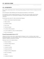
Illustration 1.1 Name Plate 1 and 2
1) Typecode
2) Ordering Number
3) Specifications
1-6: Product Name
7: Overload H: Heavy Duty
Q: Normal Duty
1)
8-10: Power Size 0.37-75 kW e.g.
K37: 0.37 kW
2)
1K1: 1.1 kW
11K: 11 kW etc.
11-12: Voltage Class 4: 380-480 V
13-15: IP Class E20: IP20
16-17: RFI H2: C3 Class
18: Braking Chopper X: No
B: Built-in
4)
19: LCP X: No
20: PCB Coating 3: 3C3
21: Mains Terminals D: Load Sharing
29-30: Embedded Fieldbus AX: No
A0: Profibus
3)
AL: Profinet
3)
Table 1.1 Type Code: Selection of Different Features and Options
See for options and accessories.
1) Only 11-75 kW for Normal Duty variants. Fieldbus unavailable for
Normal Duty.
2) For all power sizes see 2.4 Frame Sizes and Power Ratings
3) Not available yet.
4) 0.37-22 kW with built-in braking chopper. 30-75 kW external
braking chopper only.
130BC437.10
1 2 3 4 5 6 7 8 9 10 11 12 13 14 15 16 17 18 19 20 21 22 23 24 25 26 27 28 29 30 31 32
F C - 3 6 0 H T 4 E 2 0 H 2 X X C D X X S X X X X A X B X
Q B 0
L
A
A
Illustration 1.2 Typecode string
Quick Start
VLT
®
AutomationDrive FC 360 Quick Guide
MG06A102 - VLT
®
is a registered Danfoss trademark 3
1 1
1.2 Hand On/Auto On Mode
After installation (see 3 Installation) there are two simple
ways to start up the frequency converter, Hand On and
Auto On mode. The first time the frequency converter is
powered up it will be in auto on mode.
130BD062.10
D
Hand
On
Reset
Auto
On
OK
On
Warn
Alarm
Illustration 1.3 Location of Hand On, Off Reset and Auto On keys
on the NLCP
•
Press [Hand On] to provide a local start command
to the frequency converter. It is then possible to
increase and decrease the speed using the arrow
keys on the LCP.
•
Press [Off/Reset] to stop the frequency converter.
•
Press [Auto On] to control the frequency
converter either via control terminals or serial
communication.
CAUTION
Since the frequency converter is in auto on mode at first
power up, the frequency converter may start the motor
directly.
NOTE
Terminal 27 Digital input (5-12) has coast inverse as default
setting. Connect terminal 12 and 27 to test Hand On/Auto
On running.
For LCP operation, see 4 User Interface and Programming.
1.3
Application Selections
Use the selections for quick application set-up of the most
common applications by setting 0-16 Application Selections.
When necessary, the selections can be modified for
individual needs. All selections are for Auto On mode.
NOTE
When an application is selected, relevant parameters are
automatically set. Further setups to all parameters based
on specific requirements is still possible.
CAUTION
If any of the applications below are selected, relay 1 will
be set to [Running] and relay 2 will be set to [Alarm]
[1] Process Closed Loop
Application
Pumps, fans, compressors
130BC430.10
+24V 12
DI1 18
DI2 19
DI3 27
DI4 29
DI5 32
DI6 33
DI7 31
COM 20
+10V 50
AI1 53
-
+
AI2 54
COM 55
AO1 45
AO2 42
1
2
3
4
5
6
R1
R2
FC 360
Start
Coast inverse
Jog
4-20
mA
Description
For applications where a
value (e.g. pressure,
temperature) must be
kept at a desired level by
sensor feedback
Parameter settings
1-00 (Configuration Mode): [3] Process Close Loop
1-03 (Torque Characteristics): [1] Variable Torque
3-00 (Ref Range): [0] Min- Max
3-15 (Ref Source 1): [0] No Function
4-12 (Motor Low Limit): 30.0 Hz
4-14 (Motor High Limit): 50.0 Hz
5-10 (DI 18 Selection): [8] Start
5-12 (DI 27 Selection): [2] Coast Inverse
5-14 (DI 32 Selection): [14] Jog
5-40 (Relay 1 Selection): Running
5-40 (Relay 2 Selection): Alarm
6-22 (AI 54 Low): 4.0 mA
6-23 (AI 54 High): 20.0 mA
6-29 (AI 54 Mode): [0] Current Mode
6-70 (Term 45 Mode): [0] 0-20 mA
6-71 (AO45): [100] Output freq
6-90 (Term 42 Mode): [0] 0-20 mA
6-91 (AO42): [103] Motor current
7-20 (Process CL feedback source): [2] Analog input 54
Table 1.2
Quick Start
VLT
®
AutomationDrive FC 360 Quick Guide
4 MG06A102 - VLT
®
is a registered Danfoss trademark
11
[2] Local/Remote
Application
Local/Remote
130BC431.10
+24V 12
DI1 18
DI2 19
DI3 27
DI4 29
DI5 32
DI6 33
DI7 31
COM 20
+10V 50
AI1
53
-
+
AI2
54
COM 55
AO1
45
AO2 42
1
2
3
4
5
6
R1
R2
FC 360
Start
Coast inverse
Setup select
4-20
mA
Description
For applications
where the speed
reference can be
switched between
local potentiometer
and remote current
signal
Parameter settings Setup 1 Setup 2
0-10 (Active Set-
up)
[9] Multi Set-up [9] Multi Set-up
0-12 (Link Set-up) [20] Linked [20] Linked
1-00 (Configuration
Mode)
[0] Speed Open Loop [0] Speed Open Loop
3-00 (Ref Range) [0] Min- Max [0] Min- Max
3-15 (Ref Source 1) [1] AI 53 [2] AI 54
3-16 (Ref Source 2)
4-12 (Motor Low
Limit)
25.0 Hz 25.0 Hz
4-14 (Motor High
Limit)
50.0 Hz 50.0 Hz
5-10 (DI 18
Selection)
[8] Start [8] Start
5-12 (DI 27
Selection)
[2] Coast Inverse [2] Coast Inverse
5-14 (DI 32
Selection)
[23] Set-up select [23] Set-up select
5-40 (Relay 1
Selection)
Running Running
5-40 (Relay 2
Selection)
Alarm Alarm
6-10 (AI 53 Low) 0.07 V
6-11 (AI 53 High) 10 V
6-19 (AI 53 Mode) [1] Voltage Mode
6-22 (AI 54 Low) 4.0 mA
6-23 (AI 54 High) 20.0 mA
6-29 (AI 54 Mode) [0] Current Mode
6-70 (Term 45
Mode)
[0] 0-20 mA [0] 0-20 mA
6-71 (AO45) [100] Output freq [100] Output freq
6-90 (Term 42
Mode)
[0] 0-20 mA [0] 0-20 mA
6-91 (AO42) [103] Motor current [103] Motor current
Table 1.3
[3] Speed Open Loop
Application
Conveyors, extruders
130BC432.10
+24V 12
DI1 18
DI2 19
DI3 27
DI4 29
DI5 32
DI6 33
DI7 31
COM 20
+10V 50
AI1
53
AI2
54
COM 55
AO1
45
AO2 42
1
2
3
4
5
6
R1
R2
FC 360
Start
Coast inverse
Description
For running at a stable
speed by a voltage
reference signal.
Parameter settings
1-00 (Configuration Mode): [0] Speed Open Loop
3-00 (Ref Range): [0] Min- Max
3-15 (Ref Source 1): [1] AI 53
4-12 (Motor Low Limit): 25.0 Hz
4-14 (Motor High Limit): 50.0 Hz
5-10 (DI 18 Selection): [8] Start
5-12 (DI 27 Selection): [2] Coast Inverse
5-40 (Relay 1 Selection): Running
5-40 (Relay 2 Selection): Alarm
6-10 (AI 53 Low): 0.07 V
6-11 (AI 53 High): 10 V
6-19 (AI 53 Mode): [1] Voltage Mode
6-70 (Term 45 Mode): [0] 0-20 mA
6-71 (AO45): [100] Output freq
6-90 (Term 42 Mode): [0] 0-20 mA
6-91 (AO42): [103] Motor current
Table 1.4
Quick Start
VLT
®
AutomationDrive FC 360 Quick Guide
MG06A102 - VLT
®
is a registered Danfoss trademark 5
1 1
[4] Speed Close Loop
Application
Machine tools, texturizers
130BC433.10
+24V 12
DI1 18
DI2 19
DI3 27
DI4 29
DI5 32
DI6 33
DI7 31
COM 20
+10V 50
AI1
53
AI2
54
COM 55
AO1
45
AO2 42
1
2
3
4
5
6
R1
R2
FC 360
Start
Coast inverse
A
B
Description
For precise speed
applications with 24 V
encoder feedback
Parameter settings
1-00 (Configuration Mode): [1] Speed Close Loop
3-00 (Ref Range): [0] Min- Max
3-15 (Ref Source 1): [1] AI 53
3-16 (Ref Source 2): [11] Local Bus Ref
4-12 (Motor Low Limit): 20.0 Hz
4-14 (Motor High Limit): 50.0 Hz
5-10 (DI 18 Selection): [8] Start
5-12 (DI 27Selection): [2] Coast Inverse
5-14 (DI 32 Selection): [82] Encoder input B
5-15 (DI 23 Selection): [81] Encoder input A
5-40 (Relay 1 Selection): Running
5-40 (Relay 2 Selection): Alarm
6-10 (AI 53 Low): 0.07 V
6-11 (AI 53 High): 10 V
6-19 (AI 53 Mode): [1] Voltage Mode
7-00 (Speed PID Feedback Source): [1] 24 V encoder
Table 1.5
[5] Multi-speed
Application
Industrial washing
machines, conveyors
130BC434.10
+24V 12
DI1 18
DI2 19
DI3 27
DI4 29
DI5 32
DI6 33
DI7 31
COM 20
+10V 50
AI1
53
AI2
54
COM 55
AO1
45
AO2 42
1
2
3
4
5
6
R1
R2
FC 360
Start
Coast inverse
Pre set ref bit 0
Pre set ref bit 1
Pre set ref bit 2
Description
For applications with
8 different speeds by
digital input. By using
another digital input,
16 speeds are
possible.
Parameter settings
1-00 (Configuration Mode): [0] Speed Open Loop
3-00 (Ref Range): [0] Min- Max
3-15 (Ref Source 1): [0] No Function
4-14 (Motor High Limit): 50.0 Hz
5-10 (DI 18 Selection): [8] Start
5-12 (DI 27 Selection): [2] Coast Inverse
5-13 (DI 29 Selection): [16] Preset ref bit 0
5-14 (DI 32 Selection): [17] Preset ref bit 1
5-15 (DI 23 Selection): [18] Preset ref bit 2
6-70 (Term 45 Mode): [0] 0-20 mA
6-71 (AO45): [100] Output freq
6-90 (Term 42 Mode): [0] 0-20 mA
6-91 (AO42): [103] Motor current
Table 1.6
NOTE
For further examples refer to 5 Wiring Examples.
Quick Start
VLT
®
AutomationDrive FC 360 Quick Guide
6 MG06A102 - VLT
®
is a registered Danfoss trademark
11
1.4 Jumper Terminal 12 and 27
A jumper wire may be required between terminal 12 and
terminal 27 for the frequency converter to operate when
using factory default programming values.
•
Digital input terminal 27 is designed to receive an
24 V DC external interlock command. In many
applications, the user wires an external interlock
device to terminal 27
•
When no interlock device is used, wire a jumper
between control terminal 12 to terminal 27. This
provides in internal 24 V signal on terminal 27
•
No signal present prevents the unit from
operating
1.5 Automatic Motor Adaptation (AMA)
Automatic motor adaptation (AMA)
It is highly recommended to run AMA because it is a test
procedure that measures the electrical characteristics of
the motor to optimize compatibility between the
frequency converter and the motor under VVC
plus
mode.
•
The frequency converter builds a mathematical
model of the motor for regulating output motor
current thus enhancing motor performance.
•
Some motors may be unable to run the complete
version of the test. In that case, select Enable
reduced AMA
•
If warnings or alarms occur, see 6 Warnings and
Alarms
•
Run this procedure on a cold motor for best
results
NOTE
AMA does not cause the motor to run and it does not
harm the motor.
To run AMA using the numeric LCP (NLCP)
1. Enter the main menu.
2.
Go to parameter group 1-** Load and Motor.
3. Press [OK].
4. Set motor parameters using name plate data for
parameter group 1-2* Motor Data.
5.
Set motor cable length in 1-42 Motor Cable Length
6.
Go to 1-29 Automatic Motor Adaptation (AMA).
7. Press [OK].
8.
Select [1] Enable complete AMA.
9. Press [OK].
10. The test will run automatically and indicate when
it is complete.
NOTE
By default parameter setting, connect terminal 12 and 27
before running AMA.
Quick Start
VLT
®
AutomationDrive FC 360 Quick Guide
MG06A102 - VLT
®
is a registered Danfoss trademark 7
1 1
2 Introduction
2.1 Exploded Views
130BC439.10
17
16
15
14
13
12
11
10
9
8
7
6
5
4
3
2
1
03
02
01
05
04
Illustration 2.1 Exploded View J1-J5 (0.37-22 kW), IP20
1
NLCP (accessory) 10 2-Pole Relay 2 (0.37 kW-7.5 kW)
3-Pole Relay 2 (11 kW-22 kW)
2 Control cassette 11 Mains terminal
3 RFI switch (screw M3x12 only) 12 Cable strain relief (0.37-2.22 kW: accessory)
4 Removable fan assembly 13 RS-485 com pluggable terminal
5 Grounding clamp (accessory) 14 Fixed I/O terminals
6 Shielded cable grounding clamp and strain relief
(accessory)
15 Fixed I/O terminals
7 Motor terminal (U V W) and brake and load sharing
terminal
16 Terminal cover
8 PE ground 17 Option-B (MCB102/103 accessories)
9 3-Pole relay 1
Table 2.1
Introduction
VLT
®
AutomationDrive FC 360 Quick Guide
8 MG06A102 - VLT
®
is a registered Danfoss trademark
2
2
2.2 Product Overview
A frequency converter is an electronic motor controller
that converts AC mains input into a variable AC waveform
output. The frequency and voltage of the output are
regulated to control the motor speed or torque. The
frequency converter can vary the speed of the motor in
response to system feedback, such as changing
temperature or pressure for controlling fan, compressor, or
pump motors. The frequency converter can also regulate
the motor by responding to remote commands from
external controllers.
In addition, the frequency converter monitors the system
and motor status, issues warnings or alarms for fault
conditions, starts and stops the motor, optimizes energy
efficiency, and offers many more control, monitoring, and
efficiency functions. Operation and monitoring functions
are available as status indications to an outside control
system or serial communication network.
2.3 Additional Resources
Other resources are available to understand advanced
frequency converter functions and programming.
•
The Programming Guide provides greater detail
on working with parameters.
•
The Design Guide is intended to provide detailed
capabilities and functionality to design motor
control systems.
•
Optional equipment is available that may change
some of the procedures described. Be sure to see
the instructions supplied with those options for
specific requirements.
Contact the local Danfoss supplier or go to
/>+Documentation.htm for downloads.
2.4 Frame Sizes and Power Ratings
Frame size
380-480 V
J1 J2 J3 J4 J5 J6 J7
Power size [kW] 0.37-2.2 3.0-5.5 7.5 11-15 18.5-22 30-45 55-75
Dimensions
[mm]
A
a
D
C
B
b
130BC449.10
Height A 210 272.5 272.5 317.5 410 520 550
Width B 75 90 115 133 150 233 308
Depth C
(with option B)
168 (181) 168 (181) 168 (181) 245 (258) 245 (258) 242 332
Mounting holes
a 198 260 260 297.5 390
b 60 70 90 105 120
Mounting screw M4 M5 M5 M6 M6
Table 2.2 Frames Sizes, Power Ratings and Dimensions
Introduction
VLT
®
AutomationDrive FC 360 Quick Guide
MG06A102 - VLT
®
is a registered Danfoss trademark 9
2
2
3 Installation
3.1 Mechanical Installation
Select the best possible operation site by considering the
following:
•
Ambient operating temperature
•
Installation method
•
How to cool the unit
•
Position of the frequency converter
•
Cable routing
•
Power source supplying correct voltage and
necessary current
•
Motor current rating within the maximum current
from the frequency converter
•
Correct rating of external fuses and circuit
breakers
Cooling and Mounting:
•
Top and bottom clearance for air cooling must be
provided, see Table 3.1 for clearance requirements
•
Derating for temperatures starting from 45°C and
elevation 1000m above sea level must be
considered. See the equipment Design Guide for
detailed information.
Enclosure
J1-J5 J6/J7
Clearance above and below the
unit [mm]
100-200
Table 3.1 Minimum Airflow Clearance Requirements
•
Mount the unit vertically
•
IP20 units (but NOT IP21 units) allow side by side
installation
•
Improper mounting can result in over heating
and reduced performance
•
Use the slotted mounting holes on the unit for
wall mounting, when provided
•
See 8.4 Connection Tightening Torques for proper
tightening specifications.
Installation
VLT
®
AutomationDrive FC 360 Quick Guide
10 MG06A102 - VLT
®
is a registered Danfoss trademark
33
3.2 Electrical Installation
This section contains detailed instructions for wiring the frequency converter.
130BC438.11
3 Phase
power
input
Switch Mode
Power Supply
Motor
Analog Output
Interface
relay1
(PNP) = Source
(NPN) = Sink
ON=Terminated
OFF=Open
Brake
resistor
91 (L1)
92 (L2)
93 (L3)
PE
50 (+10 V OUT)
53 (A IN)
54 (A IN)
55 (COM A IN)
0/4-20 mA
12 (+24V OUT)
31 (D IN)
18 (D IN)
20 (COM D IN)
10Vdc
15mA 100mA
+ - + -
(U) 96
(V) 97
(W) 98
(PE) 99
(A OUT) 45
(A OUT) 42
(P RS-485) 68
(N RS-485) 69
(COM RS-485) 61
0V
5V
S801
0/4-20 mA
RS-485
RS-485
03
+10Vdc
0/4-20 mA
0-10V dc
240Vac, 2A
24Vdc
02
01
05
04
240Vac, 2A
24V (NPN)
0V (PNP)
0V (PNP)
24V (NPN)
19 (D IN)
24V (NPN)
0V (PNP)
27
24V
0V
(D IN/OUT)
0V (PNP)
24V (NPN)
(D IN/OUT)
0V
24V
29
24V (NPN)
0V (PNP)
0V (PNP)
24V (NPN)
33 (D IN)
32 (D IN)
95
P 5-00
21
ON
(+UDC) 82
(BR) 81
24V (NPN)
0V (PNP)
0-10V dc
(-UDC) 88
Illustration 3.1 Basic Wiring Schematic Drawing
A=Analog, D=Digital
1) Built-in braking chopper available from 0.37 - 22 kW
2) Relay 2 is 2 pole for J1-J3 and 3 pole for J4-J7. Relay 2 of J4-J7 with terminal 4,5,6, same NO/NC logic as Relay 1.
Installation
VLT
®
AutomationDrive FC 360 Quick Guide
MG06A102 - VLT
®
is a registered Danfoss trademark 11
3 3
130BD109.10
1
2
3
4
5
6
78
9
10
O
Reset
Auto
On
Hand
On
OK
Back
Menu
Status Quick
Menu
Main
Menu
PE
U
V
W
L1
L2
L3
PE
Illustration 3.2 Typical Electrical Connection
1
PLC 6 Min. 200 mm (7.9 in) between control cables, motor and mains
2 Frequency converter 7 Motor, 3-phase and PE
3 Output contactor (Generally not recommended) 8 Mains, 3-phase and reinforced PE
4 Earth (grounding) rail (PE) 9 Control wiring
5 Cable insulation (stripped) 10
Equalising min. 16 mm
2
(0.025 in)
Table 3.2
Installation
VLT
®
AutomationDrive FC 360 Quick Guide
12 MG06A102 - VLT
®
is a registered Danfoss trademark
33
3.2.1 General Requirements
WARNING
EQUIPMENT HAZARD!
Rotating shafts and electrical equipment can be hazardous.
Extreme care should be taken to protect against electrical
hazards when applying power to the unit. All electrical
work must conform to national and local electrical codes
and installation, start up, and maintenance should only be
performed by trained and qualified personnel. Failure to
follow these guidelines could result in death or serious
injury.
CAUTION
WIRING ISOLATION!
Run input power, motor wiring and control wiring in three
separate metallic conduits or use separated shielded cable
for high frequency noise isolation. Failure to isolate power,
motor and control wiring could result in less than
optimum frequency converter and associated equipment
performance.
Run motor cables from multiple frequency converters
separately. Induced voltage from output motor cables run
together can charge equipment capacitors even with the
equipment turned off and locked out.
•
An electronically activated function within the
frequency converter provides overload protection
for the motor. The overload provides Class 20
motor protection. See 6 Warnings and Alarms for
details on the trip function.
Wire Type and Ratings
•
All wiring must comply with local and national
regulations regarding cross-section and ambient
temperature requirements.
•
Danfoss recommends that all power connections
be made with a minimum 75° C rated copper
wire.
•
See 8 Specifications for recommended wire sizes.
3.2.2
Earth (Grounding) Requirements
WARNING
GROUNDING HAZARD!
For operator safety, it is important to ground the
frequency converter properly by a certified electrical
installer in accordance with national and local electrical
codes as well as instructions contained within this
document. Ground currents are higher than 3,5 mA. Failure
to ground the frequency converter properly could result in
death or serious injury.
•
Proper protective grounding for equipment with
ground currents higher than 3,5 mA must be
established, see Leakage Current (>3,5 mA)
•
A dedicated ground wire is required for input
power, motor power and control wiring
•
Use the clamps provided with the equipment for
proper ground connections
•
Do not ground one frequency converter to
another in a “daisy chain” fashion (see
Illustration 3.3)
•
Keep the ground wire connections as short as
possible
•
Using high-strand wire to reduce electrical noise
is recommended
•
Follow motor manufacturer wiring requirements
130BC500.10
FC 1
FC 1
FC 2
FC 2
FC 3
FC 3
PE
PE
Illustration 3.3 Grounding Principle
3.2.2.1
Leakage Current (>3,5 mA)
Follow national and local codes regarding protective
earthing of equipment with a leakage current > 3,5 mA.
The earth leakage current depends on various system
configurations including RFI filtering, screened motor
cables, and frequency converter power.
EN/IEC61800-5-1 (Power Drive System Product Standard)
requires special care if the leakage current exceeds 3,5 mA.
Earth grounding must be reinforced in one of the
following ways:
Installation
VLT
®
AutomationDrive FC 360 Quick Guide
MG06A102 - VLT
®
is a registered Danfoss trademark 13
3 3
•
Earth ground wire of at least 10 mm
2
•
Two separate earth ground wires both complying
with the dimensioning rules
See EN 60364-5-54 § 543.7 for further information.
Using RCDs
Where residual current devices (RCDs), also known as earth
leakage circuit breakers (ELCBs), are used, comply with the
following:
•
Use RCDs of type B only which are capable of
detecting AC and DC currents
•
Use RCDs with an inrush delay to prevent faults
due to transient earth currents
•
Dimension RCDs according to the system configu-
ration and environmental considerations
3.2.3
Mains, Motor and Earth Connections
WARNING
INDUCED VOLTAGE!
Run output motor cables from multiple frequency
converters separately. Induced voltage from output motor
cables run together can charge equipment capacitors even
with the equipment turned off and locked out. Failure to
run output motor cables separately could result in death
or serious injury.
Earthing (grounding) clamps are provided for motor wiring
(see Illustration 3.4).
•
Do not install power factor correction capacitors
between the frequency converter and the motor
•
Do not wire a starting or pole-changing device
between the frequency converter and the motor
•
Follow motor manufacturer wiring requirements
•
All frequency converters may be used with an
isolated input source as well as with ground
reference power lines. When supplied from an
isolated mains source (IT mains or floating delta)
or TT/TN-S mains with a grounded leg (grounded
delta), set 14-50 RFI Filter to OFF (size J6-J7) or
remove the RFI screw (J1-J5). When off, the
internal RFI filter capacitors between the chassis
and the intermediate circuit are isolated to avoid
damage to the intermediate circuit and to reduce
earth capacity currents in accordance with IEC
61800-3.
•
Do not install switch between the frequency
converter and the motor in IT mains.
130BC501.10
01
02 03
04
05
Illustration 3.4 Mains, Motor and Earth Connections
Illustration 3.4 represents mains input, motor, and earth
grounding for basic frequency converters. Actual configu-
rations vary with unit types and optional equipment.
3.2.4
Control Wiring
3.2.4.1 Access
•
Remove access cover plate with a screw driver.
See Illustration 3.5.
130BC504.10
Illustration 3.5 Control Wiring Access for J1-J7 Enclosures
Installation
VLT
®
AutomationDrive FC 360 Quick Guide
14 MG06A102 - VLT
®
is a registered Danfoss trademark
33
3.2.4.2 Control Terminal Types
Illustration 3.6 shows the frequency converter control
terminals. Terminal functions and default settings are
summarized in Table 3.4.
130BC505.11
42 45
12
18
19
27
29
31
32
33
20
50
53
54
55
Illustration 3.6 Control Terminal Locations
See 8.2 General Technical Data for terminal ratings details.
Terminal description
Termi
nal
Parame
ter
Default
setting Description
Digital I/O, Pulse I/O, Encoder
12 - +24 V DC 24 V DC supply voltage.
Maximum output current is
100mA for all 24 V loads.
18 5-10 [8] Start
Digital inputs.
19 5-11 [10] Reversing
31 5-16 [0] No operation Digital input, pulse input.
32 5-14 [0] No operation
Digital input, 24 V encoder.
33 5-15 [0] No operation
27 5-12
5-30
DI [2] Coast
inverse
DO [0] No
operation
Selectable for either digital
input, digital output or
pulse output. Default
setting is digital input.
29 5-13
5-31
DI [14] Jog
DO [0] No
operation
20 - Common for digital inputs
and 0V potential for 24V
supply.
Analog inputs/outputs
42 6-91 [0] No operation Programmable analog
output. The analog signal
is 0-20mA or 4-20 mA at a
maximum of 500Ω. Can
also be configured as
digital outputs
45 6-71 [0] No operation
Terminal description
Termi
nal
Parame
ter
Default
setting Description
50 - +10 V DC 10 V DC analog supply
voltage. 15mA maximum
commonly used for
potentiometer or
thermistor.
53 6-1* Reference
Analog input. Selectable
for voltage or current.
54 6-2* Feedback
55 - Common for analog input
Table 3.3
Terminal description
Termi
nal
Parame
ter
Default
setting Description
Serial communication
61 -
Integrated RC-Filter for
cable screen. ONLY for
connecting the screen
when experiencing EMC
problems.
68 (+) 8-3* RS-485 Interface. A control
card switch is provided for
termination resistance.
69 (-) 8-3*
Relays
01, 02,
03 5-40 [0] [0] No operation
Form C relay output. These
relays are in various
locations depending upon
the frequency converter
configuration and size.
Usable for AC or DC
voltage and resistive or
inductive loads.
RO2 in J1-J3 enclosure is 2-
pole, only 04,05 terminal
available
04, 05,
06
5-40 [1] [0] No operation
Table 3.4 Terminal Description
Installation
VLT
®
AutomationDrive FC 360 Quick Guide
MG06A102 - VLT
®
is a registered Danfoss trademark 15
3 3
3.2.4.3 Control Terminal Functions
Frequency converter functions are commanded by
receiving control input signals.
•
Each terminal must be programmed for the
function it will be supporting in the parameters
associated with that terminal. SeeTable 3.4 for
terminals and associated parameters.
•
It is important to confirm that the control
terminal is programmed for the correct function.
See 4 User Interface and Programming for details
on accessing parameters and for details on
programming.
•
The default terminal programming is intended to
initiate frequency converter functioning in a
typical operational mode.
3.2.4.4
Using Screened Control Cables
Correct screening
The preferred method in most cases is to secure control
and serial communication cables with screening clamps
provided at both ends to ensure best possible high
frequency cable contact.
If the earth potential between the frequency converter and
the PLC is different, electric noise may occur that will
disturb the entire system. Solve this problem by fitting an
equalizing cable next to the control cable. Minimum cable
cross section: 16 mm
2
.
1
2
PE
FC
PE
PLC
130BB922.11
PE PE
Illustration 3.7
1
Min. 16 mm
2
2 Equalizing cable
Table 3.5
50/60Hz ground loops
With very long control cables, ground loops may occur. To
eliminate ground loops, connect one end of the screen-to-
ground with a 100nF capacitor (keeping leads short).
100nF
FC
PE
PE
PLC
130BB609.11
Illustration 3.8
Avoid EMC noise on serial communication
This terminal is connected to earth via an internal RC link.
Use twisted-pair cables to reduce interference between
conductors. The recommended method is shown below:
PE
FC
PE
FC
130BB923.11
PE PE
69
68
61
69
68
61
1
2
Illustration 3.9
1
Min. 16 mm
2
2 Equalizing cable
Table 3.6
Alternatively, the connection to terminal 61 can be
omitted:
PE
FC
PE
FC
130BB924.11
PE PE
69
69
68
68
1
2
Illustration 3.10
1
Min. 16 mm
2
2 Equalizing cable
Table 3.7
Installation
VLT
®
AutomationDrive FC 360 Quick Guide
16 MG06A102 - VLT
®
is a registered Danfoss trademark
33
3.3 Serial Communication
Connect RS-485 serial communication wiring to terminals
(+)68 and (-)69.
•
Screened serial communication cable is
recommended
•
See 3.2.2 Earth (Grounding) Requirements for
proper grounding
61
68
69
+
130BB489.10
RS-485
Illustration 3.11 Serial Communication Wiring Diagram
For basic serial communication set-up, select the following
1.
Protocol type in 8-30 Protocol.
2.
Frequency converter address in 8-31 Address.
3.
Baud rate in 8-32 Baud Rate.
•
Two communication protocols are internal to the
frequency converter. Follow motor manufacturer
wiring requirements.
Danfoss FC
Modbus RTU
•
Functions can be programmed remotely using
the protocol software and RS-485 connection or
in parameter group 8-** Communications and
Options
•
Selecting a specific communication protocol
changes various default parameter settings to
match that protocol’s specifications along with
making additional protocol-specific parameters
available
Installation
VLT
®
AutomationDrive FC 360 Quick Guide
MG06A102 - VLT
®
is a registered Danfoss trademark 17
3 3
4 User Interface and Programming
4.1 Programming
4.1.1 Programming with the Numerical
Local Control Panel (NLCP)
The FC 360 supports graphic and numerical local control
panels as well as blind covers. This chapter covers
programming with the NLCP. For programming with the
GLCP, see the VLT
®
Programming Guide, MG06C.
NOTE
The frequency converter can also be programmed from a
PC via RS-485 com-port by installing the MCT-10 Setup
software. This software can either be ordered using code
number 130B1000 or downloaded from the Danfoss Web
site: www.danfoss.com/BusinessAreas/DrivesSolutions/
softwaredownload
4.1.2 NLCP
The NLCP is divided into four functional sections.
A. Numeric display
B. Menu key
C. Navigation keys and indicator lights (LEDs)
D. Operation keys and indicator lights (LEDs)
130BC506.10
Setup 1
A
B
C
D
5
12
13 14 15
10
11
10
9
6
7
8
4
1
2
3
Menu
Status
Quick
Menu
Main
Menu
Hand
On
O
Reset
Auto
On
Back
OK
On
Warn
Alarm
Illustration 4.1
A. Numeric Display
The LCD-display is back-lit with 1 numeric line. All data is
displayed on the LCP.
1 Set-up number shows the active set-up and the edit set-
up. If the same set-up acts as both active and edit set-up,
only that set-up number is shown (factory setting). When
active and edit set-up differ, both numbers are shown in
the display (Setup 12). The number flashing, indicates the
edit set-up.
2 Parameter number.
3 Parameter value.
4 Motor direction is shown to the bottom left of the display
– indicated by a small arrow pointing either clockwise or
counterclockwise.
5 The triangle indicates if the LCP is in status, quick menu or
main menu.
Table 4.1
130BD135.10
Setup 12
INDEX
AHP
VkW
srpm
Hz%
n2n1
n3
p5 p4
p3 p2 p1
Illustration 4.2 Display Information
B. Menu Key
Use the menu key to select between status, quick menu or
main menu.
C. Navigation keys and indicator lights (LEDs)
6
Green LED/On: Control section is working.
7 Yellow LED/Warn.: Indicates a warning.
8 Flashing Red LED/Alarm: Indicates an alarm.
9 [Back]: For moving to the previous step or layer in the
navigation structure
10
Arrows [
▲
] [
▼
]: For maneuvering between parameter groups,
parameters and within parameters or increasing/decreasing
parameter values. Can also be used for setting local
reference.
11 [OK]: For selecting a parameter and for accepting changes to
parameter settings
12
[►]: For moving from left to right within the parameter value
in order to change each digit individually. See description in
4.1.3 The Right-Key Function.
Table 4.2
User Interface and Programm
VLT
®
AutomationDrive FC 360 Quick Guide
18 MG06A102 - VLT
®
is a registered Danfoss trademark
44
D. Operation keys and indicator lights (LEDs)
13 [Hand On]: Starts the motor and enables control of the
frequency converter via the LCP.
NOTE
Terminal 27 Digital Input (5-12 Terminal 27 Digital
Input) has coast inverse as default setting. This
means that [Hand On] will not start the motor if
there is no 24 V to terminal 27.
14 [Off/Reset]: stops the motor (off). If in alarm mode the
alarm will be reset.
15 [Auto On]: frequency converter is controlled either via
control terminals or serial communication.
Table 4.3
4.1.3
The Right-Key Function
WARNING
The [Off/Reset] key is not a safety switch. It does not
disconnect the frequency converter from mains.
[►] makes it possible to edit any of the four digits on the
display individually. When pressing [►] once the cursor
moves to the first digit and the digit starts flashing as
shown in Illustration 4.3. The value can now be changed
using the [
▲
] [
▼
] navigation keys. Pressing [►] will not
change the value of the digits or move the decimal point.
130BC440.10
Setup 1
Setup 1
Setup 1
Setup 1
Setup 1
Illustration 4.3 Right Key Function
The right key can also be used for moving between
parameter groups: when in main menu, press the right key
to move to the first parameter in the next parameter
group (e.g. move from 0-03 [0] to 1-00 [0]).
User Interface and Programm
VLT
®
AutomationDrive FC 360 Quick Guide
MG06A102 - VLT
®
is a registered Danfoss trademark 19
4 4
4.2 Quick Menu
The Quick Menu gives easy access to the most frequently
used parameters.
1. To enter the Quick Menu, press [Menu] key until
indicator in display is placed above Quick Menu.
2.
Use [
▲
] [
▼
] to select either QM1 or QM2, then
press [OK].
3.
Use [
▲
] [
▼
] to browse through the parameters in
the Quick Menu.
4. Press [OK] to select a parameter.
5.
Use [
▲
] [
▼
] to change the value of a parameter
setting.
6. Press [OK] to accept the change.
7. To exit, press either [Back] twice (or three times if
in QM” and QM3) to enter Status, or press [Menu]
once to enter Main Menu.
User Interface and Programm
VLT
®
AutomationDrive FC 360 Quick Guide
20 MG06A102 - VLT
®
is a registered Danfoss trademark
44
130BC445.11
1-22 XXXX V
Motor
nominal
speed
QM 1
0-01
[0]
1-10 [0]
1-24 XXXX A
Language
Motor Type
PM Motor
Asynchronous Motor
1-20 XXXX kW
Motor power
Motor voltage
Motor Cont.
Rated Torque
1-26 XXXX 1-23 XXXX
Hz
Stator
Resistance
Motor frequency
1-25 XXXX rpm
(Rs)
1-30 XXXX
1-39 XXXX
1-40 XXXX
30-80 XXXX
1-25 XXXX rpm
1-24 XXXX
A
Motor Current
3-02 XXXX Hz
3-03 XXXX Hz
3-41 XXXX S
3-42 XXXX S
5-12
[2]
1-29 [1]
Minimum Reference
Maximum Reference
Ramp 1 Ramp up Time
Ramp 1 Ramp Down Time
Terminal 27 Digital input
AMA
Motor Poles
Back EMF at
1000 RPM
d-axis
Inductance (Ld)
Basic Motor Setup
Adv. Motor Setup Encoder Setup
QM 2
BMS
AMS
ES
5-70 XXXX
5-71
[0]
1-30 XXXX
1-39 XXXX
1-90
[0]
2-10 [0]
4-16 XXXX %
4-17 XXXX %
4-18 XXXX %
1-00 [0]
1-01 [1]
1-10 [0]
1-24 XXXX A 1-20 XXXX kW
1-22 XXXX V
Motor
nominal
speed
PM Motor Asynchronous Motor
Motor power
Motor voltage
Motor Cont.
Rated Torque
1-26 XXXX 1-23 XXXX Hz
Stator
Resistance
Motor frequency
1-25 XXXX rpm
(Rs)
1-30 XXXX
1-40 XXXX
30-80 XXXX
1-25 XXXX rpm
1-24 XXXX
A
Motor Current
Motor Poles
Back EMF at
1000 RPM
d-axis
Inductance (Ld)
1-39 XXXX
4-19 XXXX
Hz
4-14 XXXX Hz
Stator
Resistance
(Rs)
Motor Poles
Motor
Thermal Protection
Brake Function
Torque Limit Motor Mode
Torque Limit Generator Mode
Current Limit
Term 32/33 Pulses
per Revolution
Term 32/33
Encoder Direction
QM 3
QM 4 QM 5
L10C
SFS
Last 10 Changes Since Factory Setting
Changes Made
Alarm Log TBD
Motor Current
Motor
nominal
speed
Motor
nominal
speed
Motor
Current
Mode
Motor Control
Principle
Motor Type
Motor Speed High Limit [Hz]
Max Output Frequency
Illustration 4.4 Quick Menu Structure
User Interface and Programm
VLT
®
AutomationDrive FC 360 Quick Guide
MG06A102 - VLT
®
is a registered Danfoss trademark 21
4 4