control of deflection in concrete structuresstate-of-the-art report on fiber reinforced plastic (frp) reinforceme
Bạn đang xem bản rút gọn của tài liệu. Xem và tải ngay bản đầy đủ của tài liệu tại đây (14.5 MB, 68 trang )
440R-1
The use of FRP as reinforcement for concrete structures has been growing
rapidly in recent years. This state-of-the-art report summarizes the current
state of knowledge on these materials. In addition to the material proper-
ties of the constituents, i.e. resins and fibers, design philosophies for rein-
forced and prestressed elements are discussed. When the available data
warrants, flexure, shear and bond behavior, and serviceability of the mem-
bers has been examined. Strengthening of existing structures with FRPs
and field applications of these materials are also presented.
Keywords : analysis; composite materials; concrete; concrete construction;
design; external reinforcement; fibers; fiber reinforced plastic (FRP);
mechanical properties; polymer resin; prestressed concrete; reinforcement;
reinforced concrete; research; structural element; test methods; testing.
CONTENTS
Chapter 1—Introduction and history, p. 440R-2
1.1—Introduction
1.2—History of the U.S. pultrusion industry
1.3—Evolution of FRP reinforcement in the U.S.A.
1.4—FRP materials
Chapter 2—FRP composites: An overview of constituent
materials, p. 440R-6
2.1—Introduction
2.2—The importance of the polymer matrix
2.3—Introduction to matrix polymers
2.4—Polyester resins
2.5—Epoxy resins
ACI 440R-96
State-of-the-Art Report on Fiber Reinforced Plastic (FRP)
Reinforcement for Concrete Structures
Reported byACICommittee 440
A. Nanni
*
Chairman
H. Saadatmanesh
*
Secretary
M. R. Ehsani*
Subcommittee chairman
for the State-of-the- Art
Report
S. Ahmad C. W. Dolan* H. Marsh* V. Ramakrishnan
P. Albrecht H. Edwards M. Mashima S. H. Rizkalla*
A. H. Al-Tayyib S. Faza* C. R. McClaksey N. Santoh
l
-
P. N. Balaguru D. M. Gale* H. Mutsuyoshi M. Schupack
C. A. Ballinger H. R. Ganz A. E. Naaman Y. Sonobe
L. C. Bank A. Gerritse T. Okamoto J. D. Speakman
N. Banthia C. H. Goodspeed* E. O’Neil M. Sugita
H. Budelmann M. S. Guglielmo S. L. Phoix L. Taerwe
C. J. Burgoyne J. Hickman M. Porter T. Uomoto
P. Catsman S. L. Iyer* A. H. Rahman M. Wecharatana
T. E. Cousins* M. E. MacNeil
* Members of the subcommittee on the State-of-the-Art Report.
†
Deceased.
In addition to those listed above, D. Barno contributed to the preparation of the report.
The American Concrete Institute does not endorse products or
manufacturers mentioned in this report. Trade names and man-
ufacturers’ names are used only because they are considered es-
sential to the objective of this report.
ACI Committee Reports, Guides, Standard Practices, Design
Handbooks, and Commentaries are intended for guidance in
planning, designing, executing, and inspecting construction.
This document is intended for the use of individuals who are
competent to evaluate the significance and limitations of its
content and recommendations and who will accept responsibil-
ity for the application of the material it contains. The American
Concrete Institute disclaims any and all responsibility for the
application of the stated principles. The Institute shall not be li-
able for any loss or damage arising therefrom.
Reference to this document shall not made in contract docu-
ments. If items found in this document are desired by the Archi-
tect/Engineer to be a part of the contract documents, they shall
be restated in mandatory language for incorporation by the Ar-
chitect/Engineer.
ACI 440R-96 became effective January 1, 1996.
Copyright © 1996, American Concrete Institute.
All rights reserved including rights of reproduction and use in any form or by any
means, including the making of copies by any photo process, or by electronic or
mechanical device, printed, written, or oral, or recording for sound or visual reproduc-
tion or for use in any knowledge or retrieval system or device, unless permission in
writing is obtained from the copyright proprietors.
(Reapproved 2002)
440R-2 MANUAL OF CONCRETE PRACTICE
2.6—Processing considerations associated with polymer
matrix resins
2.7—Structural considerations in processing polymer ma-
trix resins
2.8—Reinforcing fibers for structural composites
2.9—Glass fibers
2.10—Carbon fibers
2.11—Aramid fibers
2.12—Other organic fibers
2.13—Hybrid reinforcements
2.14—Processes for structural moldings
2.15—Summary
Chapter 3—Mechanical properties and test methods, p.
440R-20
3.1—Physical and mechanical properties
3.2—Factors affecting mechanical properties
3.3—Gripping mechanisms
3.4—Theoretical modeling of GFRP bars
3.5—Test methods
Chapter 4—Design guidelines, p. 440R-24
4.1—Fundamental design philosophy
4.2—Ductility
4.3—Constitutive behavior and material properties
4.4—Design of bonded FRP reinforced members
4.5—Unbonded reinforcement
4.6—Bonded plate reinforcement
4.7—Shear design
Chapter 5—Behavior of structural elements, p. 440R-27
5.1—Strength of beams and slabs reinforced with FRP
5.2—Serviceability
5.3—RP tie connectors for sandwich walls
Chapter 6—Prestressed concrete elements, p. 440R-35
6.1—Strength of FRP prestressed concrete beams
6.2—Strength of FRP post-tensioned concrete beams
Chapter 7—External reinforcement, p. 440R-39
7.1—Strength of FRP post-reinforced beams
7.2—Wrapping
7.3—External unbonded prestressing
Chapter 8—Field applications, p. 440R-42
8.1—Reinforced concrete structures
8.2—Pre- and post-tensioned concrete structures
8.3—Strengthening of concrete structures
Chapter 9—Research needs, p. 440R-52
9.1—Materials behavior
9.2—Behavior of concrete members
9.3—Design guidelines
Chapter 10—References, p. 440R-57
Appendix A—Terminology, p. 440R-66
CHAPTER 1—INTRODUCTION AND HISTORY
1.1—Introduction
Fiber Reinforced Plastic (FRP) products were first used to
reinforce concrete structures in the mid 1950s (Rubinsky and
Rubinsky 1954; Wines et al. 1966). Today, these FRP prod-
ucts take the form of bars, cables, 2-D and 3-D grids, sheet
materials, plates, etc. FRP products may achieve the same or
better reinforcement objective of commonly used metallic
products such as steel reinforcing bars, prestressing tendons,
and bonded plates. Application and product development ef-
forts in FRP composites are widespread to address the many
opportunities for reinforcing concrete members (Nichols
1988). Some of these efforts are:
• High volume production techniques to reduce manufac-
turing costs
• Modified construction techniques to better utilize the
strength properties of FRP and reduce construction
costs
• Optimization of the combination of fiber and resin ma-
trix to ensure optimum compatibility with portland ce-
ment
• Other initiatives which are detailed in the subsequent
chapters of this report
The common link among all FRP products described in
this report is the use of continuous fibers (glass, aramid, car-
bon, etc.) embedded in a resin matrix, the glue that allows the
fibers to work together as a single element. Resins used are
thermoset (polyester, vinyl ester, etc.) or thermoplastic (ny-
lon, polyethylene terephthalate, etc.). FRP composites are
differentiated from short fibers used widely today to rein-
force nonstructural cementitious products known as fiber re-
inforced concrete (FRC). The production methods of
bringing continuous fibers together with the resin matrix al-
lows the FRP material to be tailored such that optimized re-
inforcement of the concrete structure is achieved. The
pultrusion process is one such manufacturing method widely
practiced today. It is used to produce consumer and construc-
tion products such as fishing rods, bike flags, shovel handles,
structural shapes, etc. The pultrusion process brings together
continuous forms of reinforcements and combines them with
a resin to produce high-fiber volume, directionally oriented
FRP products. This, as well as other manufacturing process-
es used to produce FRP reinforcement for concrete struc-
tures, is explained in more detail later in the report.
The concrete industry's primary interest in FRP reinforce-
ment is in the fact that it does not ordinarily cause durability
problems such as those associated with steel reinforcement
corrosion. Depending on the constituents of an FRP compos-
ite, other deterioration phenomena can occur as explained in
the report. Concrete members can benefit from the following
features of FRP reinforcement: light weight, high specific
strength and modulus, durability, corrosion resistance,
chemical and environmental resistance, electromagnetic per-
meability, and impact resistance.
Numerous FRP products have been and are being devel-
oped worldwide. Japan and Europe are more advanced than
the U.S. in this technology and claim a larger number of
FRP REINFORCEMENT
440R-3
completed field applications because their systematic re-
search and development efforts started earlier and because
their construction industry has taken a leading role in devel-
opment efforts.
1.2—History of the U.S. pultrusion industry
Pultrusion of composites took off immediately after the
Second World War. In the U.S., a booming post-war econo-
my created a demand for numerous improved recreational
products, the first of which was a solid glass FRP fishing
pole. Then came golf course flag staffs and ski poles. As the
pultrusion industry gained momentum, other markets devel-
oped. The 1960s saw use in the electric utility market due to
superior compressive and tensile strengths, along with excel-
lent electrical insulating properties. The following decade
saw advances in structural shapes and concrete reinforce-
ments, in addition to continuing growth in recreational, elec-
tric utility, and such residential products as ladder channels
and rails. Today, the automotive, electronic, medical, and
aerospace industries all specify highly advanced pultrusions
incorporating the latest in reinforcement fibers encapsulated
in the most recent resin formulations.
1.3—Evolution of FRP reinforcement
In the 1960s corrosion problems began to surface with
steel reinforced concrete in highway bridges and structures.
Road salts in colder climates or marine salt in coastal areas
accelerated corrosion of the reinforcing steel. Corrosion
products would expand and cause the concrete to fracture.
The first solution was a galvanized coating applied to the re-
inforcing bars. This solution soon lost favor for a variety of
reasons, but mainly because of an electrolytic reaction be-
tween the steel and the zinc-based coating leading to a loss
of corrosion protection.
In the late 1960’s several companies developed an electro-
static-spray fusion-bonded (powdered resin) coating for
steel oil and gas pipelines. In the early 1970s the Federal
Highway Administration funded research to evaluate over
50 types of coatings for steel reinforcing bars. This led to the
current use of epoxy-coated steel reinforcing bars.
Research on use of resins in concrete started in the late
1960s with a program at the Bureau of Reclamation on poly-
mer-impregnated concrete. Unfortunately, steel reinforce-
ment could not be used with polymer concrete because of
incompatible thermal properties. This fact led Marshall-
Vega (later renamed Vega Technologies and currently re-
formed under the name Marshall-Vega Corporation) to man-
ufacture a glass FRP reinforcing bar. The experiment
worked and the resultant composite reinforcing bar became
a reinforcement-of-choice for polymer concrete.
In spite of earlier research on the use of FRP reinforcement
in concrete, commercial application of this product in con-
ventional concrete was not recognized until the late 1970s.
At that time, research started in earnest to determine if com-
posites were a significant improvement over epoxy coated
steel. During the early 1980s, another pultrusion company,
International Grating, Inc., recognized the product potential
and entered the FRP reinforcing bar industry.
In the 1980s there was increased use of FRP reinforcing
bars in applications with special performance requirements
or where reinforcing bars were subjected to severe chemical
attack. Perhaps the largest market, then and even today, is for
reinforced concrete to support or surround magnetic reso-
nance imaging (MRI) medical equipment. For these struc-
tures, the conventional steel reinforcement cannot be used.
Glass FRP reinforcing bars have continued to be selected by
structural designers over nonmagnetic (nitronic) stainless
steel. Composite reinforcing bars have more recently been
used, on a selective basis, for construction of some seawalls,
industrial roof decks, base pads for electrical and reactor
equipment, and concrete floor slabs in aggressive chemical
environments.
In 1986, the world’s first highway bridge using composite
reinforcement was built in Germany. Since then, there have
been bridges constructed throughout Europe and, more re-
cently, in North America and Japan. The U.S. and Canadian
governments are currently investing significant sums fo-
cused on product evaluation and further development. It ap-
pears that the largest markets will be in the transportation
industry. At the end of 1993, there were nine companies ac-
tively marketing commercial FRP reinforcing bars.
1.4—FRP composites
The concrete reinforcing products described in this state-
of-the-art report are FRP composites. This class of materials
is defined as a polymer matrix, whether thermosetting (e.g.,
polyester, vinyl ester, epoxy, phenolic) or thermoplastic
(e.g., nylon, PET) which is reinforced by fibers (e.g., aramid,
carbon, glass). Specific definitions used within the report
also include glass-fiber reinforced plastic (GFRP), carbon fi-
ber reinforced plastic (CFRP) and related abbreviations. For
a more complete listing of definitions not included in ACI
116R—Cement and Concrete Terminology, see the glossary
of terms in Appendix A. A description of FRP composites
and their constitutive materials is given in Chapter 2.
The following sections contain a brief description of some
of the most successful technologies and products presently
available in North America, Japan, and Europe.
1.4.1 North America—Nine companies have marketed or
are currently marketing FRP reinforcing bars for concrete in
North America, including Autocon Composites, Corrosion
Proof Products, Creative Pultrusions, International Grating,
Marshall Industries Composites, Marshall-Vega Corpora-
tion, Polystructures, Polygon, and Pultrall. Current produc-
ers offer a pultruded FRP bar made of E-glass (other fiber
types also available) with choice of thermoset resin (e.g.,
isophthalic polyester, vinyl ester). There are a number of
other FRP products manufactured for use in concrete con-
struction, for example bars and gripping devices for concrete
formwork, products for tilt-up construction, and reinforce-
ment support.
In order to enhance the bond between FRP reinforcing bar
and concrete, several companies have explored the use of
surface deformations. For example, Marshall-Vega Corpora-
tion produced an E-glass FRP reinforcing bar with deformed
surface (Pleimann 1991) obtained by wrapping the bar with
440R-4 MANUAL OF CONCRETE PRACTICE
an additional resin-impregnated strand in a 45-deg helical
pattern prior to entering the heated die that polymerizes the
resin. The matrix used was a thermosetting vinyl ester resin.
Similar reinforcing bars are currently being produced by In-
ternational Grating under the name KODIAK™ and by
Polystructures under the name PSI Fiberbar™.
Polygon Company has produced pultruded bars made of
carbon and S-glass fibers and using epoxy and vinyl ester
resins for the matrix (Iyer et al. 1991). The bars, 3 mm (0.12
in.) in diameter, are twisted to make a 7-rod strand, 9.5 mm
(0.37 in.) in diameter. Prototype applications limited to piles
(Florida) and a bridge deck (South Dakota) have been con-
structed using these FRP strands (see Chapter 8).
International Grating manufactures FRP bars made of E-
glass and vinyl ester resin. These reinforcing bars, intended
for nonprestressed reinforcement, have diameters varying
between 9 and 25 mm (0.35 and 1.0 in.), and can be coated
with sand to improve mechanical bond to concrete. The ulti-
mate strength of the bars significantly decreases with in-
creasing diameter. A number of publications dealing with
the performance of both the bars and the concrete members
reinforced with them is available (Faza 1991; Faza and Gan-
gaRao 1991a and 1991b).
In Canada, Pultrall Inc. manufactures an FRP reinforcing
bar under the name of Isorod™. This reinforcing bar is made
of continuous longitudinal E-glass fibers bound together
with a polyester resin using the pultrusion process. The re-
sulting bar has a smooth surface that can be deformed with a
helical winding of the same kind of fibers. A thermosetting
polyester resin is applied, as well as a coating of sand parti-
cles of a specific grain-size distribution. The pitch of the de-
formations can be adjusted using different winding speeds.
A preliminary study carried out during the development of
this product (Chaallal et al. 1991; 1992) revealed an opti-
mum choice of constituents (resin and glass fiber), resin pig-
mentation (color), and deformation pitch. The percentage of
glass fibers ranges from 73 to 78 percent by weight, depend-
ing on bar diameter. The most common diameters are 9.5,
12.7, 19.1, and 25.4 mm (0.4, 0.5, 0.75 and 1.0 in.). An ex-
tensive testing program including thermal expansion, ten-
sion at ambient and high temperatures, compression, flexure,
shear fatigue on bare bars, and pullout of bars embedded in
concrete was conducted (Chaallal and Benmokrane 1993).
Results on bond performance and on the flexural behavior of
concrete beams reinforced with Isorod™ reinforcing bars
were also published (Chaallal and Benmokrane 1993;
Benmokrane et al. 1993).
In 1993, a highway bridge in Calgary, Canada (Rizkalla et
al. 1994), was constructed with girders prestressed with
CFCC™ and Leadline™, two Japanese products (see next
section). Also in Canada, Autocon Composites produces
NEFMAC™, a grid-type FRP reinforcement, under license
from Japan (see next section). To investigate its suitability
for bridge decks and barrier walls in the Canadian climate,
durability and mechanical properties of NEFMAC™, in-
cluding creep and fatigue, were evaluated at the National Re-
search Council of Canada (Rahman et al. 1993) through full-
scale tests.
1.4.2 Japan—Most major general contractors in Japan are
participating in the development of FRP reinforcement with
or without partners in the manufacturing sector. Reinforce-
ment in the following configurations has been developed:
smooth bar (rectilinear fibers), deformed bar (braided, spiral
wound, and twilled), twisted-rod strand, tape, mesh, 2-D net,
and 3-D web.
In the last ten years, research and development efforts
have been reported in a number of technical presentations
and publications. Because the majority of these publications
is in Japanese, references in this report are only those papers
written in English. For reasons of brevity, the discussion is
limited to the six types of FRP reinforcement popular in Ja-
pan.
CFCC™ is stranded cable produced by Tokyo Rope, a
manufacturer of prestressing steel tendons. The cables are
made of 7, 19 or 37 twisted carbon bars (Mutsuyoshi et al.
1990a). The nominal diameter of the cables varies between
5 and 40 mm (0.2 and 1.6 in.). The cables are suitable for pre-
tensioning and internal or external post-tensioning (Mutsuy-
oshi et al. 1990b). Depending on the application, a number
of anchorage devices and methods are available (i.e., resin
bonded, wedge, and die-cast method). Tokyo Rope formed a
partnership with P.S. Concrete Co. to develop the use of
CFCC™ in precast concrete structures. In 1988, the two
companies participated in the construction of the first Japa-
nese prestressed concrete highway bridge using FRP tendons
(Yamashita and Inukai 1990).
Leadline™ is a type of carbon FRP prestressing bar pro-
duced by Mitsubishi Chemical, with their Dialead™ (coal
tar pitch) fiber materials. Leadline™ is available in 1 to 17
mm (0.04 to 0.67 in.) diameters for smooth round bars and in
5, 8, 12, and 17 mm (0.20, 0.31, 0.47 and 0.67 in.) diameters
for deformed (ribbed or indented) surfaces. End anchorages
for prestressing are available for 1, 3, and 8 bar tendons.
Leadline™ has been used for prestressing (pre and post-ten-
sioning) of bridges and industrial buildings in Japan. Mitsub-
ishi Chemical and Tonen produce a carbon fiber sheet that
has been used to retrofit several reinforced concrete chim-
neys in Japan. Research to study uses of this product to
strengthen bridge beams and columns is currently underway
at the Federal Highway Administration and the Florida DOT
laboratories.
FiBRA™, an aramid FRP bar developed by Mitsui Con-
struction, consists of braided epoxy-impregnated strands.
Braiding makes it possible to manufacture efficient large-di-
ameter bars [nominal diameters varying between 3 and 20
mm (0.12 and 0.75 in.)] and provides a deformed surface
configuration for mechanical bond with concrete (Tanigaki
et al. 1988). A FiBRA™ bar is approximately 60 percent ar-
amid and 40 percent epoxy by volume. Both the composite
ultimate strength and the elastic modulus are about 80 per-
cent of the corresponding volume of aramid, with efficiency
slightly decreasing as the bar diameter increases. By control-
ling the bond between braided strands, rigid or flexible bars
can be manufactured. The latter is preferable for ease of
shipment and workmanship. Before epoxy hardening, silica
sand can be adhered to the surface of rigid bars to further im-
FRP REINFORCEMENT
440R-5
prove the mechanical bond with concrete. Field applications
include a three-span pedestrian bridge and a post-tensioned
flat slab (Tanigaki and Mikami 1990). A residential project
using precast-prestressed joists reinforced with FiBRA™
and supporting the first-floor slab was constructed.
Technora™ FRP bar, manufactured by Sumitomo Con-
struction and Teijin (textile industry), is made by pultrusion
of straight aramid fibers impregnated with vinyl ester resin
(Kakihara et al. 1991). An additional impregnated yarn is
spirally wound around the smooth bar before resin curing to
improve mechanical bond to concrete. The deformed-sur-
face bar is available in two diameters [6 and 8 mm (0.24 and
0.32 in.)]. Three to 19 single bars can be bundled in one cable
for practical applications. Tendon anchorage is obtained by
a modified wedge system or bond-type system (Noritake et
al. 1990). In the spring of 1991, two full-size bridges (preten-
sioned and post-tensioned, respectively) were constructed
using these tendons.
NEFMAC™ is a 2-D grid-type reinforcement consisting
of glass and carbon fibers impregnated with resin (Sugita et
al. 1987; Sekijima and Hiraga 1990). It was developed by
Shimizu Corporation, one of the largest Japanese general
contractors. NEFMAC™ is formed into a flat or curved grid
shape by a pin-winding process similar to filament winding.
It is available in several combinations of fibers (e.g., glass,
carbon, and glass-carbon) and cross sectional areas [5 to 400
mm
2
(0.01 to 0.62 in.
2
). It has been used in tunnel lining ap-
plications, offshore construction and bridge decks. Applica-
tions in buildings include lightweight curtain walls (Sugita et
al. 1992).
A 3-D fabric made of fiber rovings, woven in three direc-
tions, and impregnated with epoxy was developed by Kajima
Corporation, another large Japanese general contractor. The
production of the 3-D fabric is fully automatic and allows for
the creation of different complex shapes, with different fi-
bers and spacings, according to the required performance
criteria. This reinforcement was developed for use in build-
ings in applications such as curtain walls, parapets, parti-
tions, louvers, and permanent formwork (Akihama et al.
1989; Nakagawa et al. 1993). Experimental results and field
applications have demonstrated that 3D-FRP reinforced pan-
els have sufficient strength and rigidity to withstand design
wind loads and can easily achieve fire resistance for 60 min
(Akihama et al. 1988).
1.4.3 Europe—Some of the most well known FRP prod-
ucts available in Europe are described below.
Arapree™ was developed as a joint venture between
Dutch chemical manufacturer Akzo Nobel and Dutch con-
tractor HBG. It consists of aramid (Twaron™) fibers embed-
ded in an epoxy resin (Gerritse and Schurhoff 1986). The
fibers are approximately 50 percent of the composite and are
parallel laid. Either rectangular or circular cross sections can
be manufactured (Gerritse et al. 1987). The material is pref-
erably used as a bonded tendon in pretensioned applications
with initial prestressing force equal to 55 percent of the ulti-
mate value, in order to avoid creep-rupture (Gerritse et al.
1990). For temporary anchoring (pretensioning), polyamide
wedges have been developed to carry a prestress force up to
the full tendon capacity. Some field applications have been
reported (Gerritse 1990) including posts for a highway
noise-barrier and a fish ladder at a hydroelectric power plant,
both in The Netherlands. Demonstration projects for hollow-
core slabs, balcony slabs, and prestressed masonry have also
been completed.
Parafil™, a parallel-lay rope, is manufactured in the U.K.
by ICI Linear Composites Ltd. (Burgoyne 1988a). These
ropes were originally developed for such nonconstruction
applications as mooring buoys and offshore platforms, but
were found suitable for structural applications when made
with stiff fibers such as aramid. Type G Parafil™ (Burgoyne
and Chambers 1985) consists of a closely packed parallel
core of continuous aramid (Kevlar 49™) fibers contained
within a thermoplastic sheath. The sheath maintains the cir-
cular profile of the rope and protects the core without adding
to its structural properties. Several anchoring mechanisms
are possible for this type of rope. However, the preferred one
appears to be the internal wedge (or spike) method, which
avoids the use of any resin (Burgoyne 1988b). Parafil™ ten-
dons can only be used as unbonded or external prestressing
tendons (Burgoyne 1990).
Polystal™ bars are the result of a joint venture started in
the late 1970s between two German companies, Strabag
Bau-AG (design/contractor) and Bayer AG (chemical). One
bar has a diameter of 7.5 mm (0.30 in.) and consists of E-
glass fiber and unsaturated polyester resin (Konig and Wolff
1987). A 0.5-mm (0.02-in.) polyamide sheath is applied at
the final production stage to prevent alkaline attack and to
provide mechanical protection during handling. It is possible
to integrate an optical fiber sensor directly into the bar mate-
rial during production (Miesseler and Wolff 1991) with the
purpose of monitoring tendon strain during service. For un-
bonded, prestressed concrete applications, 19-bar tendons
are used (Wolff and Miesseler 1989). The anchorage is ob-
tained by enclosing the tendon in a profiled steel tube and
grouting in a synthetic resin mortar. A number of field appli-
cations have been reported since 1980 (Miesseler and Wolff
1991), including bridges in Germany and Austria, a brine pit
cover (Germany), and the repair of a subway station
(France). Among the latest reported projects is a bridge in
New Brunswick, Canada.
BRI-TEN™ is a generic FRP composite bar manufactured
by British Ropes Ltd. (U.K.). The bar can be made of aramid,
carbon or E-glass fibers depending on the intended use. Bars
are manufactured from continuous fiber yarns embedded in
a thermosetting resin matrix. With a fiber-to-resin ratio of
approximately 2:1, smooth bars with diameters varying from
1.7 to 12 mm (0.07 to 0.47 in.) can be made. Experimental
studies have been conducted on 45-mm (1.77-in.) nominal
diameter strands by assembling 61 individual 5-mm (0.20-
in.) diameter bars.
JONC J.T.™ is an FRP cable produced by the French tex-
tile manufacturer Cousin Freres S.A. The cable uses either
carbon or glass fibers. The cable consists of resin-impregnat-
ed parallel fibers encased in a braided sheath (Convain
1988). The resin for the matrix can be polyester or epoxy.
This cable is not specifically manufactured for construction
440R-6 MANUAL OF CONCRETE PRACTICE
applications.
SPIFLEX™ is a pultruded FRP product of Bay Mills
(France), which can be made using aramid, carbon, and E-
glass (Chabrier 1988). The thermoplastic polymer used as a
matrix depends on fiber-type and intended application. Sim-
ilarly, any cross section shape can be obtained depending on
the intended use.
CHAPTER 2—COMPOSITE MATERIALS
AND PROCESSES
2.1—Introduction
Composites are a materials system. The term “composite”
can be applied to any combination of two or more separate
materials having an identifiable interface between them,
most often with an interphase region such as a surface treat-
ment used on selected constituents to improve adhesion of
that component to the polymer matrix. For this report, com-
posites are defined as a matrix of polymeric material rein-
forced by fibers or other reinforcement with a discernible
aspect ratio of length to thickness.
Although these composites are defined as a polymer ma-
trix that is reinforced with fibers, this definition must be fur-
ther refined when describing composites for use in structural
applications. In the case of structural applications such as
FRP composite reinforced concrete, at least one of the con-
stituent materials must be a continuous reinforcement phase
supported by a stabilizing matrix material. For the special
class of matrix materials with which we will be mostly con-
cerned (i.e., thermosetting polymers), the continuous fibers
will usually be stiffer and stronger than the matrix. However,
if the fibers are discontinuous in form, the fiber volume frac-
tion should be 10 percent or more in order to provide a sig-
nificant reinforcement function.
Composite materials in the sense that they will be dealt
with in this chapter will be at the “macrostructural” level.
This chapter will address the gross structural forms and con-
stituents of composites including the matrix resins, and rein-
forcing fibers. This chapter also briefly addresses additives
and fillers, as well as process considerations and materials-
influenced design caveats.
The performance of any composite depends on the materi-
als of which the composite is made, the arrangement of the
primary load-bearing portion of the composite (reinforcing
fibers), and the interaction between the materials (fibers and
matrix).
The major factors affecting the physical performance of
the FRP matrix composite are fiber mechanical properties,
fiber orientation, length, shape and composition of the fibers,
the mechanical properties of the resin matrix, and the adhe-
sion of the bond between the fibers and the matrix.
2.2—The importance of the polymer matrix
Most published composite literature, particularly in the
field of composite reinforced concrete, focuses on the rein-
forcing fibers as the principal load bearing constituent of a
given structural composite element. Arguably, reinforcing
fibers are the primary structural constituent in composites.
However, it is essential to consider and understand the im-
portant role that the matrix polymer plays.
The roles of the polymer matrix are to transfer stresses be-
tween the reinforcing fibers and the surrounding structure
and to protect the fibers from environmental and mechanical
damage. This is analogous to the important role of concrete
in a reinforced-concrete structure. Interlaminar shear is a
critical design consideration for structures under bending
loads. In-plane shear is important for torsional loads. The
polymer matrix properties influence interlaminar shear, as
well as the in-plane shear properties of the composite. The
matrix resin also provides lateral support against fiber buck-
ling under compression loading.
For these reasons, emphasis has been placed on the matrix
resin throughout this chapter. This philosophy is in no way
intended to diminish the primary importance of fibers in de-
termining the mechanical and physical properties of any giv-
en composite reinforcement. Rather, the subject has been
approached in this fashion to increase the readers’ apprecia-
tion of the contribution of the polymeric matrix to the overall
performance of the composite product and with the goal of
encouraging a more balanced direction in future research and
development programs.
2.3—Introduction to matrix polymers
A “polymer” is defined as a long-chain molecule having
one or more repeating units of atoms joined together by
strong covalent bonds. A polymeric material (i.e., a plastic)
is a collection of a large number of polymer molecules of
similar chemical structure. If, in a solid phase, the molecules
are in random order, the plastic is said to be amorphous. If
the molecules are in combinations of random and ordered ar-
rangements, the polymer is said to be semi-crystalline.
Moreover, portions of the polymer molecule may be in a
state of random excitation. These segments of random exci-
tation increase with temperature, giving rise to the tempera-
ture-dependent properties of polymeric solids.
Polymer matrix materials differ from metals in several as-
pects that can affect their behavior in critical structural appli-
cations. The mechanical properties of composites depend
strongly on ambient temperature and loading rate. In the
Glass Transition Temperature (T
g
) range, polymeric materi-
als change from a hard, often brittle solid to a soft, tough sol-
id. The tensile modulus of the matrix polymer can be
reduced by as much as five orders of magnitude. The poly-
mer matrix material is also highly viscoelastic. When an ex-
ternal load is applied, it exhibits an instantaneous elastic
deformation followed by slow viscous deformation. As the
temperature is increased, the polymer changes into a rubber-
like solid, capable of large, elastic deformations under exter-
nal loads. If the temperature is increased further, both
amorphous and semi-crystalline thermoplastics reach highly
viscous liquid states, with the latter showing a sharp transi-
tion at the crystalline melting point.
The glass transition temperature of a thermoset is con-
trolled by varying the amount of cross-linking between mol-
ecules. For a very highly cross-linked polymer, the transition
temperature and softening may not be observed. For a ther-
FRP REINFORCEMENT
440R-7
mosetting matrix polymer such as a polyester, vinyl ester or
epoxy, no “melting” occurs. In comparison to most common
engineering thermoplastics, thermosetting polymers exhibit
greatly increased high-temperature and load-bearing perfor-
mance. Normally, thermosetting polymers char and eventu-
ally burn at very high temperatures.
The effect of loading rate on the mechanical properties of
a polymer is opposite to that due to temperature. At high
loading rates, or in the case of short durations of loading, the
polymeric solid behaves in a rigid, brittle manner. At low
loading rates, or long durations of loading, the same materi-
als may behave in a ductile manner and exhibit improved
toughness values.
2.3.1 Thermoset versus thermoplastic matrix materials—
Reinforcing fibers are impregnated with polymers by a num-
ber of processing methods. Thermosetting polymers are al-
most always processed in a low viscosity, liquid state.
Therefore, it is possible to obtain good fiber wet-out without
resorting to high temperature or pressure. To date, thermo-
setting matrix polymers (polyesters, vinyl esters and ep-
oxies) have been the materials of choice for the great
majority of structural composite applications, including
composite reinforcing products for concrete.
Thermosetting matrix polymers are low molecular-weight
liquids with very low viscosities. The polymer matrix is con-
verted to a solid by using free radicals to effect crosslinking
and “curing.” A description of the chemical make-up of
these materials can be found later in this chapter.
Thermosetting matrix polymers provide good thermal sta-
bility and chemical resistance. They also exhibit reduced
creep and stress relaxation in comparison to thermoplastic
polymers. Thermosetting matrix polymers generally have a
short shelf-life after mixing with curing agents (catalysts),
low strain-to-failure, and low impact strength.
Thermoplastic matrix polymers, on the other hand, have
high impact strength as well as high fracture resistance.
Many thermoplastics have a higher strain-to-failure than
thermoset polymers. There are other potential advantages
which can be realized in a production environment includ-
ing:
1) Unlimited storage life when protected from moisture
pickup or dried before use
2) Shorter molding cycles
3) Secondary formability
4) Ease of handling and damage tolerance
Despite such potential advantages, the progress of com-
mercial structural uses of thermoplastic matrix polymers has
been slow. A major obstacle is that thermoplastic matrix
polymers are much more viscous and are difficult to com-
bine with continuous fibers in a viable production operation.
Recently, however, a number of new promising process op-
tions, especially for filament winding and pultrusion have
been developed.
In the case of common commercial composite products,
the polymer matrix is normally the major ingredient of the
composite. However, this is not the case for structural appli-
cations such as composite reinforcing bars and tendons for
concrete. In unfilled, fiber-reinforced structural composites,
the polymer matrix will range between 25 percent and 50
percent (by weight), with the lower end of the range being
more characteristic of structural applications.
Fillers can be added to thermosetting or thermoplastic
polymers to reduce resin cost, control shrinkage, improve
mechanical properties, and impart a degree of fire retardan-
cy. In structural applications, fillers are used selectively to
improve load transfer and also to reduce cracking in unrein-
forced areas. Clay, calcium carbonate, and glass milled fi-
bers are frequently used depending upon the requirements of
the application. Table 2.1 illustrates the effects of particulate
fillers on mechanical properties.
Filler materials are available in a variety of forms and are
normally treated with organo-functional silanes to improve
performance and reduce resin saturation. Although minor in
terms of the composition of the matrix polymer, a range of
important additives, including UV inhibitors, initiators (cat-
alysts), wetting agents, pigments and mold release materials,
are frequently used.
Following is a more detailed explanation of the commer-
cial thermosetting matrix polymers used to produce compos-
ite concrete reinforcing products including dowel bars,
reinforcing rods, tendons and cable stays.
2.4—Polyester resins
Unsaturated polyester (UP) is the polymer resin most
commonly used to produce large composite structural parts.
The Composites Institute estimates that approximately 85
percent of U.S. composites production is based on unsaturat-
ed polyester resins. As mentioned earlier, these resins are
typically in the form of low viscosity liquids during process-
ing or until cured. However, partially processed materials
containing fibers can also be used under specific conditions
of temperature and pressure. This class of materials has its
Table 2.1—Properties of calcium carbonate filled poyester resin [Mallick
(1988a)]
Property Unfilled Iso poyester
Iso poyester filled with 30
phr
*
CaCO
3
Density, g/ml 1.30 1.48
HDT
†
, C (F)
79 (174) 83 (181)
Flexural strength, MPa (psi) 121 (17,600) 62 (9000)
Flexural modulus, GPa (10
6
psi)
4.34 (0.63) 7.1 (1.03)
* phr = parts per hundred (resin)
† HDT Heat distortion (temperature)
440R-8 MANUAL OF CONCRETE PRACTICE
own terminology, with the most common preproduction
forms of partially reacted or chemically-thickened materials
being prepreg (pre-impregnation, see Terminology in Ap-
pendix A) and sheet molding compound (SMC).
Unsaturated polyesters are produced by the polycondensa-
tion of dihydroxyl derivatives and dibasic organic acids or
anhydrides, yielding resins that can be compounded with
styrol monomers to form highly cross-linked thermosetting
resins. The resulting polymer is then dissolved in a reactive
vinyl monomer such as styrene. The viscosity of the solu-
tions will depend on the ingredients, but typically range be-
tween 200 to 2000 centipoises (cps). Addition of heat and/or
a free-radical initiator such as an organic peroxide, causes a
chemical reaction that results in nonreversible cross-linking
between the unsaturated polyester polymer and the mono-
mer. Room temperature cross-linking can also be accom-
plished by using peroxides and suitable additives (typically
promoters). Cure systems can be tailored to optimize pro-
cessing.
There are several common commercial types of unsaturat-
ed polyester resin:
Orthophthalic polyester (Ortho polyester)—This was the
original form of unsaturated polyester. Ortho polyester res-
ins include phthalic anhydride and maleic anhydride, or fu-
maric acid. Ortho polyesters do not have the mechanical
strength, moisture resistance, thermal stability or chemical
resistance of the higher-performing isophthalic resin polyes-
ters or vinyl esters described below. For these reasons, it is
unlikely that ortho polyesters will be used for demanding
structural applications such as composite-reinforced con-
crete.
Isophthalic polyester (Iso polyester) These polymer ma-
trix resins include isophthalic acid and maleic anhydride or
fumaric acid. Iso polyesters demonstrate superior thermal re-
sistance, improved mechanical properties, greater moisture
resistance, and improved chemical resistance compared to
ortho polyesters. Iso polyester resins are more costly than
ortho polyester resins, but are highly processable in conven-
tional oriented-fiber fabricating processes such as pultru-
sion.
Vinyl esters (VE)—Vinyl ester resins are produced by re-
acting a monofunctional unsaturated acid, (i.e., methacrylic
or acrylic acid) with a bisphenol di-epoxide. The polymer
has unsaturation sites only at the terminal positions, and is
mixed with an unsaturated monomer such as styrene. Vinyl
esters process and cure essentially like polyesters and are
used in many of the same applications. Although vinyl esters
are higher in cost than ortho or iso polyesters, they provide
increased mechanical and chemical performance. Vinyl es-
ters are also known for their toughness, flexibility and im-
proved retention of properties in aggressive environments
including high pH alkali environments associated with con-
crete. For these reasons, many researchers believe that vinyl
esters should be considered for composite-reinforced con-
crete applications.
Bisphenol A fumarates (BPA)—Bisphenol A fumarates
offer high rigidity, improved thermal and chemical perfor-
mance compared to ortho or iso polyesters.
Chlorendics—These resins are based on a blend of chlo-
rendic (HET) acid and fumaric acid. They have excellent
chemical resistance and provide a degree of fire retardancy
due to the presence of chlorine. There are also brominated
polyesters having similar properties and performance advan-
tages.
The following table shows the mechanical/physical prop-
erties of iso polyester and vinyl esters in the form of neat (un-
reinforced) resin castings. These resins can be formulated to
provide a range of mechanical/physical properties. The data
in Table 2.2 are offered to help researchers and designers to
better appreciate the performance flexibility inherent in
polymer matrix composites.
Table 2.3 shows a comparison of several common thermo-
setting resins with similar glass fiber reinforcement at 40
percent by weight of the composite. Note the differences be-
tween these resins in key engineering properties even at this
low level of identical reinforcement.
2.5—Epoxy resins
Epoxy resins are used in advanced applications including
aircraft, aerospace, and defense, as well as many of the first-
generation composite reinforcing concrete products current-
ly available in the market. These materials have certain at-
tributes that can be useful in specific circumstances. Epoxy
resins are available in a range of viscosities, and will work
with a number of curing agents or hardeners. The nature of
epoxy allows it to be manipulated into a partially-cured or
advanced cure state commonly known as a “prepreg.” If the
prepreg also contains the reinforcing fibers, the resulting
tacky lamina (see Terminology in Appendix A) can be posi-
tioned on a mold (or wound if it is in the form of a tape) at
room temperature. Epoxy resins are more expensive than
commercial polyesters and vinyl esters.
Table 2.2—Physical properties of neat-cured resin castings [Ashland Chemical, Inc. (1993)]
7241
Iso polyester
980-35
Vinyl ester
D-1618
Vinyl ester
D-1222
Vinyl ester
Barcol hardness 50 45 45 40
Tensile strength MPa (psi) 78.6 (11,400) 87.6 (12,700) 89.6 (13,000) 79.3 (11,500)
Tensile modulus MPa (10
5
psi)
3309 (4.8) 3309 (4.8) 3171 (4.6) 3241 (4.7)
Tensile elongation at break, percent 2.9 4.2 5.2 3.9
Flexural strength MPa (psi) 125.5 (18,200) 149.6 (21,700) 149.6 (21,700) 113.7 (16,500)
Flexural modulus MPa (10
5
psi)
3447 (5.0) 3379 (4.9) 3379 (4.9) 3654 (5.3)
Heat distortion temperature, C (F) 109 (228) 133 (271) 119 (252) 141 (296)
FRP REINFORCEMENT
440R-9
Because many of the first generation commercial compos-
ite products for reinforcing concrete are based on epoxy res-
ins, these resins are treated throughout this chapter in slightly
greater detail than the preceding polyesters and specialty
premium corrosion resins. However, it is believed that sec-
ond-generation composite reinforcing products for concrete
will likely be based on new specialty polyesters with higher
retention of tensile elongation properties and improved alka-
li resistance.
Although some epoxies harden at temperatures as low as
80 F (30 C), all epoxies require some degree of heated post-
cure to achieve satisfactory high temperature performance.
Several suppliers now offer specially formulated epoxies
which, when heated, have viscosities low enough to be com-
patible with the process parameters of a new generation of
resin-infusion processes (see Terminology in Appendix A).
Large parts fabricated with epoxy resin exhibit good fidelity
to the mold shape and dimensions of the molded part. Epoxy
resins can be formulated to achieve very high mechanical
properties. There is no styrene or other monomer released
during molding. However, certain hardeners (particularly
amines), as well as the epoxy resins themselves, can be skin
sensitizing, so appropriate personal protective procedures
must always be followed. Some epoxies are also more sensi-
tive to moisture and alkali. This behavior must be taken into
account in determining long term durability and suitability
for any given application.
The raw materials for most epoxy resins are low-molecu-
lar-weight organic liquid resins containing epoxide groups.
The epoxide group comprises rings of one oxygen atom and
two carbon atoms. The most common starting material used
to produce epoxy resin is diglycidyl ether of bisphenol-A
(DGEBA), which contains two epoxide groups, one at each
end of the molecule. Other materials that can be mixed with
the starting liquid include dilutents to reduce viscosity and
flexibilizers to improve impact strength of the cured epoxy
resin.
Cross-linking of epoxies is initiated by use of a hardener
or reactive curing agent. There are a number of frequently
used curing agents available. One common commercial cur-
ing agent is diethylenetriamine (DETA). Hydrogen atoms in
the amine groups of the DETA molecule react with the ep-
oxide groups of DGEBA molecules. As this reaction contin-
ues, DGEBA molecules cross-link with each other and a
three dimensional network is formed, creating the solid
cured matrix of epoxy resins.
Curing time and increased temperature required to com-
plete cross-linking (polymerization) depend on the type and
amount of hardener used. Some hardeners will work at room
temperature. However, most hardeners require elevated tem-
peratures. Additives called accelerators are sometimes added
to the liquid epoxy resin to speed up reactions and decrease
curing cycle times.
The continuous use temperature limit for DGEBA epoxy
is 300 F (150 C). Higher heat resistance can be obtained with
epoxies based on novalacs and cycloaliphatics. The latter
will have continuous use temperature capability of up to 489
F (250 C). The heat resistance of an epoxy is improved if it
contains more aromatic rings in its basic molecular chain.
If the curing reaction of epoxy resins is slowed by external
means, (i.e., by lowering the reaction temperature) before all
the molecules are cross-linked, the resin would be in what is
called a B-staged form. In this form, the resin has formed
cross-links at widely spaced positions in the reactive mass,
but is essentially uncured. Hardness, tackiness, and the sol-
vent reactivity of these B-staged resins depends on the de-
gree of curing. Curing can be completed at a later time,
usually by application of external heat. In this way, a
prepreg, which in the case of an epoxy matrix polymer is a
B-staged epoxy resin containing structural fibers or suitable
fiber array, can be handled as a tacky two-dimensional com-
bined reinforcement and placed on the mold for manual or
vacuum/pressure compaction followed by the application of
external heat to complete the cure (cross-linking).
Hardeners for epoxies—Epoxy resins can be cured at dif-
ferent temperatures ranging from room temperature to ele-
vated temperatures as high as 347 F (175 C). Post curing is
usually done.
Epoxy polymer matrix resins are approximately twice as
expensive as polyester matrix materials. Compared to poly-
ester resins, epoxy resins provide the following general per-
formance characteristics:
• A range of mechanical and physical properties can be
obtained due to the diversity of input materials
• No volatile monomers are emitted during curing and
processing
• Low shrinkage during cure
• Excellent resistance to chemicals and solvents
• Good adhesion to a number of fillers, fibers, and sub-
strates
Fig. 2.2 shows the effects of various epoxy matrix formu-
lations on the stress-strain response of the matrix.
There are some drawbacks associated with the use of ep-
oxy matrix polymers:
• Matrix cost is generally higher than for iso polyester or
vinyl ester resins
Table 2.3—Mechanical properties of reinforced resins [from Dudgeon (1987)]
Material
Glass content,
percent Barcol hardness
Tensile
strength, MPa
(ksi)
Tensile
modulus, MPa
(10
6
psi)
Elongation,
percent
Flexural
strength, MPa
(ksi)
Flexural
modulus, MPa
(10
6
psi)
Compressive
strength, MPa
(ksi)
Orthophthalic 40 — 150 (22) 5.5 (0.8) 1.7 220 (32) 6.9 (1.0) —
Isophthalic 40 45 190 (28) 11.7 (1.7) 2.0 240 (35) 7.6 (1.1) 210 (30)
BP A-fumerate 40 40 120 (18) 11.0 (1.6) 1.2 160 (23) 9.0 (1.3) 180 (26)
Chlorendic 40 40 140 (20) 9.7 (1.4) 1.4 190 (28) 9.7 (1.4) 120 (18)
Vinyl ester 40 — 160 (23) 11.0 (1.6) — 220 (32) 9.0 (1.3) 120 (30)
440R-10 MANUAL OF CONCRETE PRACTICE
• Epoxies must be carefully processed to maintain mois-
ture resistance
• Cure time can be lengthy
• Some hardeners require special precautions in handling,
and resin and some hardeners can cause skin sensitivity
reactions in production operations
2.6—Processing considerations associated with polymer
matrix resins
The process of conversion of composite constituents to fi-
nal articles is inevitably a compromise between material
physical properties and their manipulation using a variety of
fabricating methods. This part will further explore this con-
cept and comment on some of the limiting shape and/or func-
tional characteristics that can arise as a consequence of these
choices.
Processability and final part quality of a composite mate-
rial system depends in large degree on polymer matrix char-
acteristics such as viscosity, melting point, and curing
conditions required for the matrix resin. Physical properties
of the resin matrix must also be considered when selecting
the fabricating process that will be used to combine the fibers
and shape the composite into a finished three-dimensional
element. As previously mentioned, it is difficult to impreg-
nate or wet-out fibers with very high viscosity matrix poly-
mers (including most thermoplastics), some epoxies and
chemically thickened composite materials systems.
In some cases, the viscosity of the matrix resin can be low-
ered by selected heating, as in the case of thermoplastics and
certain epoxies. SMC materials are compounded with fibers
at a lower matrix viscosity. The matrix viscosity is increased
in a controlled manner using chemical thickening reactions
to reach a molding viscosity of several million cps within a
desired time window. Processing technologies such as vis-
cosity and thickening control have significant implications
for auxiliary processing equipment, tooling, and potential
constraints on the shape and size of fabricated parts.
2.7—Structural considerations in processing polymer
matrix resins
In general, the concept is simple. The matrix resin must
have significant levels of fibers within it at all important
load-bearing locations. In the absence of sufficient fiber re-
inforcement, the resin matrix may shrink excessively, can
crack, or may not carry the load imposed upon it. Fillers, spe-
cifically those with a high aspect ratio, can be added to the
polymer matrix resin to obtain some measure of reinforce-
ment. However, it is difficult to selectively place fillers.
Therefore, use of fillers can reduce the volume fraction
available for the load-bearing fibers. This forces compromis-
es on the designer and processor.
Another controlling factor is the matrix polymer viscosity.
Reinforcing fibers must be fully wetted by the polymer ma-
trix to insure effective coupling and load transfer. Thermoset
polymers of major commercial utility either have suitably
low viscosity, or this can be easily managed with the pro-
cessing methods utilized. Processing methods for selected
thermoplastic polymers having inherently higher viscosity
are just now being developed to a state of prototype practi-
cality.
2.8—Reinforcing fibers for structural composites
Principal fibers in commercial use for production of civil
engineering applications, including composite-reinforced
concrete, are glass, carbon, and aramid. The most common
form of fiber-reinforced composites used in structural appli-
cations is called a laminate. Laminates are made by stacking
a number of thin layers (laminate) of fibers and matrix and
consolidating them into the desired thickness. Fiber orienta-
tion in each layer as well as the stacking sequence of the var-
ious layers can be controlled to generate a range of physical
and mechanical properties.
A composite can be any combination of two or more ma-
terials so long as there are distinct, recognizable regions of
each material. The materials are intermingled. There is an in-
terface between the materials, and often an interphase region
such as the surface treatment used on fibers to improve ma-
trix adhesion and other performance parameters via the cou-
pling agent.
Performance of the composite depends upon the materials
of which the composite is constructed, the arrangement of
the primary load-bearing reinforcing fiber portion of the
composite, and the interaction between these materials. The
major factors affecting performance of the fiber matrix com-
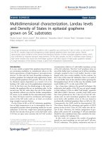
Fig. 2.1—Composite structure at the micro-mechanical level
[Composites Institute/SPI (1994)]
Fig. 2.2—Stress-strain diagram for three epoxy materials
[Schwarz (1992a)]
STRAIN in./in. and mm/mm
FRP REINFORCEMENT
440R-11
posite are; fiber orientation, length, shape and composition
of the fibers, the mechanical properties of the resin matrix,
and the adhesion or bond between the fibers and the matrix.
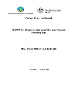
A unidirectional or one-dimensional fiber arrangement is
anisotropic. This fiber orientation results in a maximum
strength and modulus in the direction of the fiber axis. A pla-
nar arrangement of fibers is two-dimensional and has differ-
ent strengths at all angles of fiber orientation. A three-
dimensional array is isotropic but has substantially reduced
strengths over the one-dimensional arrangement. Mechani-
cal properties in any one direction are proportional to the
amount of fiber by volume oriented in that direction as
shown in Fig. 2.3.
2.8.1 Fiber considerations The properties of a fiber-rein-
forced composite depend strongly on the direction of mea-
surement in relationship to the direction of the fibers. Tensile
strength and modulus of a unidirectionally reinforced lami-
nate are maxima when these properties are measured in the
longitudinal direction of the fibers. At other angles, proper-
ties are reduced. Similar angular dependance is observed for
other physical and mechanical properties.
Metals exhibit yielding and plastic deformation or ductili-
ty under load. Most fiber-reinforced composites are elastic in
their tensile stress-strain characteristics. The heterogeneous
nature of fiber/polymer composite materials provides mech-
anisms for high energy absorption on a micro-scale compa-
rable to the metallic yielding process. Depending on the type
and severity of external loads, a composite laminate may ex-
hibit gradual deterioration of properties.
Many fiber-reinforced composites exhibit high internal
damping properties. This leads to better vibrational energy
absorption within the material and reduces transmission to
adjacent structures. This aspect of composite behavior may
be relevant in civil engineering structures (bridges, high-
ways, etc.) that are subject to loads that are more transitory
and of shorter duration than sustained excessive loadings.
2.8.2 Functional relationship of polymer matrix to rein-
forcing fiber—The matrix gives form and protection from
the external environment to the fibers. Chemical, thermal,
and electrical performance can be affected by the choice of
matrix resin. But the matrix resin does much more than this.
It maintains the position of the fibers. Under loading, the ma-
trix resin deforms and distributes the stress to the higher
modulus fiber constituents. The matrix should have an elon-
gation at break greater than that of the fiber. It should not
shrink excessively during curing to avoid placing internal
strains on the reinforcing fibers.
If designers wish to have materials with anisotropic prop-
erties, then they will use appropriate fiber orientation and
forms of uni-axial fiber placement. Deviations from this
practice may be required to accommodate variable cross-
sections and can be made only within narrow limits without
resorting to the use of shorter axis fibers or by alternative fi-
ber re-alignment. Both of these design approaches inevitably
reduce the load-carrying capability of the molded part and
will probably also adversely affect its cost effectiveness. On
the other hand, in the case of a complex part, it may be nec-
essary to resort to shorter fibers to reinforce the molding ef-
fectively in three dimensions. In this way, quasi-isotropic
properties can be achieved in the composite. Fiber orienta-
tion also influences anisotropic behavior as shown in Fig.
2.4.
2.8.3 Effects of fiber length on laminate properties—Fiber
placement can be affected with both continuous and short fi-
bers. Aside from the structural implications noted earlier in
this chapter, there may be part or process constraints which
impose choice limitations on designers. The alternatives in
these cases may require changes in composite part cross sec-
tion area or shape. Variables in continuous-fiber manufac-
ture, as well as in considerations in part fabrication, make it
impossible to obtain equally stressed fibers throughout their
length without resorting to extraordinary measures.
Fig. 2.3—Strength relation to fiber orientation [Schwarz (1992b)]
440R-12 MANUAL OF CONCRETE PRACTICE
2.8.4 Bonding interphase—Fiber composites are able to
withstand higher stresses than can their constituent materials
because the matrix and fibers interact to redistribute the
stresses of external loads. How well the stresses are distrib-
uted internally within the composite structure depends on the
nature and efficiency of the bonding. Both chemical and me-
chanical processes are thought to be operational in any given
structural situation. Coupling agents are used to improve the
chemical bond between reinforcement and matrix since the
fiber-matrix interface is frequently in a state of shear when
the composite is under load.
2.8.5 Design considerations—Although classical stress
analysis and finite element analysis techniques are used, the
design of fiber-reinforced composite parts and structures is
not a “cook book” exercise. These materials are generally
more expensive on a per-pound basis, but are frequently
quite cost competitive on a specific-strength basis (i.e., dol-
lars per unit of load carried, etc.). With the exception of the
higher-cost carbon fibers, the modulus of fiber-reinforced
composites is significantly lower than conventional materi-
als. Therefore, innovative design in respect to shape, fiber
choice, fiber placement, or hybridization with other fibers
must be utilized by designers to take this factor into account.
The following considerations are representative of the
choices which are commonly made:
• Composites are anisotropic and can be oriented in the di-
rection(s) of the load(s) required
• There is a high degree of design freedom. Variations in
thickness and compound part geometry can be molded
into the part
• Compared to traditional designing, with composites
there is usually plenty of tensile (fiber strength) but not
comparable stiffness unless carbon fibers are involved.
In the case of carbon fiber usage, designers may have to
be concerned about impact and brittleness
Table 2.5 may help put these considerations in perspec-
tive.
Additional design considerations which should be consid-
ered include:
• Designing to provide the maximum stiffness with the
minimum materials
Fig. 2.4—Varying fiber orientation in laminate construction
[Schwarz (1992c)]
Fig. 2.5—Tensile stress-strain behavior of various reinforc-
ing fibers (Gerritse and Schurhoff)
Table 2.4—Comparison of properties between reinforced epoxy and selected metals [Mayo (1987)]
Material Density (gr/cm
3
)
Unidirectional strength Unidirectional tensile strength
Tensile, MPa (ksi) Compressive, MPa (ksi) GPa (10
3
ksi)
Carbon AS-4 1.55 1482 (215) 1227 (178) 145 (21.0)
Carbon HMS 1.63 1276 (185) 1020 (148) 207 (30.0)
S-Glass
TM
1.99 1751 (254) 496 (72) 59 (8.6)
E-Glass 1.99 1103 (169) 490 (71) 52 (7.6)
Aramid 1.38 1310 (190) 290 (42) 83 (12.0)
Aluminum (7075-T6) 2.76 572 MPa (83 ksi) 69 (10.0)
Titanium (6A1-4V) 4.42 1103 MPa (160 ksi) 114 (16.5)
Steel (4130) 8.0 1241-1379 MPa (180-220 ksi) 207 (30.0)
FRP REINFORCEMENT
440R-13
• Taking advantage of anisotropic nature of material and
oriented fibers, but making sure that process of manu-
facture is compatible with selections
• Optimizing the maximum strain limitations of the lami-
nate. The elongation of the resin is an important factor
in choosing the matrix resin for a large structural part.
However, the effect of stress crazing and possible stress
corrosion in chemical or environmentally stressful con-
ditions may reduce the long term performance and a
more conservative design may be required. This will al-
low for effects of creep, cracking, aging, deleterious so-
lutions, etc.
• Understanding creep and fatigue properties of the lami-
nate under constant and intermittent loads
• Understanding that, in order to develop the acceptable
properties, the matrix should be able to accept a higher
strain than the reinforcement
• Making sure that the energy stored at failure, which is
the area under the stress/ strain curve, is as large as pos-
sible, since this indicates a “tough” composite
Earlier in this chapter, the stress-strain relationship for
loaded fibers was discussed. Each of the fibers considered
suitable for structural engineering uses have specific elonga-
tion and stress-strain properties. Fig. 2.6 makes the range of
these properties quite graphic.
2.9—Glass fibers
Glass has been the predominant fiber for many civil engi-
neering applications because of an economical balance of
cost and specific strength properties. Glass fibers are com-
mercially available in E-Glass formulation (for electrical
grade), the most widely used general-purpose form of com-
posite reinforcement, high strength S-2
®
glass and ECR
glass (a modified E Glass which provides improved acid re-
sistance). Other glass fiber compositions include AR, R and
Te. Although considerably more expensive than glass, other
fibers including carbon and aramid, are used for their
strength or modulus properties or in special situations as hy-
brids with glass. Properties of common high-performance
reinforcing fibers are shown in Table 2.6.
2.9.1 Chemical composition of glass fiber—Glass fibers
are made with different compositions as noted in Table 2.7,
utilizing glass chemistry to achieve the chemical and physi-
cal properties required.
E-Glass—A family of calcium-alumina-silicate glasses
which has the following certified chemical compositions and
which is used for general-purpose molding and virtually all
electrical applications. E-glass comprises approximately 80
to 90 percent of the glass fiber commercial production. The
nomenclature “ECR-glass” is used for boron-free modified
E-glass compositions. This formulation offers improved re-
Table 2.5—Comparative thickness and weight for equal strength materials [from Parklyn (1971)]
Materials
Equal tensile strength Equal tensile thickness Equal bending stiffness
Thickness Weight Thickness Weight Thickness Weight
Mild steel 1.0 1.0 1.0 1.0 1.0 1.0
Aluminum 1.8 0.3 3.0 1.1 1.5 0.5
GFRP
1
2.4 0.07 25 5.0 3.0 0.6
GFRP
2
0.3 0.1 6.8 1.5 1.9 0.5
1
Based on random fiber orientation.
2
Based on unidirectional fiber orientation.
Fig. 2.6—Glass fiber rovings [Owens-Corning Fiberglass Corporation (1995)]
440R-14 MANUAL OF CONCRETE PRACTICE
sistance to corrosion by most acids.
S-Glass—Is a proprietary magnesium alumino-silicate
formulation that achieves high strength, as well as higher
temperature performance. S-Glass and S-2 Glass have the
same composition, but use different surface treatments. S-
Glass is the most expensive form of glass fiber reinforce-
ment and is produced under specific quality control and sam-
pling procedures to meet military specifications.
C-Glass—Has a soda-lime-borosilicate composition and
is used for its chemical stability in corrosive environments.
It is often used in composites that contact or contain acidic
materials for corrosion-resistant service in the chemical pro-
cessing industry.
2.9.2 Forms of glass fiber reinforcements—Glass fiber-re-
inforced composites contain fibers having lengths far greater
than their cross sectional dimensions (aspect ratios > 10:1).
The largest commercially produced glass fiber diameter is a
“T” fiber filament having a nominal diameter of 22.86 to
24.12 microns. A number of fiber forms are available.
Rovings—This is the basic form of commercial continu-
ous fiber. Rovings are a grouping of a number of strands, or
in the case of so-called “direct pull” rovings, the entire rov-
ing is formed at one time. This results in a more uniform
product and eliminates catenary associated with roving
groups of strands under unequal tension. Fig. 2.6 shows a
photo of continuous roving.
Woven roving—The same roving product mentioned
above is also used as input to woven roving reinforcement.
The product is defined by weave type, which can be at 0 and
90 deg; at 0 deg, +45 deg, -45 deg, and other orientations de-
pending on the manufacturing process. These materials are
sold in weight per square yard. Common weights are 18
oz/yd
2
[(610.3 gr/m
2
) and 24 oz/yd
2
(813.7 gr/m
2
)] (see Fig.
2.7).
Mats—These are two-dimensional random arrays of
chopped strands. The fiber strands are deposited onto a con-
tinuous conveyor and pass through a region where thermo-
setting resin is dusted on them. This resin is heat set and
holds the mat together. The binder resin dissolves in the
polyester or vinyl ester matrix thereby allowing the mat to
conform to the shape of the mold, (see Fig. 2.8).
Combined products—It is also possible to combine a wo-
ven roving with a chopped strand mat. There are several
techniques for accomplishing this. One technique bonds the
two reinforcements together with a thermosetting resin sim-
ilar to that in the chopped strand approach. Another approach
starts with the woven roving but has the chopped strand fi-
bers deposited onto the surface of the woven roving, which
is followed immediately by a stitching process to secure the
chopped fibers. There are several variations on this theme.
Cloth—Cloth reinforcement is made in several weights as
measured in ounces-per-square-yard. It is made from contin-
uous strand filaments that are twisted and plied and then wo-
ven in conventional textile processes (see Fig. 2.9).
All composite reinforcing fibers, including glass, will be
anisotropic with respect to their length. There are fiber place-
ment techniques and textile-type operations that can further
arrange fibers to approach a significant degree of quasi-iso-
Table 2.6—Comparison of inherent properties of fibers (impregnated strand per ASTM D 2343) [Owens-Corning
Corp. (1993)]
Specific gravity
Tensile strength Tensile modulus
MPa 10
3
psi GPa 10
6
psi
E-glass 2.58 2689 390 72.4 10.5
S-2-glass® 2.48 4280 620 86.0 13.0
ECR-Glass* 2.62 3625 525 72.5 10.5
K-49 Aramid 1.44 3620 525 131.0 19.0
AS4 Carbon 1.80 3790 550 234.0 34.0
* Mechanical properties—single filament at 72 F per ASTM D 2101
Table 2.7—Compositional ranges for commercial glass fibers (units = perccent by weight)
E-glass range S-glass range C-glass range
Silicon dioxide 52-56 65 64-68
Aluminum oxide 12-16 25 3-5
Boric oxide 5-10 — 4-6
Sodium oxide and potassium oxide 0-2 — 7-10
Magnesium oxide 0-5 10 2-4
Calcium oxide 16-25 — 11-25
Barium oxide — — 0-1
Zinc oxide — — —
Titanium oxide 0-1.5 — —
Zirconium oxide — — —
Iron oxide 0-0.8 — 0-0.8
Iron 0-1 — —
FRP REINFORCEMENT
440R-15
tropic composite performance. Glass fibers and virtually all
other composite fibers are also available in a range of fabric-
like forms including braided (see Terminology in Appendix
A), needle punched, stitched, knitted, bonded, multi-axial,
and multiple-ply materials.
2.9.3 Other glass fiber considerations—Glass fibers are
very surface-active and are hydrophilic. They can be easily
damaged in handling. A protective film former is applied im-
mediately as the first step after the fiber-forming process.
Sizing solutions containing the film former also contain an
adhesion promoter. Adhesion promoters are usually organo-
functional silanes, which function as coupling agents.
The film former also provides processability and moisture
protection. The adhesion promoter acts to improve the cou-
pling between the fiber and the polymer resin matrix. Fiber
suppliers select their adhesion promoters and film formers
depending on the matrix resins and manufacturing/process-
ing parameters of the intended product.
2.9.4 Behavior of glass fibers under load—Glass fibers
are elastic until failure and exhibit negligible creep under
controlled dry conditions. Generally, it is agreed that the
modulus of elasticity of mono-filament E-glass is approxi-
mately 73 GPa. The ultimate fracture strain is in the range of
2.5 to 3.5 percent. The stress-strain characteristics of strands
have been thoroughly investigated. The general pattern of
the stress-strain relationship for glass fibers was illustrated
earlier in Fig. 2.4. The fracture of the actual strand is a cumu-
lative process in which the weakest fiber fails first and the
load is then transferred to the remaining stronger fibers
which fail in succession.
Glass fibers are much stronger than a comparable glass
formulation in bulk form such as window glass, or bottle
glass. The strength of glass fibers is well-retained if the fi-
bers are protected from moisture and air-borne or contact
contamination.
When glass fibers are held under a constant load at stresses
below the instantaneous static strength, they will fail at some
point as long as the stress is maintained above a minimum
value. This is called “creep rupture.” Atmospheric condi-
tions play a role, with water vapor being most deleterious. It
has been theorized that the surface of glass contains submi-
croscopic voids that act as stress concentrations. Moist air
can contain weakly acidic carbon dioxide. The corrosive ef-
fect of such exposure can affect the stress in the void regions
for glass fiber filaments until failure occurs. In addition, ex-
posure to high pH environments may cause aging or a rup-
ture associated with time.
These potential problems were recognized in the early
years of glass fiber manufacture and have been the object of
continuing development of protective treatments. Such treat-
ments are universally applied at the fiber-forming stage of
manufacture. A number of special organo-silane functional
treatments have been developed for this purpose. Both multi-
functional and environmental-specific chemistries have been
developed for the classes of matrix materials in current use.
Depending upon the resin matrix used, the result of these de-
velopments has been to limit the loss of strength to 5 to 10
percent after a 4-hr water boil test.
2.10—Carbon fibers
There are three sources for commercial carbon fibers:
Fig. 2.7—Glass fiber woven rovings [Owens-Corning Cor-
poration (1995)]
Fig. 2.8—Glass fiber chopped strand mat [Owens-Corning
Fiberglass Corporation (1995)]
Fig. 2.9—Glass fiber cloth during weaving and inspection
[Clark-Schwebel, Inc. (1995)]
440R-16 MANUAL OF CONCRETE PRACTICE
pitch, a by-product of petroleum distillation; PAN (poly-
acrylonitrile), and rayon. The properties of carbon fiber are
controlled by molecular structure and degree of freedom
from defects. The formation of carbon fibers requires pro-
cessing temperatures above 1830 F (1000 C). At this temper-
ature, most synthetic fibers will melt and vaporize. Acrylic,
however, does not and its molecular structure is retained dur-
ing high-temperature carbonization.
There are two types of carbon fiber: the high modulus
Type I and the high strength Type II. The difference in prop-
erties between Types I and II is a result of the differences in
fiber microstructure. These properties are derived from the
arrangement of the graphene (hexagonal) layer networks
present in graphite. If these layers are present in three-di-
mensional stacks, the material is defined as graphite. If the
bonding between layers is weak and two-dimensional layers
occur, the resulting material is defined as carbon. Carbon fi-
bers have two-dimensional ordering.
Table 2.8—Typical properties of commercial composite reinforcing fibers [constructed from Mallick (1988b) and Akzo-
Nobel (1994)]
Fiber
Typical diameter
(microns) Specific gravity
Tensile modulus
GPa (10
6
psi)
Tensile strength
GPa (10
3
psi)
Strain to failure,
percent
Coefficient of
thermal expansion
10
-6
/C Poisson’s ratio
Glass
E-glass 10 2.54 72.4 (10.5) 3.45 (500.0) 4.8 5.0 0.2
S-glass 10 2.49 86.9 (12.6) 4.30 (625.0) 5.0 2.9 0.22
Carbon
PAN-Carbon
T-300
a
7 1.76 231 (33.5) 3.65 (530) 1.4
-0.1 to -0.5 (longi-
tudinal), 7-12
(radial) -0.2
AS
b
7 1.77 220 (32) 3.1 (450) 1.2
-0.5 to -1.2 (longi-
tudinal), 7-12
(radial) —
t-40
a
6 1.81 276 (40) 5.65 (820) 2.0 — —
HSB
b
7 1.85 344.5 (50) 2.34 (340) 0.58 — —
Fortafil 3
TM C
7 1.80 227 (33) 3.80 (550) 1.7 -0.1 —
Fortafil 5
TM C
7 1.80 345 (50) 2.76 (400) 0.8 — —
PITCH-Carbon
P-555
a
10 2.0 380 (55) 1.90 (275) 0.5 -0.9 (longitudinal) —
P-100
a
10 2.16 758 (110) 2.41 (350) 0.32 -1.6 (longitudinal) —
ARAMID
Kevlar
TM
49
d
11.9 1.45 131 (19) 3.62 (525) 2.8
-2.0 (longitudinal)
+59 (radial) 0.35
Twaron
TM
1055
e*
12.0 1.45 127 (18) 3.6 (533) 2.5
-2.0 (longitudinal)
+59 (radial) 0.35
a
Amoco
b
Hercules
c
Akzo-Nobel/Fortafil fibers
d
DuPont de Nemours and Co.
e
Akzo-Nobel Fibers
*
Minimum lot average values.
Table 2.9—Properties of ARAMID yarn and reinforcing fibers [constructed from DuPont (1994) and Akzo-Nobel
(1994)]
Property Kevlar 49
Twaron 1055
*
Yarn
Tensile strength MPa (ksi) 2896 (420.0) 2774 (398.0)
Tenacity dN/tex (g/den) 20.4 (23) 19.0 (21.4)
Modulus GPa (ksi) 117.2 (17,000) 103.4 (15,000)
Elongation at break, percent 2.5 (2.5) 2.5 (2.5)
Density g/cm
3
(lb/in.
3
)
1.44 (0.052) 1.45 (0.052)
Reinforcing fibers
Tensile strength MPa (ksi) 3620 (525.0) 3599 (522.0)
Modulus GPa (ksi) 124.1 (18,000) 127.0 (18,420)
Elongation at break, percent 2.9 (2.9) 2.5 (2.5)
Density g/cm
3
(lb/in.
3
)
1.44 (0.052) 1.45 (0.052)
* Minimum lot average values.
FRP REINFORCEMENT
440R-17
High modulus carbon fibers of 200GPa (30 x 10
6
psi) re-
quire that stiff graphene layers be aligned approximately par-
allel to the fiber axis.
Rayon and isotropic pitch precursors are used to produce
low modulus carbon fibers (50 GPa or 7 x 10
6
psi). Both
PAN and liquid crystalline pitch precursors are made into
higher modulus carbon fibers by carbonizing above 1400 F
(800 C). Fiber modulus increases with heat treatment from
1830 F to 5430 F (1000 C to 3000 C). The results vary with
the precursor selected. Fiber strength appears to maximize at
a lower temperature 2730 F (1500 C) for PAN and some
pitch precursor fibers, but increases for most mesophase
(anisotropic) pitch precursor fibers.
The axial-preferred orientation of graphene layers in car-
bon fibers determines the modulus of the fiber. Both axial
and radial textures and flaws affect the fiber strength. Orien-
tation of graphene layers at the fiber surface affects wetting
and strength of the interfacial bond to the matrix.
Carbon fibers are not easily wet by resins; particularly the
higher modulus fibers. Surface treatments that increase the
number of active chemical groups (and sometimes roughen
the fiber surface) have been developed for some resin matrix
materials. Carbon fibers are frequently shipped with an ep-
oxy size treatment applied prevent fiber abrasion, improve
handling, and provide an epoxy resin matrix compatible in-
terface. Fiber and matrix interfacial bond strength approach-
es the strength of the resin matrix for lower modulus carbon
fibers. However, higher modulus PAN-based fibers show
substantially lower interfacial bond strengths. Failure in high
modulus fiber occurs in its surface layer in much the same
way as with aramids.
2.10.1 Commercial forms of carbon fibers—Carbon fibers
are available as “tows” or bundles of parallel fibers. The
range of individual filaments in the tow is normally from
1000 to 200,000 fibers. Carbon fiber is also available as a
prepreg, as well as in the form of unidirectional tow sheets.
Typical properties of commercial carbon fibers are shown
in Table 2.8.
2.11—Aramid fibers
There are several organic fibers available that can be used
for structural applications. However, cost, and in some cases
service temperature or durability factors, restrict their use to
specific applications. The most popular of the organic fibers
is aramid. The fiber is poly-para-phenyleneterephthalamide,
known as PPD-T. Aramid fibers are produced commercially
by DuPont (Kevlar™) and Akzo Nobel (Twaron™).
These fibers belong to the class of liquid crystal polymers.
These polymers are very rigid and rod-like. The aromatic
ring structure contributes high thermal stability, while the
para configuration leads to stiff, rigid molecules that contrib-
ute high strength and high modulus. In solution they can ag-
gregate to form ordered domains in parallel arrays. More
conventional flexible polymers in solutions bend and entan-
gle, forming random coils.
When PPD-T solutions are extruded through a spinneret
and drawn through an air gap during manufacture, the liquid
crystal domains can align in the direction of fiber flow. The
fiber structure is anisotropic, and presents higher strength
and modulus in the longitudinal direction than in the axial
transverse direction. The fiber is also fibrillar (it is thought
that tensile failure initiates at fibril ends and propagates via
shear failure between the fibrils).
2.11.1 Material properties of aramid—Representative
properties of para-aramid (p-aramid) fibers are given below.
Kevlar 49 and Twaron 1055 are the major forms used today
because of higher modulus. Kevlar 29 and Twaron 2000 are
used for ballistic armor and applications requiring increased
toughness. Ultra-high modulus Kevlar 149 is also available.
Aramid fibers are available in tows, yarns, rovings, and var-
ious woven cloth products. These can be further processed to
intermediate stages, such as prepregs. Detailed properties of
aramid fibers are shown in Table 2.9.
• Tensile modulus is a function of molecular orientation
• Tensile strength: Para-aramid fiber is 50 percent stron-
ger than E glass. High modulus p-aramid yarns show a
linear decrease of both tensile strength and modulus
when tested at elevated temperature. More than 80 per-
cent of strength is retained after temperature condition-
ing
• At room temperature the effect of moisture on tensile
properties is < 5 percent
• Creep and fatigue: Para-aramid is resistant to fatigue
and creep rupture
• Creep rate is low and similar to that of fiberglass. It is
less susceptible to creep rupture
• Compressive properties: Para-aramid exhibits nonlin-
ear, ductile behavior under compression. At a compres-
sion strain of 0.3 to 0.5 percent, a yield is observed. This
corresponds to the formation of structural defects
known as kink bands, which are related to compressive
buckling of p-aramid molecules. This compression be-
havior limits the use of p-aramid fibers in applications
that are subject to high strain compressive or flexural
loads
• Toughness: Para-aramid fiber’s toughness is related di-
rectly to conventional tensile toughness, or area under
the stress-strain curve. The p-aramid fibrillar structure
and compressive behavior contribute to composites that
are less notch sensitive
• Thermal properties: The p-aramid structure results in a
high degree of thermal stability. Fibers will decompose
in air at 800 F (425 C). They have utility over the tem-
perature range of -200 C to 200 C, but are not used
long-term at temperatures above 300 F (150 C) because
of oxidation. The fibers have a slightly negative longi-
tudinal coefficient of thermal expansion of -2 x 10 -6/K
• Electrical properties: Para-aramid is an electrical insu-
lator. Its dielectric constant is 4.0 measured at 106 Hz
• Environmental behavior: Para-aramid fiber can be de-
graded by strong acids and bases. It is resistant to most
other solvents and chemicals. UV degradation can also
occur. In polymeric composites, strength loss has not
been observed
One caution concerns the compressive behavior noted
above, which results in local crumpling and fibrillation of in-
440R-18 MANUAL OF CONCRETE PRACTICE
dividual fibers, thus leading to low strength under conditions
of compression and bending. For this reason aramids are un-
suitable, unless hybridized with glass or carbon fiber, for use
in FRP shell structures which have to carry high compressive
or bending loads. Such hybridized fiber structures lead to a
high vibration damping factor which may offer advantages
in dynamically loaded FRP structures.
2.12—Other organic fibers
Ultra-high-molecular-weigh t-polyethyl ene fibers—One
fiber of this type manufactured and marketed by Allied Sig-
nal Corp. in the United States is called Spectra™. It was
originally developed in the Netherlands by DSM (Dutch
State Mines).
Table 2.10 shows the properties of Spectra ultra-high-mo-
lecular-weight polyethylene fibers. The major applications
for Spectra have been in rope, special canvas and woven
goods, and ballistic armor. Its lightness combined with
strength and low tensile elongation make it attractive for
these uses. Drawbacks include fiber breakdown at tempera-
tures above 266 F (130 C). None of the current resin matrix
materials bond well to this fiber. Plasma treatment has been
used to etch the surface of the fibers for a mechanical bond
to the resin matrix, but this is expensive, and is not readily
available in commercial production.
2.13—Hybrid reinforcements
It should be apparent that properties of the fibers differ sig-
nificantly. The so-called high-performance fibers also carry
high performance price tags.
These materials can be combined in lamina, and in uniax-
ial arrangements as hybrids to give appropriate properties at
an acceptable cost. The infrastructure applications are natu-
ral opportunities for evaluation and utilization of such com-
binations. Table 2.11 illustrates the results that can be
obtained.
Both polymer matrix resin and reinforcement exercise an
interactive effect on the fabrication used to join composite
materials, forming the finished part.
2.14—Processes for structural moldings
There are several methods of achieving reliable fiber
placement. These methods can be considered process-specif-
ic (i.e., the nature of the forming process and/or its contin-
gent tooling largely controls the fabricated result). In this
category are the common commercial fabricating processes.
Filament winding—This process takes continuous fibers
Fig. 2.10—Filament winding process [Mettes (1969e)]
Table 2.10—Properties of spectra
TM
fibers [from Pigliacampi (1987)]
Spectra 900 Spectra 1000
Density gr/cm
3
(lb/in.
3
)
0.97 (0.035) 0.97 (0.035)
Filament diameter m (in.) 38 (1500) 27 (1060)
Tensile modulus GPa (10
6
psi)
117 (17) 172 (25)
Tensile strength GPa (10
6
psi)
2.6 (0.380) 2.9-3.3 (0.430-0.480)
Tensile elongation, percent 3.5 2.7
Available yarn count ( number of filaments) 60-120 60-120
Table 2.11—Properties of carbon-glass-polyester hybrid composites* [from Schwarz (1992e)]
Carbon/glass ratio
Tensile strength,
MPa (ksi)
Modulus of elasticity
(tension), GPa
(10
6
psi)
Flexural strength,
MPa (ksi)
Flexural modulus,
GPa (10
6
psi)
Interlaminar shear
strength, MPa (ksi)
Density, gr/cm
3
(lbs/in.
3
)
0:100 604.7 (87.7) 40.1 (5.81) 944.6 (137) 35.4 (5.14) 65.5 (9.5) 1.91 (0.069)
25:75 641.2 (93.0) 63.9 (9.27) 1061.8 (154) 63.4 (9.2) 74.5 (10.8) 1.85 (0.067)
50:50 689.5 (100) 89.6 (13.0) 1220.4 (177) 78.6 (11.4) 75.8 (11.0) 1.80 (0.065)
75:25 806.7 (117) 123.4 (17.9) 1261.7 (183) 1261.7 (16.3) 82.7 (12.0) 1.66 (0.060)
* Fiber contents are by volume. Resin is 48 percent Thermoset Polyester, plus 52 percent continuous unidirectional oriented fiber by volume, equivalent to 30 percent resin and 70
percent fiber by weight. Properties apply to longitudinal fiber direction only.
1 ksi = 6.895 MPa; 1 lb/in.
3
= 0.0361 g/cm
3
.
FRP REINFORCEMENT
440R-19
in the form of parallel strands (rovings), impregnates them
with matrix resin and winds them on a rotating cylinder. The
resin-impregnated rovings are made to traverse back and
forth along the length of the cylinder. A controlled thickness,
wind angle, and fiber volume fraction laminate is thereby
created. The material is cured on the cylinder and then re-
moved (see Fig. 2.10).
Pipe, torsion tubes, rocket cases, pressure bottles, storage
tanks, airplane fuselages, and the like are made by this pro-
cess. The moving relationship between the rotating surface
and the roving/matrix is usually controlled by computer.
There can be additional add-on fiber/matrix placement sys-
tems to add chopped short-length fibers and/or particulate
materials to increase thickness at low cost. Polyester, vinyl
ester, and epoxy matrix materials are used.
Pultrusion—This process makes a constant cross-section
part of unlimited length which is constrained only by build-
ing and shipping limitations. The pultrusion process uses
continuous fibers from a series of creel positions (see Termi-
nology in Appendix A). All the fiber rovings necessary for
the cross-section of the part are drawn to a wet-out bath that
contains the resin matrix, catalyst (or hardener), and other
additives. The rovings are impregnated in the bath. Excess
liquid resin is removed and returned to the bath, while the
wet-out roving enters the pultrusion die. These dies are gen-
erally 36 in. to 48 in. (0.9-1.3 m) long and are heated electri-
cally or by hot oil. In some cases, a radio-frequency (RF)
preheating cabinet is employed to increase the ease of curing
thick sections. Throughput rate is generally about 0.9 m (36
linear in.) per min. Complex and thick sections may take
more time to affect complete cure while very thin sections
may take less time. Polyester resin and vinyl esters are the
major matrix materials used in the pultrusion process (Fig.
2.11).
Examples of products produced by pultrusion include oil
well sucker rods; tendons for prestressing and post-tension-
ing concrete; concrete formties; structural shapes for me-
chanical fabrication used in offshore drilling rigs, and
chemical processing plants; grating; third rail covers; auto-
mobile drive shafts; ground anchors and tie backs; sheet pil-
ing, and window frame sections.
Vacuum compaction processes—This is a family of pro-
cesses in which the weight of the atmosphere can work
against a materials system that has been sufficiently evacu-
ated of entrapped air to allow compression and compaction
of the uncured laminate to take place. In some forms of the
process, a pre-impregnated arrangement of fibers is placed
on a mold in one or more lamina thicknesses. A covering
sheet of stretchable film is placed over the lamina array and
secured to the mold surface. A vacuum is drawn from within
the covered area by a hose leading to a vacuum pump. As the
air is evacuated, the stretchable sheet is pressed against the
fiber/prepreg array to compact the lamina. The entrapped air
is thereby removed from between the laminae plies. If the
resin matrix is heated by one of a number of methods, (infra-
red lamps, heated mold, steam autoclave, etc.), the resin vis-
cosity drops and additional resin densification can take place
before the increase in resin viscosity associated with curing
(Fig. 2.12).
Other processes use vacuum to compact a dry fiber array
on the mold. This allows the resin to flow into the evacuated
mechanical spaces between and among the fibers. This is
easier said than accomplished. There are several modifica-
Fig. 2.11—Pultrusion process [Creative Pultrusions, Inc. (1994)]
Fig. 2.12—Vacuum compaction processing [Schwarz
(1992f)]
440R-20 MANUAL OF CONCRETE PRACTICE
Table 3.1—Comparison of mechanical properties (longitudinal direction)
Steel reinforcing bar Steel tendon GFRP bar GFRP tendon CFRP tendon AFRP tendon
Tensile strength, MPa
(ksi)
483-690
70-100
1379-1862
200-270
517-1207
75-175
1379-1724
200-250
165-2410
240-350
1200-2068
170-300
Yield strength, MPa
(ksi)
276-414
40-60
1034-1396
150-203 Not applicable
Tensile elstic modu-
lus, GPa (ksi)
200
29,000
186-200
27,000-29,000
41-55
6000-8000
48-62
7000-9000
152-165
22,000-24,000
50-74
70,000-11,000
Ultimate elongation,
mm/mm > 0.10 >0/04 0.035-0.05 0.03-0.045 0.01-0.015 0.02-0.026
Compressive
strength, MPa (ksi)
276-414
40-60 N/A
310-482
45-70 N/A N/A N/A
Coefficient of
thermal expansion
(10
-6
/C) (10
-6
/F)
11.7
6.5
11.7
6.5
9.9
5.5
9.9
5.5
0.0
0.0
-1.0
-0.5
Specific gravity 7.9 7.9 1.5-2.0 2.4 1.5-1.6 1.25
Note: All properties refer to unidirectional reinforced coupons. Properties vary with the fiber volume (45-70 percent), coupon diameter, and grip system.
N/A = Not available.
tions of this methodology that can allow the resin to flow
through the compacted fiber arrays. Most of these methods
utilize auxiliary resin distribution schemes and positive
spacing methods to keep the stretch film from clamping off
the flow of resin prematurely. Resin cure is described above.
There are currently demonstration processes of this type
which appear to be suitable for making very large moldings
in this manner. Note that this process does not require a
molding press, only a single-sided tool.
Matched mold processes—This system includes a range of
process materials. However, several characteristics are
shared:
• The molds define the shape and thickness of the part, so
they must have a means of being reproducibly reposi-
tioned for each part. In most cases this implies a press
of some sort.
• The practical limit on the size of the press, plane area
and openings. Pressing forces depending on the materi-
al system in the range of 30 to 900 psi (0.21- 6.21 MPa)
will be required. The lower number is associated with
Resin Transfer Molding (RTM), and the higher number
is common for Sheet Molding Compound. Also, these
systems generally use short fibers, in three dimensional
arrays, and properties will be quasi-isotropic, and much
lower than the anisotropic arrays of continuous long fi-
bers.
2.15—Summary
In this chapter, the major materials used in composite sys-
tems were identified and discussed. The interactions be-
tween the form and physical nature of these materials and the
molding processes, a relationship somewhat unique to struc-
tural composites, were discussed. This interaction should be
kept in mind to continually remind the structural practitioner
of the potential efficiency and cost trade-offs available with
composites. When one chooses composite materials without
sufficient regard for the inter-relationship of materials, form
of materials, and processing, the result may be overly expen-
sive, structurally ineffective, or difficult to fabricate.
CHAPTER 3—MECHANICAL PROPERTIES
AND TEST METHODS
3.1—Physical and mechanical properties
In discussions related to the properties of FRP bars or ten-
dons, the following points must be kept in mind. First, an
FRP bar is anisotropic, with the longitudinal axis being the
strong axis. Second, unlike steel, mechanical properties of
FRP composites vary significantly from one product to an-
other. Factors such as volume and type of fiber and resin, fi-
ber orientation, dimensional effects, and quality control
during manufacture, play a major role in establishing prod-
uct characteristics. Furthermore, the mechanical properties
of FRP composites, like all structural materials, are affected
by such factors as loading history and duration, temperature,
and moisture.
While standard tests have been established to determine
the properties of traditional construction materials, such as
steel and concrete, the same cannot be said for FRP materi-
als. This is particularly true for civil engineering applica-
tions, where the use of FRP composites is in its stage of
infancy. It is therefore required that exact loading conditions
be determined in advance and that material characteristics
corresponding to those conditions be obtained in consulta-
tion with the manufacturer.
3.1.1 Specific gravity—FRP bars and tendons have a spe-
cific gravity ranging from 1.5 to 2.0 as they are nearly four
times lighter than steel. The reduced weight leads to lower
transportation and storage costs and decreased handling and
installation time on the job site as compared to steel reinforc-
ing bars. This is an advantage that should be included in any
cost analysis for product selection.
3.1.2 Thermal expansion—Reinforced concrete itself is a
composite material, where the reinforcement acts as the
strengthening medium and the concrete as the matrix. It is
therefore imperative that behavior under thermal stresses for
the two materials be similar so that the differential deforma-
tions of concrete and the reinforcement are minimized. De-
pending on mix proportions, the linear coefficient of thermal
FRP REINFORCEMENT
440R-21
expansion for concrete varies from 6 to 11 x 10
-6
per C (4 to
6 x 10
-6
per F) (Mindess et al. 1981). Listed in Table 3.1 are
the coefficients of thermal expansion for typical FRP prod-
ucts.
3.1.3 Tensile strength—FRP bars and tendons reach their
ultimate tensile strength without exhibiting any material
yielding. A comparison of the properties of FRP and steel re-
inforcing bars and tendons is shown in Table 3.1. The me-
chanical properties of FRP reported here are measured in the
longitudinal (i.e. strong) direction. Values reported for FRP
materials cover some of the more commonly available prod-
ucts.
Unlike steel, the tensile strength of FRP bars is a function
of bar diameter. Due to shear lag, fibers located near the cen-
ter of the bar cross section are not subjected to as much stress
as those fibers that are near the outer surface of the bar (Faza
1991). This phenomenon results in reduced strength and ef-
ficiency in larger diameter bars. For example, for GFRP re-
inforcement produced by one U.S. manufacturer, the tensile
strength ranges from nearly 480 MPa (70 ksi) for 28.7 mm
(No. 9) bars to 890 MPa (130 ksi) for 9.5 mm (No. 3) bars
(Ehsani et al. 1993).
Some FRP tendons were made by stranding seven GFRP
(S-2 Glass) or CFRP pultruded bars of diameter ranging
from 3 to 4 mm (0.125 to 0.157 in.). The ultimate strength of
these tendons was comparable to that of a steel prestressing
strand. For GFRP tendons, ultimate strength varied from
1380 to 1724 MPa (200 to 250 ksi); while for CFRP tendons,
it varied from 1862 to 2070 MPa (270 to 300 ksi) (Iyer and
Anigol 1991).
3.1.4Tensile elastic modulus—As noted in Table 3.1, the
longitudinal modulus of elasticity of GFRP bars is approxi-
mately 25 percent that of steel. The modulus for CFRP ten-
dons, which usually employ stiffer fibers, is higher than that
of GFRP reinforcing bars.
3.1.5 Compressive strength—FRP bars are weaker in
compression than in tension. This is the result of difficulties
in accurately testing unidirectional composites in compres-
sion, and is related to gripping and aligning procedures, and
also to stability effects of fibers. However, the compressive
strength of FRP composites is not a primary concern for
most applications. The compressive strength also depends
on whether the reinforcing bar is smooth or ribbed. Com-
pressive strength in the range of 317 to 470 MPa (46 to 68
ksi) has been reported for GFRP reinforcing bars having a
tensile strength in the range of 552 to 896 MPa (80 to 130
ksi) (Wu 1990). Higher compressive strengths are expected
for bars with higher tensile strength.
3.1.6 Compressive elastic modulus—Unlike tensile stiff-
ness, compressive stiffness varies with FRP reinforcing bar
size, type, quality control in manufacturing, and length-to-
diameter ratio of the specimens. The compressive stiffness
of FRP reinforcing bars is smaller than the tensile modulus
of elasticity. Based on tests of samples containing 55 to 60
percent volume fraction of continuous E-glass fibers in a ma-
trix of vinyl ester or isophthalic resin, a modulus of 34 to 48
GPa (5000 to 7000 ksi) has been reported (Wu 1990). Anoth-
er manufacturer reports the compressive modulus at 34 GPa
(5000 ksi) which is approximately 77 percent of the tensile
modulus for the same product (Bedard 1992).
3.1.7 Shear strength—In general, shear strength of com-
posites is very low. FRP bars, for example, can be cut very
easily in the direction perpendicular to the longitudinal axis
with ordinary saws. This shortcoming can be overcome in
most cases by orienting the FRP bars such that they will re-
sist the applied loads through axial tension. Shear tests using
a full-scale Isoipescu test procedure have been developed
(Porter et al. 1993). This shear test procedure has been ap-
plied successfully to obtain shear properties for FRP dowel
bars on over 200 specimens.
3.1.8 Creep and creep rupture—Fibers such as carbon and
glass have excellent resistance to creep, while the same is not
true for most resins. Therefore, the orientation and volume of
fibers have a significant influence on the creep performance
of reinforcing bars and tendons. One study reports that for a
high-quality GFRP reinforcing bar, the additional strain
caused by creep was estimated to be only 3 percent of the ini-
tial elastic strain (Iyer and Anigol 1991).
Under loading and adverse environmental conditions, FRP
reinforcing bars and tendons subjected to the action of a con-
stant load may suddenly fail after a time, referred to as the
endurance time. This phenomenon, known as creep rupture,
exists for all structural materials including steel. For steel
prestressing strands, however, this is not of concern. Steel
can endure the typical tensile loads, which are about 75 per-
cent of the ultimate strength, indefinitely without any loss of
strength or fracture. As the ratio of the sustained tensile
stress to the short-term strength of the FRP increases, endur-
ance time decreases. Creep tests were conducted in Germany
on GFRP composites with various cross sections. These
studies indicate that creep rupture does no occur if sustained
stress is limited to 60 percent of the short-term strength
(Budelmann and Rostasy 1993).
The above limit on stress may be of little concern for most
reinforced concrete structures since the sustained stress in
the reinforcement is usually below 60 percent. It does, how-
ever, require special attention in applications of FRP com-
posites as prestressing tendons. It must be noted that other
factors, such as moisture, also impair creep performance and
may result in shorter endurance time.
Short-term (48 hr) and long-term (1 year) sustained load
corresponding to 50 percent of the ultimate strength was ap-
plied to GFRP and CFRP tendons at room temperature. The
specimens showed very little creep. Tensile modulus and ul-
timate strength after the test did not change significantly
(Anigol 1991, and Khubchandani 1991).
3.1.9 Fatigue—FRP bars exhibit good fatigue resistance.
Most research in this regard has been on high-modulus fibers
(e.g., aramid and carbon), which were subjected to large cy-
cles of tension-tension loading in aerospace applications. In
tests where the loading was repeated for 10 million cycles, it
was concluded that carbon-epoxy composites have better fa-
tigue strength than steel, while the fatigue strength of glass
composites is lower than steel at a low stress ratio (Schwarz
1992). Other research (Porter et al. 1993) showed good fa-
tigue resistance of GFRP dowel bars in shear subjected to 10
440R-22 MANUAL OF CONCRETE PRACTICE
million cycles. In another investigation, GFRP bars con-
structed for prestressing applications were subjected to re-
peated cyclic loading with a maximum stress of 496 MPa (72
ksi) and a stress range of 345 MPa (50 ksi). The bars could
stand more than 4 million cycles of loading before failure
initiated at the anchorage zone (Franke 1981).
CFRP tendons exhibited good fatigue resistance as shown
in the tension-tension fatigue test for 2 million cycles. The
mean stress was 60 percent of the ultimate strength with min-
imum and maximum stress levels of 55 and 64 percent of the
ultimate strength. The modulus of elasticity of the tendons
did not change after the fatigue test (Gorty 1994).
3.2—Factors affecting mechanical properties
Mechanical properties of composites are dependent on
many factors including load duration and history, tempera-
ture, and moisture. These factors are interdependent and,
consequently, it is difficult to determine the effect of each
one in isolation while the others are held constant.
3.2.1 Moisture—Excessive absorption of water in com-
posites could result in significant loss of strength and stiff-
ness. Water absorption produces changes in resin properties
and could cause swelling and warping in composites. It is
therefore imperative that mechanical properties required of
the composites be determined under the same environmental
conditions where the material is to be used. There are, how-
ever, resins which are formulated to be moisture-resistant
and may be used when a structure is expected to be wet at all
times. In cold regions, the effect of freeze-thaw cycles must
also be considered.
3.2.2 Fire and temperature—Many composites have good
to excellent properties at elevated temperatures. Most com-
posites do not burn easily. The effect of high temperature is
more severe on resin than on fiber. Resins contain large
amounts of carbon and hydrogen, which are flammable, and
research is continuing on the development of more fire-resis-
tant resins (Schwarz 1992). Tests conducted in Germany
have shown that E-glass FRP bars could sustain 85 percent
of their room-temperature strength, after half an hour of ex-
posure to 300 C (570 F) temperature while stressed to 50 per-
cent of their tensile strength (Franke 1981). While this
performance is better than that of prestressing steel, the
strength loss increases at higher temperatures and approach-
es that of steel.
The problem of fire for concrete members reinforced with
FRP composites is different from that of composite materials
subjected to direct fire. In this case, the concrete serves as a
barrier to protect the FRP from direct contact with flames.
However, as the temperature in the interior of the member
increases, the mechanical properties of the FRP may change
significantly. It is therefore recommended that the user ob-
tain information on the performance of a particular FRP re-
inforcement and resin system at elevated temperatures when
potential for fire is high.
3.2.3 Ultraviolet rays—Composites can be damaged by
the ultraviolet rays present in sunlight. These rays cause
chemical reactions in a polymer matrix, which can lead to
degradation of properties. Although the problem can be
solved with the introduction of appropriate additives to the
resin, this type of damage is not of concern when FRP ele-
ments are used as internal reinforcement for concrete struc-
tures, and therefore not subjected to direct sunlight.
3.2.4 Corrosion—Steel reinforcement corrodes and the in-
crease in material volume produces cracks and spalling in
concrete to accelerate further deterioration. A major advan-
tage of composite materials is that they do not corrode. It
must be noted, however, that composites can be damaged as
a result of exposure to certain aggressive environments.
While GFRP bars have high resistance to acids, they can de-
teriorate in an alkaline environment. In a recently completed
study for prestressed concrete applications, a particular type
of glass-epoxy FRP strand embedded in concrete was sub-
jected to salt water tidal simulation, which resulted in water
gain and loss of strength (Sen et al. 1993). Although these re-
sults cannot be generalized, they highlight the importance of
the selection of the correct fiber-resin system for a particular
application. FRP tendons made of carbon fibers are resistant
to most chemicals (Rostasy et al. 1992).
3.2.5 Accelerated aging—Short-term need for long-term
weathering data has necessitated the creation of such analyt-
ical techniques as accelerated aging to predict the durability
of composite structures subjected to harsh environments
over time. Research done at Pilkington Bros. (Proctor et al.
1982) shows that long-term aging predictions, made over a
very short period of time and at higher temperatures corre-
late well with real weather aging. Based on these findings,
researchers (Porter et al. 1992) developed two equations for
accelerated aging of FRP composites. The first equation
gave an acceleration factor based on the mean annual tem-
perature of a particular climate. The second equation showed
a relationship between bath temperature and number of ac-
quired accelerated aging days per day in the bath (Lorenz
1993, Porter et al. 1992). By using these two equations, dow-
el bars composed of E-glass fibers encapsulated in a vinyl es-
ter resin were aged at an elevated temperature of 60 C (140
F) for nine weeks. Specimens were aged in water, lime, and
salt bath solutions. An accelerated aging period of 63.3 days
at an elevated temperature of 60 C (140 F) in the solutions
was utilized without appreciable degradation for a lime bath.
This accelerated aging was equivalent to approximately 50
years.
3.3—Gripping mechanisms
The design and development of a suitable gripping mech-
anism for FRP bars in tension tests and in pre and post-ten-
sioned concrete applications have presented major
difficulties to researchers and practitioners. Due to the low
strength of FRP reinforcing bars and tendons in the trans-
verse direction, the forces introduced by the grips can result
in localized failure of the FRP within the grip zone. Clearly,
the use of longer grips to reduce the stresses in the grip zone
is impractical in most cases.
One type of re-usable grips (GangaRao and Faza 1992)
consists of two steel plates 178 by 76 by 19 mm (7.0 by 3.0
by 0.75 in.) with a semi-circular groove is cut out of each
plate. The groove diameter is 3 mm (0.12 in.) larger than the
FRP REINFORCEMENT
440R-23
diameter of the bar to be tested. Fine wet sand on top of an
epoxy-sand coating is used to fill the groove. Two plates are
carefully brought together at each end of the bar to be tested.
The grips are then placed inside the jaws of a universal test-
ing machine. Although these grips may allow a slight slip-
page of the bar, this limitation is not a major concern when
the bar is being tested to failure. It has been reported (Chen
et al. 1992) that a set of such grips was successfully used for
tensioning FRP reinforcing bars. In this application, six
high-strength bolts were used to clamp the two plates togeth-
er.
A method for stressing FRP cables using steel chucks 15
mm (0.6 in.) in diameter was developed (Iyer and Anigol
1991). Two steel chucks are used at each end to develop the
full strength of the cable.
Researchers (Porter et al. 1992) have developed a gripping
method where FRP bars were bonded with epoxy into a cop-
per pipe. Tensile testing studies using these grips have pro-
duced a procedure for gripping FRP specimens without
crushing the bar. More than 200 tensile specimens were suc-
cessfully tested using a long length between grips. Consis-
tent tensile values were produced that reasonably match the
theoretical specimen tension strengths. Research is under-
way to investigate the use of regular steel grips threaded in-
ternally and filled with the same epoxy.
3.4—Theoretical modeling of GFRP bars
Theoretical modeling of the mechanical properties of an
FRP reinforcing bar, subjected to a variety of static loads,
has been attempted through micromechanical modeling,
macromechanical modeling, and three-dimensional finite el-
ement modeling (Wu 1990).
The objective of micromechanical modeling was to pre-
dict material properties as a function of the properties of the
constituent materials. A unidirectional FRP bar was ana-
lyzed as a transversely isotropic material. In this model, in-
dividual fibers were assumed to be isotropic.
In the macromechanical model, FRP reinforcing bars were
treated as homogeneous but anisotropic bars of circular
cross-section. The theory of elasticity solution for circularly
laminated bars was used (Wu 1990). The reinforcing bar was
assumed to be axisymmetric, with a number of thin layers of
transversely isotropic material comprising the cylinder wall.
A monoclinic material description was used since each layer
could have arbitrary fiber orientation.
A three-dimensional finite element analysis using isopara-
metric elements and constitutive equations of monoclinic
materials was also employed (Wu 1990). Simulation of actu-
al tensile test conditions of FRP bars were performed assum-
ing a linear distribution of shear transfer between the
gripping mechanism and the bar. First ply failure along with
the maximum stress failure criteria were employed in this
model. The ultimate tensile strength predicted by the analy-
sis was 25 percent higher than the experimental value. To
overcome the limitations of both finite element model and
elasticity solution, a mathematical model using the strength
of materials approach, including the shear lag between the fi-
bers, was developed. The maximum failure strain of the fi-
bers was considered as the only governing criterion for
failure. The model used a circular cross section to compute
tensile or bending strength. The major assumption in devel-
oping this model was that strain distribution across the sec-
tion is parabolic and axisymmetric. The parabolic strain
distribution was assumed to result from the radial stresses in-
duced by the gripping mechanism. The model predicted ten-
sile forces in the core fibers lower than those forces at the
surface of the bar.
3.5—Test methods
3.5.1 Introduction—Test methods are important to evalu-
ate the properties of resin, fiber, FRP composite, and struc-
tural components. This section deals with test methods
related to FRP composites for civil engineering applications.
The resin groups included are: polyester, vinyl ester, epoxy,
and phenolic. The fibers included are: E-glass, S-2 glass, ar-
amid, and carbon. FRP composites made of a combination of
the above resins and fibers with different proportions are
used for reinforcement of concrete members as bars, cables,
and plates. Only continuous fiber reinforcements are includ-
ed in this report. ASTM standards divide the test methods
relative to FRP composites into two sections; one dealing
with glass FRP composites, and one dealing with high-mod-
ulus FRP composites using fiber types such as carbon.
3.5.2 Test methods
3.5.2.1 Glass composite bars (GFRP)
Tension test—Pultruded bars made with continuous glass
fiber and ranging in diameter from 3.2 to 25.4 mm (0.12 to
1.00 in.) can be tested for tensile strength using ASTM D
3916. Aluminum grips with sandblasted circular surfaces are
used. This test determines the ultimate strength, elastic mod-
ulus, percentage elongation, ultimate strain, and Poisson's
ratio.
Flexural strength test—Flexural strength tests on pultrud-
ed GFRP bars can be conducted using ASTM D 4476. This
test provides modulus of rupture and modulus of elasticity in
bending.
Horizontal shear strength test—Horizontal shear strength
of pultruded GFRP bars can be determined using ASTM D
4475 which is a short beam test method.
Creep and relaxation test—Aluminum grips can be used to
hold a specimen between special steel jigs as shown in
ASTM D 3916. This jig provides a self-straining frame con-
dition to apply a constant load. The specimen extension can
be measured by a dial gage or strain gage to determine the in-
crease in strain under sustained load with time.
Nondestructive testing—Acoustic emission (AE) tech-
nique was used to monitor the behavior of GFRP bars sub-
jected to direct tension (Chen et al. 1992a, 1993). AE signals
emitted by breakage of matrix and fibers were monitored us-
ing two AE sensors (Chen et al. 1993).
3.5.2.2 Carbon composite bars (CFRP)
Tension test—Test methods and fixtures used for glass
FRP bars could be used for carbon FRP composites, but may
not be entirely suitable as higher stress levels are needed to
attain tensile failure. Testing methods with flat jaws may be
used for determining the tensile strength, elastic modulus,
440R-24 MANUAL OF CONCRETE PRACTICE
and ultimate strain.
Flexural and horizontal shear—Test methods for high
modulus FRP composites are not listed in ASTM, but the
methods recommended for glass FRP bars can be used for
evaluating carbon pultruded bars.
3.5.2.3 Composite plates—Glass and high-modulus (car-
bon) laminated plates can be tested for tension, compression,
flexure, tension-tension fatigue, creep, and relaxation using
the ASTM methods as listed: D 3039 (Tension), D 3410
(Compression), D 790 (Flexure), D 3479 (Fatigue), D 2990
(Creep), and D 2991 (Relaxation).
3.5.2.4 Composite cables—Composite cables are general-
ly made of several small-diameter pultruded FRP bars. A
major problem for determining the tensile properties of a ca-
ble is holding the cable without causing failure at the anchor-
age. Several anchorages are under development and most of
them use a polymer resin within a metal tube.
An anchorage system previously described (Iyer and An-
igol 1991) was successfully used with a total standard length
of cable of 1220 mm (4 ft) and with 250 mm (10 in.) anchor-
age length on either end. Steel plates having holes to hold the
steel chucks were mounted on a universal testing machine.
Glass, aramid, and carbon FRP cables could be tested using
this anchorage system (Iyer 1991). A short-term sustained-
load test with this anchorage system was conducted for a
limited time (48 hr) using a servo-controlled testing ma-
chine. A long-term sustained-load test was conducted using
three cables and a modified creep frame used for concrete
testing. Anchorage slip was monitored with dial gages and
LVDTs to determine the net creep of the cables (Gorty
1994). Tension-tension fatigue tests were also conducted
with stress varying sinusoidally between 45 and 60 percent
of the ultimate strength, at a frequency of 8 Hz, and for a total
of 1 and 2 million cycles. The elastic modulus before and af-
ter cyclic loading could be determined to evaluate perfor-
mance of the cable under cyclic loading (Gorty 1994).
Tube anchorages with threaded ends and nuts were found
to be successful. One advantage of this method is that it can
be adapted to any bar or cable type and diameter (Iyer et al.
1994).
3.5.3 Conclusion—Test methods are needed to determine
properties of FRP products. Test results are used for quality
control during production and for field use. Hence, test
methods must be reproducible and reliable. Variation of test
procedure and specimen geometry should be addressed to
develop meaningful comparisons. Statistical methods of ap-
proval are needed to establish the properties of bars, plates,
and cables. Other tests that take into consideration environ-
mental changes such as temperature and moisture should be
included in the evaluation of FRP products.
CHAPTER 4—DESIGN GUIDELINES
This chapter provides guidance for the design of FRP re-
inforced members. Specific design equations are avoided
due to the lack of comprehensive test data. Where appropri-
ate, references are made to research recommendations given
in Chapter 5. This separation is intentional since research for
one specific FRP material, that is, glass, may not be applica-
ble to alternative materials, for example, carbon and aramid.
4.1—Fundamental design philosophy
The development of proposed behavioral equations in
Chapter 5 and the constructed examples cited in Chapter 8
suggest that the design of concrete structures using FRP re-
inforcement is well advanced. In fact, with the exception of
the comprehensive testing on GFRP reinforcing bars, (Gan-
gaRao and Faza, 1991) and the Parafil studies in England
(Kingston 1988 and Burgoyne 1988), designs have been
completed using basic engineering principles rather than for-
malized design equations.
For flexural analysis, the fundamental principles include
equilibrium on the cross section, compatibility of strains,
typically the use of plane sections remaining plane, and con-
stitutive behavior. For the concrete, the constitutive behavior
model uses the Whitney rectangular stress block to approxi-
mate the concrete stress distribution at strength conditions.
For the FRP reinforcement, the linear stress versus strain re-
lationship to failure must be used. These models work very
well for members where the FRP reinforcement is in tension.
More work is needed for the use of FRP in compression
zones due to possible buckling of the individual fibers within
the reinforcing bar.
The philosophy of strengthening reinforced concrete
members with external FRP plates basically uses the same
assumptions. With bonded plates, much more attention must
be placed on the interlaminar shear between the plate and the
concrete and at the end termination of the plates.
There is so little research available on the use of FRP shear
reinforcement that design recommendations have not been
suggested. The literature would suggest that the lower mod-
ulus of elasticity of the FRP shear reinforcement allows the
shear cracks to open wider than comparable steel reinforce-
ment. A reduction in shear capacity would be expected since
“concrete contribution” is reduced.
The use of FRP materials as a reinforcement for concrete
beams requires the development of design procedures that
ensure adequate safety from catastrophic failure. With steel
reinforcing, a confident level of safety is provided by speci-
fying that a section's flexural strength be at least 25 percent
less than its balanced flexural strength (ρ
actual
< 0.75ρ
bal
).
This ensures the steel will yield before the concrete crushes,
therein, guaranteeing a ductile failure. The result is the abil-
ity of the failed beam to absorb large amounts of energy
through plastic straining in the reinforcing steel. FRP mate-
rials respond linearly and elastically to failure at which point
brittle rupture occurs. As a result, failure, whether the result
of shear, flexural compression or flexural tension, is un-
avoidably sudden and brittle. Building codes and design
specifications will eventually recognize the advantages and
disadvantages of FRP materials when defining analytical
procedures on which engineers will rely for design. This may
require lower flexural capacity reduction factors to be more
compatible with the specific performance limitations of FRP
materials.
FRP REINFORCEMENT
440R-25
4.2—Ductility
A formal definition of ductility is the ratio of the total de-
formation or strain at failure to the deformation or strain at
yielding. FRP reinforcements have a linear stress versus
strain relationship to failure. Therefore, by the above defini-
tion, the behavior of FRP reinforced members cannot be con-
sidered ductile.
The 1995 edition of ACI 318 contains an appendix with al-
ternative provisions for the establishment of capacity reduc-
tion factors. Part of ACI 318-95 defines the maximum
reinforcement ratio for tension controlled sections by the ra-
tio that produces a net tensile strain of not less than 0.005 at
nominal strength. The net tensile strain is measured at the
level of the extreme tension reinforcement at nominal
strength due to factored loads, exclusive of effective pre-
stress strain (Mast, 1992). This provision was enacted to al-
low for members with various reinforcing materials
including high strength steel reinforcement and steel pre-
stressing strands, which have markedly different yield
strains than ordinary reinforcement. Using the above defini-
tion, ductility of FRP reinforced member may be replaced by
the concept of tension controlled section which is defined as
one having a maximum net tensile strain of 0.005 or more.
If a pseudo-ductile model is used, the designer must real-
ize that the member recovery will be essentially elastic. Mi-
nor damage to the concrete will occur at large deformations,
but no “yielding” of the reinforcement will occur. In seismic
zones, there will be little or no energy dissipation resulting
from the large deformations.
4.3—Constitutive behavior and material properties
Chapter 3 provides some guidance for the material proper-
ties for FRP reinforcement. Since variation in fiber content
and manufacturing quality control will affect both the
strength and the elastic modulus, a designer should verify the
properties of the actual material being used. The ultimate
tensile strength of the FRP reinforcement must include con-
sideration of the statistical variation of the product. Some re-
searchers suggest that the maximum strength be taken as the
average strength minus three standard deviations (Mutsuy-
oshi 1992). This assumes that statistical records are available
and that they are representative of FRP productions.
Use of the Whitney rectangular stress block is satisfactory
for determination of the concrete strength behavior, although
several researchers have used more complex constitutive
rules for the concrete stress versus strain behavior.
The specific material properties lead to a number of design
considerations. First, the moduli of elasticity of most FRP re-
inforcements are lower than that of steel. This means that
larger strains are needed to develop comparable tensile
stresses in the reinforcement. If comparable amounts of FRP
and steel reinforcement are used, the FRP reinforced beam
will have larger deflections and crack widths than the steel
reinforced section.
FRP reinforcements’ strength is time dependent. Like a
concrete cylinder, FRPs will fail at a sustained load consid-
erable lower than their short term static strength. At the
present time, most designers and researchers are limiting the
sustained load in FRP reinforcements to 50-60 percent of the
static tensile strength. It was reported that the time-depen-
dent creep strength of Polystal GFRP is about 70 percent of
the short-term strength (Miesseler, 1991). However, others
reported a linear relationship between sustained stresses and
logarithm of time (Gerritse 1991). In light of these results, a
lower sustained stress is advisable for GFRP reinforcement
in the presence of aggressive environments.
4.4—Design of bonded FRP reinforced members
4.4.1 Flexural behavior—The flexural design of rein-
forced and prestressed concrete members with FRP rein-
forcement proceeds from basic equilibrium on the cross-
section and constitutive behavior of the concrete and the
FRP reinforcement. Unlike steel reinforcement, no constant
tensile force may be assumed after yield point. The stress in
reinforcement continues to increase with increasing strain
until the reinforcement ruptures. The only condition of
known forces in an FRP reinforced beam is the balanced
condition where the concrete fails in compression at the
same time that the reinforcement ruptures. This could be de-
fined as the balanced ratio ρ
br
and is given as (Dolan, 1991):
ρ
br
= 0.85β
1
f
c
′/f
pu
ε
cu
/(ε
cu
+ε
pu
-ε
pi
)
where
ε
cu
is the ultimate concrete strain
ε
pu
is the ultimate strain of the tendon
ε
pi
is the strain due to the prestressing including losses
f
c
′ is the compression strength of the concrete
β
1
is a material property to define the location of the neu-
tral axis from the depth of the compression block
f
pu
is the ultimate tensile stress of the tendon
If the reinforcing ratio ρ is slightly less than ρ
br
, failure
will occur by rupture of the tendon and the concrete will be
near its ultimate stress conditions. If ρ < ρ
br
, the flexural
member will fail by rupture of the tendon and the concrete
stress state must be determined to locate the compression
centroid. If ρ > ρ
br
, compression failure of the concrete will
occur first. The percentage of reinforcement should be se-
lected to ensure formation of cracks and considerable defor-
mation before failure to provide the “warning behavior”
commonly used for concrete structures.
At the present time, there is insufficient data to accurately
define a capacity reduction factor φ for bonded FRP rein-
forced beams. For beams with a ρ < ρ
br
, a φ factor of 0.85
may be a reasonable assumption since the failure can be
made analogous to a shear failure. However, it has been
shown that this condition is practically unattainable in non-
prestressed flexural members since deflection becomes ex-
cessive (Nanni, 1993). For ρ > ρ
br
, a φ factor of 0.70 may be
more appropriate since failure due to crushing of the con-
crete in compression. A minimum amount of flexural rein-
forcement should be used to provide an adequate post-
cracking strength to prevent brittle failure at first cracking.
Researchers (Faza 1991, Brown et al 1993) have reported
that ACI 318 Code strength equations conservatively predict
the flexural strength of FRP reinforced members. If the rein-