design of slabs on grade
Bạn đang xem bản rút gọn của tài liệu. Xem và tải ngay bản đầy đủ của tài liệu tại đây (2.44 MB, 57 trang )
ACI
360R-92
(Reapproved 1997)
Design of Slabs on Grade
Reported by ACI Committee 360
Boyd C. Ringo*
Chairman
Robert B. Anderson*
Larry Gillengerton
Robert I. Gulyas
Robert D. Johnson
Jack I. Mann
* Designates members of editorial group
Indicates past chairmen of committee
Deceased
This
document presents information on the design of slabs on grade, pri-
marily industrial floors and the slabs adjacent to them.
The
report ad-
dresses the planning, design, and detailing of the slabs. Background infor-
mation on design theories is followed by discussion of the soil support
system, loadings, and types of slabs. Design methods are given for plain
concrete, reinforced concrete, shrinkage-compensating concrete, and
post-
tensioned concrete
slabs,
followed by information on shrinkage and curling
problems. Design examples appear in an appendix.
Keywords: Concrete; curling; design; floors on ground; grade floors; in-
dustrial floors; joints; load types; post-tensioned concrete; reinforcement
(steel); shrinkage; shrinkage-compensating concrete; slabs; slabs on
grade; soil mechanics; shrinkage; warping.
CONTENTS
Chapter l-Introduction, pg.
360R-2
l.l-Purpose and scope
1.2-Work
of Committee 360 and other relevant
committees
1.3-Work of non-ACI organizations
1.4-Design theories for slabs on grade
1.5-Overview
of subsequent chapters
Chapter 2-Slab types and design methods, pg.
360R-4
2.1-Introduction
2.2-Slab
types
ACI
Committee Reports, Guides, Standard Practices,
and Commentaries are intended for guidance in de-
signing, planning, executing, or inspecting construction,
and in preparing specifications. Reference to these doc-
uments shall not be made in the Project Documents. If
items found in these documents are desired to be a part
of the Project Documents, they should be phrased in
mandatory language and incorporated into the Project
Documents.
H.
Platt
Thompson*
Vice Chairman
F. Ray Rose
A. Fattah
Shaikh
R. Gregory Taylor
William V. Wagner
Robert F.
Ytterberg
2.3-Design and construction variables
2.4-Design methods
2.5-Fiber-reinforced concrete
(FRC)
2.6-Conclusion
Chapter 3-Soil support systems for slabs on grade, pg.
360R-8
3.1-Introduction
3.2-Soil classification and testing
3.3-Modulus of
subgrade
reaction
3.4-Design of the slab support system
3.5-Site
preparation
3.6-Inspection
and site testing of soil support
3.7-Special problems with slab on grade support
Chapter
4-Loads,
pg.
360R-15
4.1-Introduction
4.2-Vehicle loads
4.3-Concentrated loads
4.4-Uniform loads
4.5-Line
and strip loads
4.6-Unusual
loads
4.7-Construction loads
4.8-Environmental
factors
4.9-Factors of safety
4.10-Summary
Chapter 5-Design of plain concrete slabs, pg.
360R-19
5.1-Introduction
Copyright 1992, American Concrete Institute.
All rights reserved including rights of reproduction and use in any form or by
any means, including the making of copies by any photo process, or by any elec-
tronic or mechanical device, printed, written, or oral, or recording for sound or
visual reproduction for use in any knowledge or retrieval system or device, unless
permission in writing is obtained from the copyright proprietors.
360R-1
360R-2
ACI COMMITTEE REPORT
5.2-Portland
Cement Association (PCA) design
method
5.3-Wire
Reinforcement Institute (WRI) method
5.4-Corps
of Engineers (COE) design method
Chapter 6-Design of slabs with shrinkage and temper-
ature reinforcement, pg.
360R-20
6.1-Introduction
6.2-Thickness design methods
6.3-Subgrade
drag equation
6.4-Reinforcement location
Chapter 7-Design of shrinkage-compensating concrete
slabs, pg.
360R-21
7.1-Introduction
7.2-Thickness determination
7.3-Typical reinforcement conditions
7.4-Design implications
7.5-Maximum
and minimum reinforcement require-
ments
7.6-Other considerations
Chapter
8-Design
of post-tensioned slabs on grade, pg.
360R-27
8.1-Notation
8.2-Definitions
8.3-Introduction
8.4-Applicable
design procedures
8.5-Data
needed for design of reinforced slabs
8.6-Design
for slabs on expansive soils
8.7-Design
for slabs on compressible soil
8.8-Maximum spacing of post-tensioning tendons in
normal weight concrete
Chapter
9-Reducing
the
effects
of slab shrinkage and
curling, pg.
360R-32
9.1-Introduction
9.2-Drying and thermal shrinkage
9.3-Curling and warping
9.4-Factors that affect shrinkage and curling
9.5-Compressive
strength and shrinkage
9.6-Compressive strength and abrasion resistance
9.7-Removing restraints to shrinkage
9.8-Subgrade
and vapor barriers
9.9-Distributed reinforcement to reduce curling and
number of joints
9.l0-Thickened edges to reduce curling
9.11-Relation
between curing and curling
9.12-Warping
stresses in relation to joint spacing
9.13-Warping
stresses and deformation
9.14-Effect
of eliminating contraction joints with
post-tensioning or
shrinkage-compensating
concrete
9.15-Summary
and conclusions
Chapter
l0-References,
pg.
360R-39
l0.1-Recommended references
10.2-Cited
references
pendix, pg.
360R-41
Al-Design examples using the PCA method
A2-Slab
thickness design by WRI method
A3-Design
examples using COE charts
A4-Slab
design using post-tensioning
A5-Shrinkage-compensating concrete
examp
les
CHAPTER l-INTRODUCTION
l.l-Purpose and scope
Consistent with the mission of
ACI
Committee 360,
this report presents state-of-the-art information on the
design of slabs on grade. In this context, design is defined
as the decision-making process of planning, sizing, detail-
ing, and developing specifications generally preceding
construction. Information on other aspects, such as
materials, construction methods, placement of concrete,
and finishing techniques, is included only where it is
needed in making design decisions.
In the context of this report, Committee 360 defines
slab on grade
as:
a slab, continuously supported by ground, whose total
loading when uniformly distributed would impart a
pressure to the grade or soil that is less than 50
percent of the allowable bearing capacity thereof.
The slab may be of uniform or variable thickness,
and it may include stiffening elements such as ribs or
beams. The slab may be plain, reinforced, or pre-
stressed concrete. The reinforcement or prestressing
steel may be provided for the effects of shrinkage
and temperature or for structural loading.
This report covers the design of slabs on grade for
loads caused by material stored directly on the slab or on
storage racks, as well as static and dynamic loads associ-
ated with handling equipment and vehicles. Other loads,
such as loads on the roof transferred through dual pur-
pose rack systems are also covered.
ACI
Committee 360
considers use of the information presented in this report
reasonable for slabs on grade which support structural
loads provided the loading limit of the above definition
is satisfied.
In addition to design of the slab for these loadings,
the report discusses subgrade-subbase, shrinkage and
temperature effects, cracking, curling or warping, and
other items affecting the design. Although the same gen-
eral principles are applicable, the report does not spe-
cifically address the design of highways, airport pave-
ments, parking lots, and mat foundations.
1.2-Work of
ACI
Committee 360 and other relevant
committees
1.2.1
ACI 360
mission-
Since
several engineering
disciplines and construction trades deal with slabs on
grade, several
ACI
committees are involved, directly and
indirectly. Before the formation of Committee 360, no
DESIGN OF SLABS ON GRADE
ACI
committee was specifically charged to cover design.
Consequently,
ACI
360 was formed with this mission:
Develop and report on criteria for design of slabs on
grade, except highway and airport pavements
1.2.2
ACI Committee
302
-ACI
Committee 302 de-
velops recommendations on the construction of floor
slabs.
ACI
302.2R,
gives basic information, guidelines,
and recommendations on slab construction. It also con-
tains information on thickness and finishing requirements
for different classes of slabs.
1.2.3
ACI Committee
325
-ACI
Committee 325 is
concerned with structural design, construction, main-
tenance, and rehabilitation of concrete pavements. The
committee documents include
ACI
325.1R
on construc-
tion and
ACI
325.3R
on foundation and shoulder design.
1.2.4
ACI Committee
318
-Although
ACI
318 does
not specifically mention slabs on grade, the commentary
(ACI
318R) notes the exclusion of the soil-supported
slabs from various requirements in
ACI
318 unless such
slabs transmit structural loads. Chapter 13 of
ACI
318R
states:
“.
.
.
Also excluded are soil-supported slabs such
as ‘slab on grade’ which do not transmit vertical loads
from other parts of the structure to the soil.” The 318
commentary Chapter 7 on shrinkage and temperature re-
inforcement states that its provisions
“.
.
.
apply to
structural floor and roof slabs only and not to
soil-
supported slabs, such as ‘slab on grade.“’
1.2.5
ACI Committee
332
-ACI
Committee 332 de-
velops information on the use of concrete in residential
construction. Slabs on grade are important elements in
such construction. However, residential slabs generally do
not require detailed design unless poor soil conditions
are encountered. Residential slabs placed on poor soils,
such as expansive soils, and those slabs that support
unusual or heavy loads, require more thorough evalua-
tion of soil properties and their interaction with the slab
structure.
1.2.6
ACI Committee
336
-ACI
Committee 336 is
concerned with design and related considerations of
foundations which support and transmit substantial loads
from one or more structural members. The design pro-
cedures for mat foundations are given in
ACI
336.2R.
Mat foundations are typically more rigid and more
heavily reinforced than common slabs on grade.
1.2.7
ACI
Committee
330
-ACI
Committee 330 moni-
tors developments and prepares recommendations on
design,
construction,
and maintenance of concrete
parking lots. While the principles and methods of design
in this
ACI
360 report are applicable to parking lot
pavements, the latter have unique considerations that are
covered in
ACI
330R,
which includes design and con-
struction as well as discussions on material specifications,
durability, maintenance, and repair of parking lots.
1.3-Work of non-ACI organizations
Numerous contributions to
knowledge of slabs on
grade come from organizations and individuals outside of
the American Concrete Institute. The United States
Army Corps of Engineers, the National Academy of
Science, and the Department of Housing and Urban De-
velopment have developed guidelines for floor slab
design and construction. Several industrial associations,
such as the Portland Cement Association, the Wire Rein-
forcement Institute, the Concrete Reinforcing Steel Inst-
itute, the Post-Tensioning Institute, as well as several
universities and consulting engineers have studied slabs
on grade and developed recommendations on their de-
sign and construction. In addition, periodicals such as
Concrete Construction
have continuously disseminated in-
formation for the use of those involved with slabs on
grade. In developing this report, Committee 360 has
drawn heavily from these contributions.
1.4-Design
theories for slabs on grade
1.4.1
Introduction
-Stresses in slabs on grade result
from both imposed loads and volume changes of the con-
crete. The magnitude of these stresses depends upon fac-
tors such as the degree of continuity,
subgrade
strength
and uniformity, method of construction, quality of con-
struction, and magnitude and position of the loads. In
most cases, the effects of these factors can only be
evaluated by making simplifying assumptions with respect
to material properties and soil-structure interaction. The
following sections briefly review some of the theories that
have been proposed for the design of soil-supported con-
crete slabs.
1.4.2 Review of
classical
design theories-The design
methods for slabs on grade are based on theories origi-
nally developed for airport and highway pavements. An
early attempt at a rational approach to design was made
around 1920, when Westergaard’ proposed the so-called
“corner formula” for stresses. Although the observations
in the first road test with rigid pavements seemed to be
in reasonable agreement with the predictions of this for-
mula, its use has been limited.
Westergaard developed one of the first rigorous
theories of structural behavior of rigid pavement in the
This theory considers a homogeneous, iso-
tropic, and elastic slab resting on an ideal
subgrade
that
exerts, at all points, a vertical reactive pressure pro-
portional to the deflection of the slab. This is known as
a Winkler subgrade. The
subgrade
is assumed to act as
a linear spring, with a proportionality constant
k with
units of pressure (pounds per square inch) per unit de-
formation (in inches). The units are commonly abbrevi-
ated as pci. This is the constant now recognized as the
coefficient of
subgrade
reaction, more commonly called
the modulus of soil reaction or modulus of
subgrade
reaction.
Extensive investigations of structural behavior of
concrete pavement slabs performed in the
1930s at the
Arlington, Virginia Experimental Farm and at the Iowa
State Engineering Experiment Station showed good a-
greement between observed stresses and those computed
360R-4
ACI COMMITTEE REPORT
by the Westergaard theory as long as the slab remained
continuously supported by the subgrade. Corrections
were required only for the Westergaard corner formula
to take care of the effects of the slab curling above the
subgrade. However, although a proper choice of the
modulus of
subgrade
reaction was found to be essential
for good agreement with respect to stresses, there
remained much ambiguity in the methods for experi-
mental determination of that correction coefficient.
Also in the
193Os,
considerable experimental infor-
mation accumulated to indicate that the behavior of
many subgrades may be close to that of an elastic and
isotropic solid. Two characteristic constants, typically the
modulus of soil deformation and Poisson’s ratio, are used
to evaluate the deformation response of such solids.
Based on the concept of the
subgrade
as an elastic
and isotropic solid, and assuming that the slab is of in-
finite extent but of finite
thickness,
Burmister
in 1943
proposed the layered-solid theory of structural behavior
for rigid
He suggested that the design should
be based on a criterion of limited deformation under
load. However, the design procedures for rigid pavements
based on this theory were never developed enough for
use in engineering practice. The lack of analogous solu-
tions for slabs of finite extent (edge and corner cases)
was a particular deficiency. Other approaches based on
the assumption of a thin elastic slab of infinite extent
resting on an elastic, isotropic solid have been developed.
All of the preceding theories are limited to consid-
eration of behavior in the linear range,
where deflections,
by assumption, are proportional to applied loads.
berg
later proposed a strength theory based on the
yield-line concept for ground supported slabs, but the use
of strength as a basis for the design of the slab on grade
is not common.
All existing theories can be grouped according to
models used to simulate the behavior of the slab and the
subgrade. Three different models are used for the slab:
the elastic-isotropic solid
l
the thin elastic slab
l
the thin elastic-plastic slab.
Two models used for the
subgrade
are the elastic-iso-
tropic solid and the so-called Winkler subgrade. Existing
design theories are based on various combinations of
these models. The methods presented in this report are
generally graphical, plotted from computer-generated
solutions of selected models. Design theories need not be
limited to these combinations. As more sophisticated an-
alyses become available, other combinations may well
become more practical.
In developing a reliable theory for the design of slabs
on grade, major attention should be devoted to modeling
the subgrade. Most currently used theoretical design
methods for the rigid pavements use the Winkler model,
and a number of investigators report good agreement be-
tween observed response of rigid pavements and the pre-
diction based on that model. At the same time, the elas-
tic-isotropic solid model can, in general, predict more
closely the response of real soils.
1.4.3
Finite element
method
-
The
classical differential
equation of a thin plate resting on an elastic
subgrade
is
often used to represent the slab on grade. Solution of the
governing equations by conventional methods is feasible
only for simplified models, where the slab and the
sub-
grade are assumed to be continuous and homogeneous.
However, a real slab on grade usually contains
discon-
tinuities, such as joints and cracks, and the
subgrade
support may not be uniform. Thus, the use of this ap-
proach is quite limited.
The finite element method can be used to analyze
slabs on grade in general, and particularly those with
discontinuities. Various models have been proposed to
represent the
Typically, these models use combi-
nations of various elements, such as elastic blocks, rigid
blocks, and torsion bars to represent the slab. The
sub-
grade is usually modeled by linear springs (the Winkler
subgrade) placed under the nodal joints. While the finite
element method offers good potential for complex prob-
lems, its use in typical designs has been limited. Micro-
computers may enhance its usage and that of other nu-
merical methods in the future.
1.5-Overview
of subsequent chapters
Chapter 2 identifies types of slabs on grade and ap-
propriate design methods. Chapter 3 discusses the role of
the
subgrade
and outlines methods for physical determin-
ation of the modulus of subgrade reaction and other
needed properties. Chapter 4 presents a discussion of
various loads. Chapters 5 through 9 provide information
on design methods and the related parameters needed to
complete the design. Design examples in the appendix
illustrate application of selected design methods.
CHAPTER 2-SLAB TYPES AND
DESIGN METHODS
2.1-Introduction
This
chapter identifies and briefly discusses the
common types of slab-on-grade construction and the de-
sign methods appropriate for each (Table 2.1). The un-
derlying theory,
critical pressures, and construction
features intrinsic to each method are identified. Methods
presented are those attributed to the Portland Cement
Wire Reinforcement Institute,’ United
States Army Corps of Engineers,” Post-Tensioning In-
stitute’”
and
ACI
223.
As stated in the basic definition of Section 1.1, a slab
on grade is one whose total loading, uniformly distrib-
uted, would impart a pressure to the grade or soil that is
less than 50 percent of the allowable bearing capacity
thereof. There are, of course, exceptions such as where
the soil is highly compressible and allowable bearing
pressures are extremely low. Such situations are covered
in literature of the Post-Tensioning Institute.
Slab on grade is an all-encompassing term that
in-
DESIGN OF SLABS ON GRADE
360R-5
cludes
slabs for both heavy and light industrial usage,
commercial slabs, apartment slabs, single-family dwelling
slabs, and others. Although the term also includes park-
ing lot slabs and paving surfaces, these are not specific-
ally covered in this report.
2.2-Slab types
The six types of construction for slabs on grade iden-
tified in Table 2.1 are:
a) Plain concrete slab
b) Slab reinforced for shrinkage and temperature
only
c) Shrinkage-compensating concrete with shrinkage
reinforcement
d) Slab post-tensioned to offset shrinkage
e)
Slab post-tensioned and/or reinforced, with active
prestress
f)
Slab reinforced for structural action
Slab thickness design methods appropriate for each
type are also shown in Table 2.1. Slab Types A through
E are designed with the assumption that applied loadings
will not crack the slab. For Type F the designer antici-
pates that the applied loadings may crack the slab.
2.2.1
Type A, plain concrete slab
-The
design of this
slab involves determining its thickness as a plain concrete
slab without reinforcement; however, it may have
strengthened joints. It is designed to remain uncracked
due to loads on the slab surface. Plain concrete slabs do
not contain any wire, wire fabric, plain or deformed bars,
post-tensioning, or any other type of reinforcement. The
cement normally used is portland cement Type I or II
(ASTM C-150). The effects of drying shrinkage and uni-
form
subgrade
support on slab cracking are critical to the
performance of these plain concrete slabs. To reduce
drying shrinkage cracks, the spacing of contraction and/or
construction joints is limited. recommends joint
spacings from 2 to 3 ft for each inch of slab thickness.
2.2.2
Type B, slab reinforced for shrinkage and temper-
ature only
-These slabs are normally constructed using
ASTM C-150 Type I or Type II cement. Thickness design
is the same as for plain concrete slabs, and the slab is
assumed to remain
uncracked
due to loads placed on its
surface. Shrinkage cracking is controlled by a nominal or
small amount of distributed reinforcement placed in the
upper half of the slab, and therefore joint spacings can
be greater than for Type A slabs.
Joint spacings can be computed using the
subgrade
drag equation (Chapter 6) for a pre-selected amount of
steel for shrinkage and temperature control; however, the
amount of reinforcement area or steel stress is usually
computed from a predetermined joint spacing.
The primary purpose of the reinforcement in the
Type B slab is to hold tightly closed any cracks that may
form between the joints. The reinforcement must be stiff
enough so that it can be accurately located in the top
half of the
slab.
Reinforcement
does not prevent the
cracking, nor does it add significantly to the load-carrying
capacity of a Type B slab. Committee 360 believes that
the best way to obtain increased
flexural
strength is to
increase the thickness of the slab.
2.2.3 Type C, shrinkage-compensating concrete
slabs-
The shrinkage compensating-concrete used in these slabs
is produced either with a separate admixture or with
ASTM C-845 Type K cement which contains the expan-
sive admixture. This concrete does shrink, but first it
expands an amount intended to be slightly greater than
its drying shrinkage. Distributed reinforcement for tem-
perature and shrinkage equal to 0.15 to 0.20 percent of
the cross-sectional area is used in the upper half of the
slab to limit the initial slab expansion and to restrain the
slab’s subsequent drying shrinkage.
Reinforcement must be stiff enough that it can be
positively positioned in the upper half of the slab. The
slab must be isolated from fixed portions of the structure,
such as columns and perimeter foundations, with a com-
pressible material that allows the slab to expand.
Type C slabs are designed to remain
uncracked
due
to loads applied to the slab surface. Thickness design is
the same as for Type A and B slabs, but joints can be
spaced farther apart than in those slabs. Design concepts
and details are explained in
ACI
223.
2.2.4
Type D, slabs post-tensioned to offset
shrinkage-
Post-tensioned slabs are normally made with
ASTM C 150 Type I or Type II cement, following thick-
ness design procedures like those for Types A, B, and C.
As explained in literature of the Post-Tensioning Inst-
itute,” post-tensioning permits joint spacing at greater
intervals than for Type A, B, and C slabs. However, spe-
cial techniques and sequences of post-tensioning the ten-
dons are required.
The effective coefficient of friction (explained in
Chapter
6),
is critical to design of Type D slabs. Joint
spacing and amount of post-tensioning force required to
offset later shrinkage and still leave a minimum compres-
sive stress are explained in Chapter 8 and Reference 11.
2.2.5
Type E, slabs post-tensioned and/or reinforced,
with active prestress-
Type
E slabs are designed to be
un-
cracked slabs, following PTI using active
prestress, which permits the use of thinner slabs. Rein-
forced with post-tensioning tendons and/or mild steel re-
inforcement, Type E slabs may incorporate monolithic
beams (sometimes called ribs) to increase rigiditiy of the
section.
The Type E slab may be designed to accept structural
loadings, such as edge loadings from a building super-
structure, as well as to resist the forces produced by the
swelling or shrinking of unstable soils.
2.2.6
Type F, slabs reinforced for structural
action-
Unlike the previously described slab types, the Type
F
slab is designed with the assumption that it is possible for
the slab to crack under loads a plied to its surface. Pre-
viously cited design
are only appropriate
up
to the level of loading that causes the cracking stress of
the concrete to be reached. Beyond
this cracking level,
360R-6
ACI COMMITTEE REPORT
Table 2.1-Slab types with design methods suitable for each
TYPE OF SLAB CONSTRUCTION
DESIGN METHODS
PCA
WRI COE PTI
ACI
223
TYPE A, PLAIN CONCRETE,
no reinforcement
TYPE B, REINFORCED
for shrinkage and temperature
TYPE C,
SHRINKAGE-
COMPENSATING CONCRETE with
shrinkage reinforcement
Thickness selection
Related details
Thickness selection
Related details
Related details
Thickness selection
.
. .
. . . .
Related details
.
Thickness selection
Related details
Thickness selection
Related details
TYPE D, POST-TENSIONED for
crack control
TYPE E, POST-TENSIONED and/or
reinforced, with active prestress
TYPE F, REINFORCED for
structural action
conventional reinforced concrete design methods should
method’
be used.
l The Wire Reinforcement Institute (WRI)
Type F slabs are typically built with
portland
cement,
method’
Types I or II, and are reinforced with conventional mild
l
The The United States Army Corps of Engineers
__
steel in the form of deformed bars or substantial wire
(COE)
fabric. One or two layers of reinforcement may be used;
l The Post-Tensioning Institute (PTI) method”
however, the steel must be carefully positioned according
l The shrinkage-compensating concrete method
to design requirements. Since cracking is anticipated,
(ACI
223)
joint spacings, usually set for crack control, are not
Structurally active reinforcement and fiber
rein-
critical, but they must be set to accommodate the
con-
forcement are also used in slabs on grade, but separate
struction process.
design methods for them are not presented here.
All five methods have been used successfully, and
2.3-Design and construction variables
Committee 360 considers all of the methods to be
ac-
Design and construction of slabs on grade involves
ceptable. The common objective of all the methods is to
both technical and human factors. The technical factors
minimize cracking and produce the required flatness and
include loadings, support system, joint types and spacings,
serviceability (see
ACI
302).
the design method, the slab type, the concrete mix, and
The design engineer has many choices when planning
the construction process. Human factors involve the
a slab on
as outlined in Table 2.1. Each
workers’ abilities, feedback to evaluate the construction
method includes recommendations for joint type and
process, and anticipated maintenance procedures to
com-
spacing. The modulus of
subgrade
support and friction
pensate for cracking, curling, shrinkage, and other
con-
between the slab and its supporting grade are the two
ditions.
most important parameters that tie slab types and design
These and other factors should be considered in
methods together. Multiple combinations of concepts and
planning a slab. It is important to consider not just one
methods on one job are not uncommon. Committee 360
or two items, but to look judiciously at the full set of
believes there is no single correct or incorrect decision,
interactive variables?
but rather several
combinations of slab type and design
method, each with
its own critical features. Each will pro-
2.4-Design methods
duce a successful
slab on grade if these features are
2.4.1
Introduction-Five basic slab design methods are
properly handled.
discussed in this report:
2.4.2
Portland Cement Association (PCA)
method-
* The Portland Cement Association
(PCA)
This slab design
method, attributed to the Portland
DESIGN OF SLABS ON GRADE
360R-7
Cement Association, is a thickness selection process: in
chart form for wheel loading, rack, and post loading; and
in tables for uniform loading (see examples in Appendix
Al). Reinforcement is not required and is frequently not
used. When used, it is placed in the slab for crack con-
trol, temperature effects and, in the case of dowels, for
load transfer at joints.
The design is based on a computerized solution by
and uses influence charts by Pickett and
with the concept of equivalent single wheel loading cen-
trally located at the interior of the slab.’ The slab an-
alyzed has a radius of three times the radius of relative
*
The effect of slab discontinuities beyond this limit is not
included in the charts. PCA suggests that the slab be
strengthened at the joints to account for lack of contin-
uity. This is commonly done by thickening at edges or by
use of smooth dowels or tie bars.
2.4.3
Wire Reinforcement Institute
(WRI)
method-
This method presents design nomographs for slab thick-
ness determination’ based on solutions using a discrete
element computer model for the concrete slab as a con-
tinuum on a Winkler foundation? The slab is represent-
ed by rigid bars for slab flexure, by torsion bars for slab
twisting, and by elastic joints for plate bending. Contin-
uous support is provided by elastic spring constants at all
joints. Design variables are the modulus of elasticity of
the concrete the modulus of
subgrade
reaction, diameter
of the loaded area, the spacing of the wheels, the con-
crete’s modulus of rupture and the selected factor of
safety. The WRI method provides solutions for wheel
loading and for uniform loading with a variable aisle
width. There is an additional aisle solution by
The WRI approach graphically accounts for the relative
stiffness between grade support and concrete slab in the
determination of moments in the slab. Only loadings on
the interior of the slab are considered. (See examples in
Appendix A2.)
2.4.4 Corps of Engineers (COE)
method-The
Corps
of Engineers
method
is based on Westergaard’s form-
ulae for edge stresses in the concrete slab. In this ap-
proach, the ability to support the load using both the
unloaded slab and the loaded slab at the edge or joint in
question is included. The joint transfer coefficient ac-
counts for this action. The coefficient value used by the
COE method is 0.75; thus the load support is reduced by
25 percent at the joint. The COE method uses a concrete
modulus of elasticity of 4000 ksi, a Poisson’s ratio of 0.20,
an impact factor of 25 percent, and a safety factor of
approximately 2. Variables in the nomographs are modu-
lus of rupture,
subgrade
modulus, and the load. Loading
The radius of relative stiffness in inches is found by taking the fourth root of
the results found by dividing the concrete plate stiffness by the
subgrade
modulus
k.
is handled by placing loads in categories and by using a
design index category. This index internally fixes the
value for wheel area, wheel spacing, axle loading and
other constants. The safety factor is also built into the
nomograph.
Appendix A3 illustrates the method and Table A3.1
shows the index categories.
2.4.5
Post- Tensioning Institute (PTI)
method-The
Post-Tensioning Institute for the analysis and
design of slabs with applied post-tensioning forces de-
velops strength requirements in terms of moments and
shears. While post-tensioning is the intended technique,
deformed steel bars, welded wire fabric, or a combination
of tendons and reinforcing steel can also be used.
The design procedure is intended for slabs lightly
reinforced against shrinkage effects, for slabs reinforced
and stiffened with ribs or beams, and for structural slabs.
Slabs supported on unstable soils are also covered. In this
situation, it is the supporting soil itself that may cause a
loading on the slab.
The PTI method is based on a number of soil param-
eters and a number of structural parameters and their in-
teraction. Some key parameters are climate, differential
soil movement, a moisture stability index (known as the
Thornthwaite moisture index), slab length and width,
beam spacings, applied loadings, and the depth and width
of the stiffening beams (also known as ribs). One section
of the PTI manual presents an equation-based procedure
for calculation of stresses caused by concentrated load-
ings on the interior of the slab perimeter. It is based on
the theory of beams on elastic foundations.” Its use is
illustrated in Appendix A4.
2.4.6
ACI Committee 223 shrinkage-compensating con-
crete method
(ACI
223)-This
design method is unlike
the previous four in that it does not deal directly with the
slab thickness required for loads placed on the surface of
the slab, which must be handled by one of the other
methods shown in Table 2.1. Rather, it deals with the
critical aspects of concrete mix expansion and shrinkage.
ACI
223 specifies the proper amount of reinforcement,
in the form of reinforcing steel, and its location within
the depth of the slab for specific values of anticipated
expansion and shrinkage. Requirements for expansion
joints are stated, as are joint spacings.
2.5-Fiber-reinforced concrete (FRC)
The
use of fiber reinforcement in slabs on grade is
increasing. Fiber materials in use include steel, poly-
propylene, polyester, and polyethylene. While the design
concepts used for other material options are also used
for FRC slabs on grade, the potential increases in com-
posite material properties, such as
flexural
strength and
flexural
fatigue endurance, are taken into consideration.
References
20,21,
and ACI
544.4R
provide additional in-
formation.
2.6-Conclusion
There is no single design technique that the
ACI COMMITTEE REPORT
committee recommends for all applications. Rather, there
are a number of identifiable construction concepts and a
number of design methods. Each combination must be
selected based on the requirements of the specific
application.
CHAPTER 3-SOIL SUPPORT
SYSTEMS FOR SLABS ON GRADE
3.1 Introduction
Design of the slab on grade involves the interaction
of the slab and the soil support system to resist moments
and shears induced by the applied loads. Therefore, the
properties of both the concrete and the soil are im-
portant. This chapter discusses soil support of the slab on
grade only, including:
l
types and properties of soil
l
site testing for modulus of
subgrade
reaction
l
range of values for the
subgrade
modulus
l
how to compact and stabilize soils
Foundation design is an independent topic, not included
in this document.
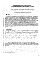
The soil support system usually consists of a base, a
sub-base and a subgrade, as illustrated in Fig. 3.1. If the
existing soil has the required strength and properties to
support the slab, the slab may be placed directly on the
existing subgrade. However, the existing grade is not
normally at the correct elevation or slope. Therefore,
some cut or fill is required with the best of site selec-
tions.
3.2-Soil classification and testing
There are many standards by which soils are clas-
sified. The Unified Soil Classification System is used in
this document. Table 3.2.1 provides information on this
classification system and some important properties of
each soil class. For complete details, see ASTM D 2487.
The nature of the soil must be identified in order to
determine its suitability as either a base, a subbase, or a
I Load
Slab
Fig. 3.
l-Soil system support terminology
subgrade
material. Various laboratory tests can be per-
formed in order to identify the soil. Soil classification is
based primarily on grain size and the Atterberg limits as
indicated in Table 3.2.2.
The following tests and test methods are helpful in
proper classification of soil:
1. Sample preparation - ASTM D 421
2. Moisture content - ASTM D 2216
3. Specific gravity
-
ASTM D 854
4. Material larger than
#4
Sieve
-
ASTM C 127
5. Liquid limits - ASTM D 4318
6. Plastic limit - ASTM D 4318
7. Shrinkage limit
-
ASTM D 427
8. Sieve analysis
-
ASTM D 422
9. Standard Proctor density
-
ASTM D 698
10. Modified Proctor density - ASTM D 1557
A more detailed listing of the ASTM standards is given
in Chapter 10.
3.3-Modulus of
subgrade
reaction
3.3.1
Introduction-Design methods listed in Chapter
2, including Westergaard’s pioneering work, use the mod-
ulus of
subgrade
reaction to account for soil properties
in design. The modulus, also called the modulus of soil
reaction, is a spring constant that depends on the kind of
soil, the degree of compaction, and the moisture content.
The general procedure for static non-repetitive plate load
tests outlined in ASTM D 1196 provides guidance in the
field determination of the
subgrade
modulus. However,
it is not specifically oriented to the determination of
modulus of
subgrade
reaction using a 30 in. diameter
plate for the test. Therefore, a brief description of the
procedure is given in Sec. 3.3.2.
3.3.2 Procedure for the field test-Remove loose ma-
terial from the surface of the grade or subgrade for an
area 3 to 4 feet in diameter. Place a thin layer of sand or
plaster of
paris
over this area to assure uniform bearing
under the load plates. Then place three 1-in thick steel
plates,
30,24,
and 18 inches in diameter, stacked concen-
trically pyramid fashion on this surface. Rotate the plates
on the bearing surface to assure complete contact with
the subgrade.
Attach a minimum of three dial gages to
18-ft
deflec-
tion beams spanning across the load plates. Position the
three dial gages on the top of the 30-in. plate, 120
degrees apart, to record the plate deflection. Generally,
a heavy piece of construction equipment can provide the
8000-lb
load required for the test. Place a hydraulic jack
on the center of the load plates and apply a proof load
of approximately 700 to 800 lb to produce a deflection of
approximately 0.01 in. Maintain this load until the settle-
ment is stabilized; then release the load and reset the
dial gages to zero.
After this preparation, the test is performed by apply-
ing a series of loads and recording the settlement of the
plates. Generally, three load increments are sufficient.
DESIGN OF
SLABS
ON GRADE
Table
3.2.1-Unified
soil classification system, from Reference 22
FIELD IDENTIFICATION PROCEDURES GROUP
(Excluding particles larger than 3 inches, and basing fractions on estimated weights)
SYMBOL TYPICAL NAMES
360R-9
Wide range in grain size and
substantial amounts of all
Well graded gravels, gravel-
GW
sand mixtures, little or no fines
CLEAN
GRAVELS
(Little or no
fines)
intermediate particle sizes
Predominantly one
size
or a Poorly graded gravels, gravel-
GRAVELS
More than half of
coarse fraction is
larger than No. 4
sieve*
range of sizes with some inter-
GP
sand mixtures, little or no fines
mediate sizes missing
Non-plastic fines (for
identifi-
Silty gravels, poorly graded
cation procedures see CL
below.)
GRAVELS WITH
FINES
(Appreciable
amount of fines)
GM
GC
SW
gravel-sand-silt mixtures
Clayey gravels, poorly graded
gravel-sand-clay mixtures
Well graded sands, gravelly
sands, little or no fines
COARSE
GRAINED
SOILS
(More than half of
material is larger
than No. 200
sieve*)
Plastic
fines
(for identification
procedures see ML below)
Wide range in grain sizes and
substantial amounts of all
SANDS
More than half of
coarse fraction is
smaller than No.
4 sieve*
CLEAN SANDS
(little or no fines)
intermediate particle sizes
Predominantly one
size
or a Poorly graded sands, gravelly
range of sizes with some in-
SP
termediate sizes missing
SANDS WITH
Non-plastic fines (for identifi-
FINES
cation procedures see ML
SM
(appreciable below)
amount of fines)
Plastic
fines
(for identification
procedures see CL below)
SC
Identification procedures on
fraction
smaller than no. 40 sieve
sands, little or no fines
Silty sands, poorly graded
sand-silt mixtures
Clayey sands, poorly graded
sand-clay mixtures
DRY
STRENGTH
(crushing
characteristics)
Quick to slow
TYPICAL NAMES
GROUP
SYMBOL
SILTS AND
CLAYS, liquid
limit less than 50
Inorganic silts and very fine
sands, rock flour, silty or clayey
fine sands with slight plasticity
None to slight
ML
FINE
GRAINED
SOILS (more than
half of material is
smaller than No.
200 sieve*)
Inorganic clays of low to medi-
um
plasticity, gravelly clays,
sandy clays, silty clays, lean
clays
Medium to high
CL
Organic
silts
and organic-silt
OL
Slight to
medium
Slight to
medium
clays of low plasticity
Inorganic silts, micaceous or
diatomaceous fine sandy or silty
soils, elastic silts
Inorganic clays of high plasticity,
MH
SILTS AND
CLAYS, liquid
limit greater
than 50
High to
very high
Medium to
high
Readily
identified by color, odor, spongy fell; frequently
by fibrous texture
fat clays
, ,
,
s texture
CH
Organic clays of medium to high
plasticity
Peat and other highly organic
OH
PT
soils
HIGHLY ORGANIC SOILS
* NOTES: All sive sizes here are US. standard. The No. 200 sieve is about the smallest particle visible to the naked eye. For visual cIassifications,the size
may be used as equivalent for the No.4 sieve size. BOUNDARY CLASSIFICATIONS: Soils possessingcharacteristicsof two groups are designated by combinations
of group symbols.
The load should be maintained until the rate of settle-
ment, an average recorded by dial gages is less than 0.001
in. per minute. The data should then be plotted on a
load deflection graph and the modulus of
subgrade
re-
action
k determined. The value of k is calculated as 10
divided by the deformation produced by a 10 psi load. (A
7070-lb
load produces 10 psi on a
30-in.
plate.) If the dial
gages are not zeroed before the test is run, an adjustment
to the curve is required to make it intersect the origin as
shown in Fig. 3.3.2. The calculation for
k is also shown.
3.3.3
Modified modulus of
subgrade
reaction-A
modified modulus of
subgrade
reaction, based on a
12-
in diameter plate test, can also be used to design slabs
on grade. The modified modulus test is less expensive to
perform, and the value for a given soil is twice that of
the standard modulus.
3.3.4
Influence of moisture content-The moisture
content of a fine-grained soil affects the modulus of
subgrade
reaction both at the time of testing and during
th.e service life of the slab. For example, if the field test
for a modulus of
subgrade
reaction is performed on a
clay stratum with a liquid limit (LL) less than 50 and a
360R-10
ACI COMMITTEE REPORT
Table
3.2.2- Laboratory classification criteria for soils
, from Reference 22
Major Divisions
Group
Symbols
Typical Names
Laboratory Classification Criteria
Well-graded
gravels,
gravel-sand mix-
greater
than
4;
-
-
between
1 and 3
tures, little of no fines
x
Poorly graded gravels, gravel-sand
mix-
turet, little or no fines
Not meeting all gradation requirements for
GW
,
Silty gravels, gravel-sand-silt mixtures
Clayey
gravels, gravel-sand-clay
mix-
tures
Atterberg limits below
Above "A" line with P.I.
"A" line or
P.I. less than 4
between
4 and
7 are border-
’
line cases requiring use Of
Atterberg limits
below
“A” dual symbols
line
with
P.I. greater than 7
Well-graded sands, gravelly sands, little
or no fines
=
-
greater than 6;
=
-
between
1
and 3
x
Poorly graded sands, gravelly sands,
Not meeting all gradation requirements for S W
little or no fines
“0%
Silty sands, sand-silt mixtures
Atterberg
limits
above “A”
line or
P.I.
less than 4
Limits plotting in hatched
zone with P.I. between 4
SC
Clayey sands, sand-clay mixtures
Atterberg
Atterberg limits
above
“A”
and 7 are borderline cases
line with P.I. greater than 7
requiring
use of dual sym-
bols
Inorganic silts and very fine sands,
ML
rock flour, silty or clayey fine sands,
or clayey silts with slight plasticity
Plasticity Chart
Inorganic clays of low to medium
8
60
CL
plasticity, gravelly clays, sandy clays,
silty clays, lean clays
.
.
OL
Organic silts and organic silty clays of
50
low plasticity
40
Inorganic silts, micaceous or
diatoma-
30
MH
ceous
fine sandy or silty soils, elastic
silts
ii;;;
CH
Inorganic clays of high plasticity, fat
20
clays
c
OH
Organic clays of medium to high
1O
Pt
plasticity, organic silts
Peat and other highly organic soils
Liquid limit
of GM and SM groups into subdivisions of d and u
are for roads and airfields only. Subdivision is based on Atterberg limits; suffix d used when
L.L. is 28 or less and the P.I. is 6 or less; the suffix u used when L.L.is greater than 28.
example:
GW-GC, well-graded gravel-sand mixture with clay binder.
DESIGN OF
SLABS
ON GRADE
360R-11
DEFORMATION IN INCHES
0
0.02
0.04 0.06 0.08
0.10
STANDARD MODULUS OF SOIL REACTION K
180
LBS./CU.IN.
.
Fig. 3.3.2-Load-deformation plot for the plate field test
moisture content of 15 percent, the value of k will be
higher than if the same test is performed with the
material at a 23 percent moisture content.
Table 3.3.4 shows the approximate effect of moisture
content on the value of the modulus of
subgrade
reaction
for various types of soil. The following example shows
how to the use Table 3.3.4.
Assume that a test for the modulus
k is performed
on a clay stratum (LL less than
50)
when the mois-
ture content is 23 percent. From the data
k is calcu-
lated to be 300 lb per cu in. (pci). What should the
design value be if the long term value of the moisture
content of the soil under the slab reduces to 15 per-
cent? Using correction factors in Table 3.3.4
3.3.5 Influence of soil material on modulus of
subgrade
reaction
-Fig. 3.3.5 shows the general relationship be-
tween the soil classification and the range of values for
the modulus of
subgrade
reaction. The figure also shows
a general relationship between the California bearing
ratio (CBR), modified modulus of subgrade reaction, and
standard modulus of
subgrade
reaction which is the basis
for slab on grade design.
The design examples in the appendix show the in-
fluence that the modulus of
subgrade
reaction has on the
required slab thickness. Obvious design options are to
improve the soil through such approaches as additional
compaction, chemical stabilization or site drainage.
Under actual job conditions, the soil profile is
generally made up of many layers of different materials,
with the influence of the base and subbase predominant.
k(design) =
0.65
= 392 lb per cu in.
Engineering judgement is required to select approximate
values used during design. During construction verify the
Conversely, if the moisture content at the time of the
chosen value by on site testing before placing slabs.
test is 15 percent and the projected moisture content
during the life of the slab is 23 percent, the
adjust-
3.4-Design of the slab support system
ment the test value would be:
3.4.1 General-After the soils have been classified,
the general range of
k values can be approximated from
Table 3.3.5. With this information, a decision can be
k(design) =
0.65
300
x
= 230 lb per cu in.
made to densify the soil, improve the base material with
.
Table
3.3.4-Moisture content correction factors, from Reference 22
TYPE OF MATERIAL
Silts and clays
LL
<
50
Silts and
clays
LL
>
50
Clayey sand or
Clayey gravel
5-10
0.35
0.25
0.75
Moisture content at time of test, percent of dry weight
11-14 15-18
19-21
22-24 25-28
over 28
0.50
0.65
0.75
0.85 1.0
1.0
0.35
0.50
0.63
0.75
0.85 1.0
0.9
1.0
1.0
1.0
1.0
1.0
360R-12
ACI COMMITTEE REPORT
Fig. 3.3.5-Interrelationaship of soil classification and strengths (from Reference 23)
2
3
4
56
7 8 910
15
20
25 30
40
50 60 70 80 90
I
(BCS
314)
CALIFORNIA
BEARING RATIO
"CBR",
PERCENT
I
I
I
50
l00
200
T
I
150
400 600
700
(BCS
315)
MODIFIED MODULUS OF
SOIL
REACTION
I
LBS.
/
(12’
DIAM
STANDARD MODULUS of SOIL
REACTION
(30"
DIAM.
PLATE)
G-GRAVEL
S-SAND
M-SILT
C - CLAY
W
-
WELL
GRADED
P
-
POORLY GRADED
U
-
UNIFORMLY GRADED
L
-
LOW TO MEDIUM COMPRESSIBILTY
H
-
HIGH
COMPRESSlBlLITY
0
-
ORGANIC
I
LEGEND
COMPACTED DENSITIES
,
Note: Comparison of soil type to 'K', particularly in the "L
l
Hm Groups,
should
generally be made in the lower range of the
soil type.
sand or gravel fill, or use the existing material in its
in-
situ condition.
Normally there is a wide range of soils across the
site. The soil support system is rarely uniform. Therefore,
some soil work is generally required to provide a more
uniform surface to support
the slab. The extent of this
work, such as the degree of compaction or the addition
of a sand-gravel base, is generally a problem of econom-
ics. Selection of soils in the wellgraded gravel (GW) and
poorly graded gravel (GP) groups as a base material may
appear costly. However, the selection of these materials
has distinct advantages. Not only do they provide a su-
perior modulus of
subgrade
reaction, but they also tend
to speed construction during inclement weather.
3.4.2
Economics and simplified
design-Certainly not
all projects will require all of the data discussed above.
On projects where the slab performance is not critical,
engineering judgement should be exercised to reduce
costs. A prime prerequisite for the proper design of a
slab support system is soils identification. Without this
knowledge, the modulus of
subgrade
reaction is unknown
and potential volume change cannot be determined. With
knowledge of soil classification, the engineer can select
an appropriate
k value and design for the specific soil
conditions.
For small projects, it may be advantageous to assume
a low
k factor and add a selected thickness of crushed
stone to enhance the safety factor rather than performing
an expensive soil analysis. Use of the modified modulus
of
subgrade
reaction test rather than the standard modu-
lus test can also reduce costs. Risk of slab failure at an
earlier age increases as the design is rationalized but
there are occasions where the simplified design approach
is justified. These decisions are a matter of engineering
judgment and economics.
Compounding safety factors is a common error. In-
clusion of safety factors in the modulus of
subgrade
re-
action, the applied loads, the compressive strength of the
concrete, the
flexural
strength of the concrete and the
number of load repetitions will produce an expensive
design. The safety factor is normally contained in the
flexural
strength of the concrete and is a function of the
number of load repetitions (see Sec. 4.9).
3.5-Site
preparation
3.5.1
Introduction
-Prior to soil compaction, the top
DESIGN OF SLABS ON GRADE
360R-13
6
7
Thickness of subbase, in.
Fig.
3.5.3-Effect
of selected
fill
on modulus of
subgrade
reaction (from Reference 14)
layer of soil must be stripped of all humus and frozen
material. Both hard and soft pockets of soil material
should be removed and recompacted to provide a uni-
form support for the base, subbase or concrete slab. See
ACI
302.1R
for additional information.
When a thick combination of base and subbase is
provided, sinks, holes, expansive soils, highly com-
pressible materials, or any other problems that can
influence the life of the slab must be examined. Nor-
mally, the surface is stripped and recompacted before the
subbase is placed.
3.5.2
Subgrade
stabilization
-There are many methods
of improving the performance of the soil system by
den-
sification and drainage (see list in the U.S. Navy’s Design
Generally, for slab on grade, the soil is
den-
sified by using rolling equipment such as sheepsfoot, rub-
ber tire, or vibratory rollers. The degree of compaction
is normally measured and controlled by ASTM D 698
(standard) or D 1557 (modified) Proctor density curves.
Another
densification
method used to improve the
entire building site is preloading. A surcharge is placed
over the building site in order to decrease the voids in
the original soil system. This procedure not only reduces
total and differential settlement for the overall structure
but also improves the modulus of
subgrade
reaction.
Drainage of the soil is an effective approach to
den-
sification. The site is drained by ditches, tunnels, pervious
fills, or subsoil drains. This reduces ground water pres-
sure and increases effective stresses in the soil system.
Chemical methods listed in Table
3.5.2
can also be
used to stabilize soil. Generally, portland cement, lime,
calcium chloride, or bitumen is mixed into the soil sub-
strata, and the mixture is recompacted. Less common
than densification stabilization, chemical stabilization is
a viable procedure, especially with expansive soils.
3.5.3 Base and subbase
material-
The
base and sub-
base frequently comprise a thick stratum used to bring
the surface of the soil support system to a uniform ele-
vation under the slab. The subbase is usually a good eco-
nomical fill material, with the base being a thinner layer
of more expensive material having a superior value of
modulus of
subgrade
reaction.
Often the existing subgrade may be a satisfactory
base material. Generally the materials listed in Fig. 3.3.5
that yield a standard modulus of subgrade reaction above
125 pci, can be used. The soils below this value, as well
as the low compressibility organic material (OL) and high
compressibility silt (MH) are to be avoided. Note in Fig.
3.3.5 that
k for soil type CL (low compressibility clay)
ranges from 70 to a high of 250. Much of this variation
is a product of the degree of compaction and/or moisture
content of the soil.
Frequently, a selected fill
used as a
base
bears on a weaker subgrade.
Normally,
these
material
selected
materials are from the G and S (gravel and sand) classi-
fication. How they affect
k values depends on both the
type and thickness of the material. A typical effect of
selected fill on kvalues is shown in Figure 3.5.3. Data for
specific designs should be based on laboratory analysis
and site testing.
3.5.4 Stabilization of base and subbase-Weak base
material can be stabilized by the addition of chemicals
that are mixed or combined with the soil, as shown in
Table 3.5.2. Lime and calcium are also used to lower the
plasticity index of subgrades, subbases, and base mater-
ials. For silty soils, portland cement may be effective. It
is recommended that a geotechnical expert plan, super-
vise, and analyze the soil conditions before chemical sta-
bilization is used.
Base and subbase material are often densified by
mechanical compaction with a subsequent improvement
in the
k value. The relative cost of options such as
chemical stabilization or providing a thicker slab should
be considered.
The mechanical compaction of clay and silt is meas-
ured as a percent
of standard Proctor density
(ASTM D 698) or modified Proctor density
(ASTM D 1557). Nominal targets for these materials are
from 90 to 95 percent of the modified Proctor density.
Estimates of
k values resulting from this and other
com-
pactive
efforts can be projected from laboratory CBR
values, as shown in Fig. 3.3.5. The depth of compacted
lifts varies with soil type and compaction equipment, but
in most cases should be 6 to 9 inches (150-225 mm).
Granular soils are most responsive to vibratory equip-
ment and cohesive soils respond best to sheepsfoot and
rubber-tired rollers.
3.5.5
Grading
tolerance-
Initial rough grade tolerance
should be
0.1 ft (30 mm). After the forms are set, final
grading and compaction should be completed prior to
slab placement. The final elevation of the
should be no more than
in. above or
design grade.
base material
in. below the
360R-14
ACI COMMITTEE REPORT
Table
3.5.2-Soil
stabilization with chemical admixtures
ADMIXTURE
QUANTITY, % BY
PROCESS
APPLICABILITY
EFFECT ON SOIL
WEIGHT OF
STA-
PROPERTIES
BILIZED SOIL
PORTLAND
CEMENT
Varies from about
to
4% for cement treatment
to 6 to 12% for soil ce-
ments
BITUMEN
3 to 5% bitumen in the
form of cutback asphalt
emulsion, or liquid tars
for sandy soils. 6 to 8%
asphalt emulsions and
light tars fir fine grain
materials. For coarse
grain soils antistrip
compounds are added
to promote particle
coating by bitumen.
CALCIUM
TO 1
CHLORIDE
LIME
4 to 8%.
Flyas
h, betwe-
en 10 and
20%,
may be
added to increase
pozz-
olanic action.
Cohesive soil is pulverized so
that at least 80% will pass
No. 4 sieve, mixed with ce-
ment, moistened to between
optimum and 2% wet, com-
pacted to at least 95% maxi-
mum density and cured for 7
or 8 days while moistened
with light sprinkling or pro-
tected by surface cover
Forms stabilized subgrade or
base course. Wearing sur-
face should be added to
provide abrasion resistance.
Not applicable to plastic
clays.
Unconfined compressive
strength increased up to
about 1000 psi. Decreases
soil plasticity. Increases dura-
bility in freezing and thawing
but remains vulnerable to
frost.
Soil is pulverized, mixed with
bitumen, solvent is aerated
and mixture compacted. Be-
fore mixing, coarse
grained
soils should have moisture
content as low as 2 to 4%.
Water content of fine
grained
soils should be several per-
cent below optimum.
Normally applied at rate of
about 0.5
Ib/sq
yd area. Dry
chemical is blended with
soil-
aggregate mixture, water
added, and mixture compact-
ed at optimum moisture by
conventional compaction
procedures.
Forms wearing surface for
construction stage, for em-
ergency conditions or for low
cost roads. Used to form
working base in cohesionless
sand subgrades, or for im-
proving quality of base
course. Not applicable to
plastic clays.
Used as dust palliative. Sta-
bilized mix of gravel-soil
binder calcium chloride
forms wearing surface in
-
some secondary roads.
Lime is spread dry, mixed
with soil by pulvi-mixers or
discs, moisture compacted at
optimum moisture to ordinary
compaction densities.
Used for base course and
subbase stabilization. Gener-
ally restricted to warm or
moderate climates because
the mixture is susceptible to
breakup under freezing and
thawing.
3.6-Inspection and site testing of soil support
To control the quality of the soils work, inspection
and testing are required. As the soil support system is
placed, the soil classification of the fill material should
already have been determined and the in-place density
should be checked. The in-place density as a percent of
standard or modified Proctor density should be verified
using a nuclear density meter (ASTM D 2922) or by the
sand cone method (ASTM D 1556).
After the controlled fill is placed, the surface of the
base should be checked for in-situ
k values. Higher
in-
situ
k
values offer an opportunity for thinner slabs. Low-
er values require a thicker slab or indicate a lower effec-
tive factor of safety with a decrease in slab life.
Testing frequency is related to the work quality. Sub-
standard work may require more testing. The over-all
quality of the work can be controlled by statistical analy-
sis similar to that used in Sections 2.3.1 and 2.3.2 of
ACI
318 to maintain quality control of the concrete. A rea-
sonable target is to be 90 percent certain that 85 percent
of the work meets or exceeds minimum specifications.
Fig. 3.6 can be used to evaluate achievement of this tar-
get
For example, if the minimum specified modified
Proctor density is 90 percent, and the first six tests fur-
nished by the soils technician are as follows: 93, 92, 94,
93, 88 and 95 percent; then the average of these values
is 92.5 percent. The spread is from 88 percent to 95 per-
cent, or 7 percent. When this spread is plotted on Fig.
3.6 (point A), it falls below the line for six tests, and fails.
Therefore, one cannot be 90 percent certain that 85 per-
cent of the compaction work will meet the specified mini-
mum. If six tests yield values of 91, 95, 95, 96, 93 and 95
percent modified Proctor, then the average is 94.1 per-
cent and the spread is 5 percent. When this is plotted on
Fig. 3.6 (point B) it is above the control line for six tests,
and therefore the compaction meets the target.
Provides a binder to improve
strength and to waterproof
stabilized mixture.
Retards rate of moisture eva-
poration from the stabilized
mixture, tends to reduce soil
plasticity. Greatest effect in
sodium clays with capacity
for base exchange. Lowers
freezing point of soil water,
decreasing loss in strength
from freezing and thawing.
Decreases plasticity of soil,
producing a grainy structure.
Greatest effect in sodium
clays with capacity for base
exchange. Increases com-
pressive strength up to a
maximum of about 500 psi.
DESIGN OF SLABS ON GRADE
PLOTS ABOVE THE CONTROL
LINE ASSURE THAT
85%
OF
THE WORK MEETS “MINIMUM
ACCEPTABLE”.
360R-15
IF
A PLOT BELOW THE
CONTROL
WE CANNOT TELL
WHETHER OR
THE WORK
MEETS
ACCEPTABLE.”
DO SOMETHING ELSE.
.
.
.
.
.
.
.
.
MAXIMUM SPREAD BETWEEN TESTS
NOTE: ONE INCH ON BOTH THE HORIZONTAL AND VERTICAL SCALES MUST EQUAL THE SAME NUMBER OF UNITS.
CONFIDENCE LEVEL
=
90%
Fig.
3.6-Evaluation
of control test results for soil compaction
3.7-Special slab on grade support problems
under freezer areas, and under ice skating rink floors.
26
Placement of slabs on topsoil should generally be
avoided. In extreme cases where it is unavoidable, spe-
cial precautions and approaches must be undertaken, as
described in Reference 25.
CHAPTER 4-LOADS
Expansive soils are defined as fine grained soils, as
shown in Tables 3.2.1 and 3.2.2. As a general rule, any
soil with a plasticity index of 20 or higher has a potential
for significant volume change. A geotechnical engineer
4.1-Introduction
should examine the soil data
options. Potential problems
and
can
recommend appropriate
be minimized by proper
This chapter describes loadings and load conditions
commonly applied to concrete slabs on grade. Appropri-
ate factors of safety and the variables that control load
effects are described. Where vertical forces from a super-
structure are transmitted through the slab on grade to
the soil, requirements of the applicable building code
must also be followed.
slab designs, stabilization of the soil, or by preventing
moisture migration under the slabs. Failure to manage
the problem can and often will result in early slab failure.
Frost action may be critical to silts, clays, and some
sands. These soils can experience large changes of vol-
ume when subjected to freezing cycles. Three conditions
must be present for this problem to occur:
l
Freezing temperature in the soil
l Water table close enough to the frost level to
form ice lenses
l
A soil that will act as a wick to transmit water
from the water table into the frost zone by cap-
illary action
Possible remedies include lowering the water table, pro-
viding a barrier, or using a subbase/subgrade soil that is
not frost susceptible. Properly designed insulation can be
beneficial. Volume changes occur at building perimeters,
Concrete slabs are usually subjected to some com-
bination of the following:
l Vehicle wheel loads
l Concentrated loads
l Line and strip loads
l Uniform loads
Construction loads
l
Environmental effects including expansive soil
l
Unusual loads, such as forces caused by differ-
ential settlement
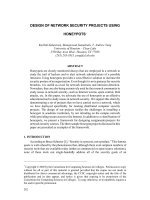
Slabs must be designed for the most critical combination
of these loading conditions, considering such variables as
the maximum load, its contact area, and load spacing.
The Portland Cement Association guide for selecting the
most critical or controlling design considerations for
var-
360R-16
ACI COMMITTEE REPORT
TYPE OF
LOAD
I
CONCENTRATED LOADS
DISTRIBUTED LOADS
POSTS OF
STORAGE
RACK
WITHOUT
WITH
BASE PLATES
VEHICLE WHEELS
0
STORAGE
SOLID PNEUMATIC SPECIAL
TIRES
TIRES TIRES
I
e.g.
-
rol I8 or coils
3 to7-ft.dia.
-
FLEXURAL
STRESS UNDER LOAD
I I I I I I I
I I
2
4
IO
20 40 200 400
20 40 200 400
SQUARE INCHES
SQUARE FEET
LOAD CONTACT AREA
(for each tire, post, or single loaded area)
Fig.
4.1-Controlling
design considerations for various types of slab on grade loadings (from Reference 14)
ious load is presented in Fig. 4.1. Since a number
of factors such as slab thickness, concrete strength,
sub-
grade stiffness, compressibility, and loadings are relevant,
areas where several design considerations may control
should be investigated thoroughly.
Other potential problems such as load conditions
which change during the life of the structure and those
encountered
ered. For exa
during
must also be
consid-
mple, material handling systems today make
improved use of the building volume. Stacked pallets
which were once considered uniform loads may now be
stored in narrow-aisle pallet racks which produce con-
centrated loads. Critical loading conditions may change,
and load magnitudes may increase due to the storage of
denser materials or the use of new handling
In either case, the actual loading during the life of the
structure and its grade slab may differ significantly from
the original design assumptions.
The environmental exposure of the slab on grade is
also a concern. Normally, thermal effects are not con-
sidered since the slab is usually constructed after the
building is enclosed. However, with the use of strip place-
ment, more and more slabs are being placed prior to
building enclosure. The construction sequence is there-
fore important in determining whether or not environ-
mental factors should be considered in the design. This
is discussed in greater detail in Chapter 9.
4.2-Vehicle loads
Most vehicular traffic on industrial floors consists of
lift trucks and distribution trucks with payload capacities
as high as 70,000 lb. The payload and much of a truck’s
weight are generally carried by the wheels of the loaded
axle. The Industrial Truck
has compiled re-
presentative load and geometry data for lift truck
capa-
cities up to 20,000 lb (Table 4.2). The contact area be-
tween tire and slab must also be included in the analysis
for larger lift trucks with pneumatic or composition
Vehicle variables affecting the thickness selection and
design of slab on grade include the following:
l Maximum axle load
l
Distance between loaded wheels
l Tire contact area
Load repetitions during service life
The axle load, wheel spacing, and contact area are a
function of the lift truck or vehicle specifications. If
vehicle details are unknown, the values in Table 4.2 may
be adopted. The number of load repetitions, which may
be used to help establish a factor of safety, is a function
of the facility’s usage. Knowledge of load repetitions
helps the designer to quantify fatigue. Whether these val-
ues are predictable or constant during the service life of
a slab must also be considered.
The contact area of a single tire can
be
approxi-
mated by dividing the tire load by the tire
DESIGN OF SLABS ON GRADE
360R-17
This is somewhat conservative since the effect of tension
The concentrated load variables which affect design
in the tire wall is not included. Assumed pressures are
of the slab on grade are:
variable; however, pneumatic tire pressures range from
l
Maximum or representative post load
80 to 100 psi, while steel cord tire pressures range up to
l
Spacings between posts and aisle width
120 psi. The Industrial Truck Association found that the
l
Area of contact between post or post plate and
standard solid and cushion solid rubber tires have floor
slab
contact areas that may be based on internal pressures
be-
tween 180 and 250
Material handling systems are a major part of the
build-
ing layout and are generally well-defined early in the
pro-
Dual tires spread the load over an area greater than
ject. Rack data can be obtained from the manufacturer.
the actual contact area of the two individual tires. An
It is not uncommon to specify a larger base plate than is
area equal to that of the two tires and the area between
them is a conservative
The rectangular area
normally supplied to reduce the stress effect of the
con-
centrated load.
between the tires has a length equal to the distance be-
tween tires and a width equal to the diameter of the
4.4-Uniform loads
single tire contact area. If it is not known whether the
In many warehouse and industrial-buildings, materials
vehicle will have dual wheels or what the wheel spacings
are stored directly on the slab on grade. The
flexural
are, then a single equivalent wheel load and contact area
stresses in the slab are usually less than those produced
can be used conservatively.
by concentrated loads. The design must endeavor to pre-
vent negative moment cracks in the aisles and to prevent
4.3-Concentrated loads
excessive settlement. The effect of a lift-truck operating
Because of increasing building costs, there has been
in the aisles between uniformly loaded areas is not
nor-
a trend toward more efficient use of warehouse space.
mally combined with the uniform load into one loading
This has led to narrower aisles, higher material stacking,
case, as the moments produced generally offset one
an-
and the use of automated stacking equipment. Material
other. However, the individual cases are always
consid-
storage racks may be higher than 80 ft and may produce
ered in the design.
concentrated post loads of 40,000 lb or more. For the
For uniform loads, the variables affecting the design
higher racks, these loads may well exceed the vehicle
of slab on grade are:
wheel loads and thus control the thickness selection.
l Maximum load intensity
l
Width and length of loaded area
Table
4.2-Representative
axle loads and wheel spacings
l Aisle width
for various lift truck capacities (from Reference 27)
l
Presence of a joint located in and parallel to the
Truck rated
Total
axle load
capacity, lb
static
reaction,
2,000
5,600-7,200 24-32
3,000
7,800-9,400
26-34
4,000
9,800-11,600 30-36
5,000
11,600-13,800
30-36
6,000
13,600-15,500
30-36
7,000
15,300-18,100
34-37
8,000
16,700-20,400
34-38
10,000
20,200-23,800
37-45
12,000
23,800-27,500
38-40
15,000
30,000-35,300
34-43
20,000
39,700-43,700
36-53
lb
Center to center
of opposite wheel
tires, in.
The concentrated reaction per tire is calculated by dividing the total axle load re-
action by the number of tires on that axle. Figures given are for standard trucks.
The application of attachments, extended high lifts, etc., may increase these val-
ues. In such case, the manufacturer should be consulted. Weights given are for
trucks handling the rated loads at 24 in. from load center to face of fork with
mast vertical.
In some designs where these racks also support the
building’s roof the rack posts themselves are primary
structural elements. Appropriate requirements of the
building code, including mandatory safety or load factors,
must be followed.
aisle
Loads for randomly stacked materials are not normally
predictable, nor are they constant during the service life
of a slab. Therefore, the slab should be designed for the
most critical case. The maximum moment in the center
of an aisle is a function of aisle width as well as other
parameters. For a given modulus of
subgrade
reaction,
modulus of rupture, and slab thickness, there is an aisle
width that maximizes the center aisle moment. This criti-
cal
are
aisle width is
generally less
important in the design. Wider aisles
critical.
4.5-Line
and strip loads
A line or strip load is a uniform load distributed over
a relatively narrow area. A load may be considered to be
a line or strip load if its width is less than one-third of
the radius of relative stiffness (see Sec. 2.4.2). When the
width approximates this limit, the slab should be review-
ed for stresses produced by line loading as well as uni-
form load. If the results are within 15 percent of one an-
other, the load should be taken as uniform. Partition
loads, bearing walls, and roll storage are examples of this
load type.
The variables for line and strip loads are similar
to
those for uniform loadings and include:
Maximum load intensity
l
Width and length of loaded area
ACI COMMITTEE REPORT
360R-18
100
9
a
.
8
a
7
8
Wheel
Load, Kips
Fig. 4.7-Tire contact area for various wheel loads
l Aisle width
l
Presence of a joint in and parallel to the aisle
l
Presence of parallel joints on each side of the
4.6-Unusual
loads
Loading conditions that do not conform to the previ-
ously discussed load types may also occur. They may dif-
fer in the following manner:
a) Configuration of loaded area,
b) Load distributed to more than one axle,
c)
More than two or four wheels per axle.
However, the load variables and the factor of safety will
be similar to those for the load types previously discussed
in this chapter.
4.7-Construction loads
During the construction of a building, various types
of equipment may be located on the newly-placed slab on
grade. The most common construction loads are pick-up
trucks, concrete trucks, dump trucks, and hoisting equip-
ment. In addition, the slab may be subjected to other
loads such as scaffolding and material pallets. Some of
these loads can exceed the functional design limits, and
their effects should be anticipated.
The controlling load variables for construction loads
are the same as for vehicle loads, concentrated loads, and
uniform loads.
For construction trucks, the maximum axle load and
other variables can usually be determined by reference to
local transportation laws or to the American Association
of State Highway and Transportation Officials standards.
Off-road construction equipment may exceed these limits,
but in most cases, construction equipment will not exceed
the legal limits of the state. Fig. 4.7 gives values of con-
tact area for wheel loads that can be used for design.
4.8-Environmental
factors
Stresses and load effects produced by thermal and
moisture changes must be considered in the overall
de-
1
3
5
8
Wheel
Load,
Kips
sign. These effects are of particular importance for ex-
terior slabs and for slabs constructed before the building
is enclosed. Curling caused by these changes increases
the
flexural
stress due to the reduction in
subgrade
sup-
port. Generally, the restraint stresses can be ignored in
short slabs, since the
subgrade
does not significantly re-
strain the short-slab movement due to uniform thermal
expansion, contraction, or drying shrinkage. Built-in re-
straints, such as foundation elements, edge walls, and pits
should be avoided. Environmental factors are discussed
further in Chapter 9.
4.9-Factors
of safety
The factor of safety for a slab on grade is never dic-
tated by a building code. The designer selects it on the
basis of
The safety factor accounts for a
number of items including:
l
Ratio of modulus of rupture to the tensile bend-
ing stress caused by imposed loadings
l
Influence of shrinkage stresses
l
Number of load repetitions
l Fatigue and impact effects
A critical factor in the performance of a slab is the num-
ber of vehicles crossing a slab edge or joint. Shrinkage
stresses and impact are usually less significant in the
design, but shrinkage is important to performance since
it causes cracking, curling, dishing, and subsequent
strength loss. Shrinkage stresses and the relationship of
subgrade drag and joint spacing are discussed in Chapters
6 and 9.
A moving vehicle subjects the slab on grade to the ef-
fect of fatigue. Fatigue strength is expressed as the per-
centage of the static tensile strength that can be
support-
ed for a given number of load repetitions. As the ratio of
the actual
flexural
stress to the modulus of rupture de-
creases, the slab can withstand more load repetitions be-
fore failure. For stress ratios less than 0.50, concrete can
be: subjected to unlimited load repetitions according to
Table 4.9.1 (taken in part from Reference 8)
shows various load repetitions for a range of stress ratios.
DESIGN OF SLABS ON GRADE
360R-19
The safety factor is the inverse of the stress ratio.
Commmonly applied safety factors are shown in
Table 4.9.2 for the various types of slab loadings. Most
range from 1.7 to 2.0, although factors as low as 1.4 are
applied for some conditions. For more substantial con-
centrated structural loads, Reference 30 recommends
safety factors ranging as high as 3.9 to 4.8. These higher
Table
4.9.1-Allowable
load repetitions for various stress
ratios (from Reference 52)
Stress
Ratio
0.51
0.52
0.53
0.54
0.55
0.56
0.57
0.58
0.59
0.60
0.61
0.62
0.63
0.64
0.65
0.66
0.67
0.68
400,000
300,000
240,000
180,000
130,000
100,000
75,000
57,000
42,000
32,000
24,000
18,000
14,000
11,000
8,000
6,000
4,500
3,500
0.69
0.70
0.71
0.72
0.73
0.74
0.75
0.76
0.77
0.78
0.79
0.80
0.81
0.82
0.83
0.84
0.85
Table
4.9.2-Factors
of safety used in
design for various types of loading
Moving wheel
loads
1.7 to 2.0 1.4 to 2.0+
5.2-Portland
Cement Association (PCA) design method
Concentrated
(rack and post
loads
1.7 to 2.0
Higher under
special
circumstances
Uniform loads
1.7 to 2.0
1.4
Line and strip
loads
1.7
2.0 is a
conservative
upper limit*
Construction
loads
1.4 to 2.0
Commonly Used Occasionally
Factors of
Used factors
Safety
of Safety
Allowable
Repetitions
2,500
2,000
1,500
1,100
850
650
490
350
270
210
160
120
90
70
50
40
30
is lower
limit
* When a line load is considered to be a structural load due to building function,
appropriate building code requirements must be followed.
values are for special circumstances where the slab is
5.2.2
Concentrated
loads-Concentrated loads can be
considered to be governed by requirements for plain con-
more severe than wheel loads. Generally flexure controls
crete. Higher values may also be applicable where settle-
the concrete slab thickness. Bearing stresses and shear
ment controls or where rack layouts
are not coordinated
with the area layout.
4.10-Summary
Externally-applied loads and environmental factors
that affect the design of slabs on grade are not as clearly
defined as they are for structural elements subjected to
usual building loads. However, since slab
distress is
caused by external loadings as well as environmental ef-
fects, it is important to account for these factors ac-
curately.
CHAPTER 5-DESIGN OF PLAIN
CONCRETE SLABS
5.1-Introduction
Slabs on grade are frequently designed as plain con-
crete slabs where reinforcement, if used in any form,
serves in a manner other than providing strength to the
uncracked slab. The amounts of reinforcement used, as
well as joint spacings, are to control cracking and to
prevent the cracks from gaping or
The purpose of the plain concrete slab on grade is to
transmit loadings from their source to the
subgrade
with
minimal distress. Design methods cited consider the
strength of the concrete slab based on its
uncracked
and
unreinforced properties.
Three methods available for selecting the thickness of
the plain slab on grade are described in this chapter:
l
The Portland Cement Association (PCA) method
l
The Wire Reinforcement Institute (WRI) method
l
The Corps of Engineers (COE) method
The PCA and WRI methods are for interior loadings
while the COE method is for edge or joint loading cases
only. Design examples in Appendices Al, A2, and A3
show how to use all three methods.
The
PCA method is based on Pickett’s analysis?’ The
variables used are
flexural
strength, working stress, wheel
contact area and spacing, and the
subgrade
modulus. As-
sumed values are Poisson’s ratio (0.15) and the concrete
modulus of elasticity (4000 ksi). The PCA Method is for
interior loadings only; that is, loadings are on the surface
of the slab but are not adjacent to free edges.
5.2.1 Wheel loads-Grade slabs are subjected to var-
ious types, sizes, and magnitudes of wheel loads.
Lift-
truck loading is a common example, where forces from
wheels are transmitted to the slab. Small wheels have tire
inflation pressures in the general range of 85
to 100 psi
for pneumatic tires, 90 to 120 psi for steel cord tires, and
150 to
250
psi for solid or cushion tires. Large wheels
have tire pressures ranging from
50
to 90 psi. Appendix
Al shows use of the PCA design charts for wheel load-
ings.
stresses at the bearing plates should also be checked. De-
sign for concentrated loads is the same as for wheel
loads. Appendix Sec. Al.3 shows the PCA design charts
used for concentrated loads as found in conventionally
spaced rack and post storage.
5.2.3
Uniform loads-Uniform loads do not stress the
concrete slab as highly as concentrated loads. The two
main design objectives are to prevent top cracks in the
unloaded aisles and to avoid excessive settlement due to
consolidation of the subgrade. The top cracks are caused
by tension in the top of the slab and depend largely on
slab thickness and load placement. Consolidation of the
subgrade
is beyond the scope of this report. The PCA
tables for uniform loads (Appendix Al) are based on the
work of
considering the
flexural
strength of
the concrete and the
subgrade
modulus as the main vari-
ables. Values other than the
flexural
strength and
sub-
grade modulus are assumed in the tables.
5.2.4
Construction loads-The PCA method does not
directly address construction loading. However, if such
loading can be determined as equivalent wheel loads,
concentrated loads or uniform loads, the same charts and
tables can be used.
5.3-Wire
Reinforcement Institute
(WRI)
design method
5.3.1 Introduction-
The WRI design charts, for in-
terior loadings only, are based on a discrete element
computer model. The slab is represented by rigid bars,
torsion bars for plate twisting, and elastic joints for plate
bending. Variables are slab stiffness factors (modulus of
elasticity,
subgrade
modulus, and trial slab thickness),
diameter of equivalent loaded area, distance between
wheels,
flexural
strength, and working stress.
5.3.2
Wheel loads-Grade slabs subjected to wheel
loadings were discussed in Section
5.2.1.
The WRI thick-
ness selection method starts with an assumption of slab
thickness so that the stiffness of slab relative to the
subgrade
is determined. The moment in the slab caused
by the wheel loads and the slab’s required thickness are
then determined. Appendix A2 shows the use of the
WRI design charts for wheel loadings.
5.3.3
Concentrated loads-WRI charts do not cover
concentrated loads directly. It is possible, however, to
determine the equivalent wheel loading which represents
a concentrated loading and thereby use the wheel load
charts for this purpose.
5.3.4
Uniform
loads-
WRI
provides other charts (Ap-
pendix A2) for design of slab thickness where the loading
is uniformly distributed on either side of an aisle. In ad-
dition to the variables listed in Section
5.3.1,
the width of
the aisle and the magnitude of the uniform load are vari-
ables in this method.
5.3.5
Construction loads-Various construction loads
such as equipment, cranes, ready-mix trucks, and pick-up
trucks may affect slab thickness design. As with the PCA
design method, these are not directly addressed by WRI.
However, thickness design may be based on an equiva-
lent loading expressed in terms of wheel loads or uniform
5.4-Corps
of Engineeers (COE) design method
The COE design charts are intended for wheel and
axle loadings applied at an edge or joint only. The
vari-
ables inherent in the axle configuration are built into the
design index category. Concentrated loads, uniform loads,
construction loads, and line and strip loads are not
covered.
loads.
The COE method is based on Westergaard’s formula
for edge stresses in a concrete slab on grade. The edge
effect is reduced by a joint transfer coefficient of 0.75 to
account
for load transfer across the joint. Variables are
concrete
flexural
strength, subgrade modulus and the de-
sign index category.
The design index is used to simplify and standardize
design for the lighter weight lift trucks, generally having
less than a
25,000-lb
axle load. The traffic volumes and
daily operations of various sizes of lift truck for each
design index are considered representative of normal
warehouse activity and are built into the design method.
Assumed values are an impact factor of 25 percent,
con-
crete
modulus of elasticity of 4000 ksi, Poisson’s ratio of
0.20, the contact area of each wheel, and the wheel spac-
ings. The latter two are fixed internally for each index
category.
Appendix A3 illustrates the use of the design index
category and the COE charts. Additional design charts
(for pavements with unprotected corners and with pro-
tected corners) have been developed by the Corps of En-
gineers for pavements although they may be applied to
slabs on grade in general.
CHAPTER
6-DESIGN
OF SLABS
WITH SHRINKAGE AND
TEMPERATURE REINFORCEMENT
6.l-Introduction
Slabs on grade are designed and their thickness is se-
lected to prevent cracking due to external loading as dis-
cussed in Chapter 4. Slab thickness calculations are based
on the assumption of an
uncracked
and unreinforced
slab. Steel reinforcement-commonly plain or deformed
welded wire fabric, bar mats, or deformed reinforcing
bars-is sometimes used in slabs on grade to improve
performance of the slab under certain conditions.
Even though the slab is intended to remain
un-
cracked under service loading, the reinforcement is used
to aid in crack control; to permit use of longer joint
spacings, thereby reducing the number of joints; to in-
crease load transfer ability at joints; and to provide
reserve
strength after shrinkage or temperature cracking
occurs.
6.2-Thickness design methods
The methods described in Chapter 5 may be used to
determine the thickness and joint spacings of reinforced
slabs
on
grade. The WRI and PCA methods are intended
Sheet Asphalt (7)
Emulsified
Asphalt (5)
Plastic
Soil
(1)
Blended washed
Sand
&
Gravel (3)
Granular
Polyethylene
(9)
DESIGN OF
0
1
2
3
COEFFICIENT OF FRICTION
Fig. 6.3-Variation in values of coefficient of friction for 5-
in. slabs on different bases and subbases (based on Refer-
ence 11)
for interior loading cases, while the COE method is in-
tended for edge or joint loading cases. The required
cross-sectional area of steel for shrinkage and temper-
ature reinforcement is calculated using the
subgrade
drag
theory formula explained in the following section.
6.3-Subgrade
drag equation
The subgrade drag equation is frequently used to de-
termine the amount of non-prestressed reinforcement to
serve as shrinkage and temperature reinforcement and to
control crack widths for slabs on grade. It does not apply
when prestressing or fibers are used. The reinforcement
selected by this equation is not intended to serve as
flexural
reinforcement.
where
A
s =
f
s =
F
=
L =
w =
A
=
s
S
(6-3)
cross-sectional area in sq in. of steel per lineal
ft
allowable stress in the reinforcement, psi
the friction factor
in Chapter
8)
distance in ft between joints (the distance be-
tween the free ends of the slab that can move
due to shrinkage contraction or thermal ex-
pansion)
dead weight of the slab, psf, usually assumed
to be 12.5 psf per in. of thickness
The value of 2 in the denominator is based on the as-
sumption that the slab will shrink in such a manner that
each end will move an equal distance towards the center.
This is not always the case. The number 2 is not a safety
360R-21
factor.
The friction factor varies from less than 1 to more
than 2.5. A value of 1.5 is common. Additional values are
shown in Fig. 6.3. Construction features that increase re-
straint will in effect alter and increase the friction factor.
A safety factor is provided in the allowable stress in
the steel. The engineer makes a judgment as to the value
of
Commonly used values are to of the yield
point of the steel. This allows the stress in the reinforce-
ment to remain less than the proportional limit of the
material, which is necessary for the reinforcement to
function.
Applying the formula for an 8-in thick slab:
For w = 100
psf
F = 1.5 L
=
20 ft and = 30,000 psi
A =
S-
(1.5 x 20 x
100)/(2
x 30,000)
= 0.05
per ft, on a 20 x
20-ft
unit
This could
be satisfied by WWF 12 x 12
W5
x W5,
although for wire reinforcement a higher value for
would be acceptable.
If
L were 40 ft, then the area A, would be 0.10
per ft on a 40 x 4 0-ft unit. This could be satisfied by
#3
bars at 12 in. both ways (Grade 60) or WWF 12 x 12
6.4-Reinforcement location
Shrinkage and temperature reinforcement should be
at or above middepth of the slab on grade, never below
middepth.
A common practice is to specify that the steel be 1.5
to 2 in. below the top surface of the concrete, or at
the slab depth below the surface.
CHAPTER 7-DESIGN OF
SHRINKAGE-
COMPENSATING CONCRETE SLABS
7.1-Introduction
This chapter deals with concrete slabs on grade con-
structed with shrinkage-compensating cement conforming
to ASTM C 845. The design procedure differs significant-
ly from that for conventional concrete with ASTM C 150
portland cements
and blends conforming to
ASTM C 595.
When concrete dries it contracts or shrinks, and when
it is wetted again it expands. These volume changes with
changes in moisture content are an inherent character-
istic of hydraulic cement concretes.
ACI
224R discusses
this phenomenon in detail. Volume changes also occur
with temperature changes. How shrinkage-compensating
concretes differ from conventional concretes with respect
to these volume changes is explained below.
7.1.1
Portland cement and blended cement
concretes-
The shortening of portland cement and blended cement
concretes due to shrinkage is restrained by friction
be-
360R-22
ACI COMMITTEE REPORT
tween the ground and the slab. This shortening may oc-
cur at an early age with the friction restraint stressing the
concrete in excess of its early tensile strength, thereby
cracking the slab.
As drying shrinkage continues, cracks open wider.
This may present maintenance problems, and if the crack
width exceeds 0.035 to 0.04 in., aggregate interlock (load
transfer) becomes ineffective. Cracking due to shrinkage
restraint may be limited by closer joint spacing, addition-
al distributed reinforcement or post-tensioning.
7.1.2 Shrinkage-compensating concretes compared with
conventional concretes-Shrinkage-compensating cement
is also used to limit
Shrinkage-com-
pensating concrete is made with cement conforming to
ASTM C 845 rather than ASTM C 150 or ASTM C 595.
Therefore the volume change characteristics are dif-
ferent.
Shrinkage-compensating concrete undergoes an initial
volume increase during the first few days of curing, then
undergoes drying shrinkage similar to that of convention-
al concrete. This action provides early compression to re-
strained concrete due to the restraint of the mass, pos-
sible
subgrade
friction, perimeter edge restraint, and by
embedded reinforcement.
In reinforced concrete which is free to expand, the
expansion is restrained internally by the bonded rein-
forcement which is placed in tension. As
a result of this
expansive strain, compression is developed in the con-
crete which in turn is relieved by drying shrinkage and
some creep. The level of compressive stress is normally
low enough to prevent overstressing of the reinforcement,
and yet high enough to provide adequate concrete strain
to offset subsequent negative creep and shrinkage strains.
0
0.5
1.0
1.5
2.0
REINFORCEMENT PERCENTAGE
The three basic differences between expansive con-
Fig.
7.1.2.2-Effect
of reinforcement on shrinkage and
crete and normal concrete are:
expansion at an age off 250 days
(from
Reference 33)
l
Early expansion instead of early shrinkage with
shrinkage-compensating concrete
l
Delayed shrinkage strain with shrinkage-compen-
sating concrete
l
A lower level of total residual shrinkage strain at
later ages with shrinkage-compensating concrete
With shrinkage-compensating concrete, it is intended that
the restrained expansion be greater than the resultant
long-term shrinkage as shown in Fig. 7.1.2.1 and 7.1.2.2.
7.2-Thickness determination
For a slab on grade cast with shrinkage-compensating
concrete, the determination of the slab thickness required
by imposed loadings is similar to that used for other slab
designs. The PCA, WRI, and COE methods are all ap-
propriate. They are discussed in Chapter 5 and illustrated
in Appendices Al, A2, and A3. Appendix A5 illustrates
other design considerations peculiar to the use of the
shrinkage-compensating concretes.
7.3-Typical reinforcement conditions
Table 7.3 shows typical reinforcement percentages for
a
6-in.
slab on grade. The compressive stress which re-
cement because lighter gage material may be more
diffi-
0
Moist cure
AIR DRY
HRINKAGE-COMPENSATING
CONCRETE
AGE
Fig. 7.1.2.1-Typical length change
characteristics
of
shrinkage-compensating and
portland
cement concretes
from
Reference 31)
+400
.
TYPE
I
Lightweight
-
-
TYPE S Lightweight
TYPE K Lightweight
+200
l l l TYPE M Lightweight
sults when the concrete expands is predominantly a func-
tion of the
subgrade
restraint, reinforcement percentage,
and reinforcement eccentricity. Using principles of pre-
stressing and Fig. 7.3, the following maximum expansion
can be calculated for the reinforcement percentages of
Table 7.3, using concrete with 517 lb cement per cu yd
and a water-cement ratio of 0.6:
Percent reinforcement 0.083
0.111 0.153
Percent expansion
0.042 0.0363 0.0293
Resulting stress
in reinforcement, ksi
12.7 10.9
8.78
These stresses are not high enough to cause the rein-
forcement to yield, and therefore the total force in the
concrete can be computed. The 0.6
w/c
ratio is given for
illustrative purposes only; this ratio typically is too high
for shrinkage-compensating concrete slabs.
7.3.1
Effect of reinforcement location-The location of
the steel is critical to both slab behavior and internal
concrete stress.
ACI
223 recommends that reinforcement
be positioned one-third of the depth from the top. Cau-
tion is needed when using smaller percentages of reinfor-
DESIGN OF SLABS ON GRADE
360R-23
SHRINKAGE
COMPENSATING
CONCRETE
TYPE K
705 LB PER CU YD 0.47 W/C
705 LB PER CU
611 LB PER CU YD
0.60
W/C
517 LB PER CU YD
0
0.16
0.30
0.50
0.76
P-PERCENT OF STEEL
Fig.
7.3-Effect of degree of restraint on 7-day expansion (from Reference 31)
cult to position and maintain in the top portion of the
7.3.2 Effect of two layers of reinforcement-Fig. 7.3.2
slabs. Stiffer, more widely-spaced reinforcement permits
shows the result of using two layers of reinforcement
lower reinforcement percentages to be used satisfactorily.
(one top and one bottom) with 0.15 percent reinforce-
This is typically achieved with ASTM A 497 deformed
ment. The reinforcement is the same top and bottom,
wire fabric or ASTM A 615 deformed bars, widely
and both layers are placed 2 in. from the outer face of a
spaced. Other deformed bar reinforcement is acceptable,
6-in. slab. Other values assumed are the same as in
such as ASTM A 616, A 617, and A 706.
ASTM
A 185
Section 7.3.1.
plain wire fabric can be used if the bond and crack
If concrete slabs made with expansive cement are de-
control for wide wire spacings are deemed adequate.
signed with top and bottom reinforcement located
sym-
Fig. 7.3.1.1 and 7.3.1.2 show the resulting concrete
metrically about the middepth, compression develops in
stresses due to proper and improper placement of
rein-
the top and bottom of the slab due to the restrained
ex-
forcing steel. These values are taken from Table 7.3.1
pansion.
When it shrinks the slab relieves some of the
for a 6-in. slab on grade with 0.08 percent steel using a
builtup
precompression.
5.5-sack mix with a 0.6
w/c
ratio.
In the example of Fig. 7.3.1.1, the steel is placed at
7.4-Design implications
the depth from the top. Stresses developed are repre-
In design applications for reinforced specimens, the
sentative of those common in practice and depend on the
flexural
first-crack moment capacity for
shrinkage-com-
subgrade
friction coefficient, taken here as 1.0 per unit pensating concrete is about 15 to 20 percent higher than
length. It is important to note that compression is not for portland cement concrete after drying shrinkage has
developed on the top of the slab. The slab in Fig. 7.3.1.2 occurred. This has been shown by
and
con-
has reinforcement improperly located below the
mid-
firmed by
Note that these higher relative
depth at
the depth from the top. A net tension value
strengths exist even after release of some of the precom-
is developed at the top surface of the concrete. Cracking
pression. The ultimate moment capacity is still the same
and curling are more likely in this case.
since it is controlled by the reinforcement. Should the
flexural
first-crack capacity be used in the slab design,
Table
7.3-Typical
reinforcement for
6-in.
slab on grade
this increase in strength can be taken into account when
made with shrinkage compensating concrete (from Refer-
using this type of concrete.
ence
34)
Table
7.3.1-Steel
stresses and concrete pressures
Reinforcement,
A,,
12 x 12
12 x 12
12x12
sq
in. per ft
D 6 x 6
D 8 x 8
D 11 x 11
0.06
0.08 0.11
Weight, lb per
45
61
84
100
sq
ft
x 12
Percent steel
0.03
0.08/6
x 12
0.11/6
x
12
Steel stress
13,000
10,900 8,940
Force, L,
lb/ft
752
872
963
Pressure, psi
10.5
12.1
13.1
360R-24
ACI
COMMITTEE REPORT
72 216
216
=
(Compression)
Top = -7.0
p.s.i.
(Tension)
Bottom = +30.2
p.s.i.
(Compression)
Bottom
=
+11.5 + 3.1 - 15.6
Bottom
=
-1.0
p.s.i. (Tension)
Fig.
7.3.1-Resulting
stresses in
6-in.
slab on grade at maximum expansion Reference 31). At reinforcement
is
correctly
placed
in
top
half of slab: on right. it is
incorrectly
placed
in the bottom.
(steel) = 13.4 P.S.I (top and bottom)
(sub-grade)
=
2.1
p.s.i.
(top tension)
4.1
p.s.i.
(bottom
compression)
(combined)
=
11.3
p.s.i.
(top compression)
17.5
p.s.i. (bottom
compression)
Fig.
7.3.2-Concrete
stresses resulting in
6-in.
slab when
steel is placed in both top and bottom
7.5-Maximum
and minimum reinforcement require-
ments
7.5.1 ACI 223 minimum recommendations-
In 1977
ACI
recommended a minimum of 0.15 percent re-
inforcement without testing for expansion of the con-
crete. This resulted from information contained in an
earlier Committee 223
and the concept of in-
duced compressive stress resulting from external and
internal restraint against expansion. No specific attention
was given to shrinkage potential as a function of the
member size and shape.
Because of satisfactory
ap
!
plications
reported with
less than the above
ACI
223 now al-
Maximum Restrained Concrete
Prism Expansion, percent (ASTM C878)
Fig. 7.5.2-Slab
expansion
versus prism expansion for
different
volume:surface
ratios and reinforcement per-
centages (from ACI 223)
lows lower reinforcement ratios with expansion bar test-
ing of the concrete mix design per ASTM C 878.
7.5.2
Maximum restraint levels
-The objective of full
shrinkage compensation is to attain restrained member
expansive strains equal to or greater than the restrained
shrinkage strains. Kesler that the maximum
DESIGN OF
SLABS
ON GRADE
level of internal reinforcement should be approximately
0.6 percent, because at that point, restrained expansion
strains equalled restrained shrinkage strains. To prevent
concrete from shrinking more than the restrained expan-
sion, lighter percentages of steel are recommended unless
the strain capacity of mature concrete (approximately 100
in.) is taken into account. Should high steel ratios be
required for structural design conditions, higher expan-
sion levels in the concrete, as measured by ASTM C 878
prisms, would be required.
The required level of ASTM C 878 prism expansion
strains can be determined by using Fig. 7.5.2. The figure
shows the relationship between prism expansions, internal
reinforcement percent, volume:surface relationship, and
resulting concrete slab expansions. The figure enables
one to estimate the anticipated member shrinkage strains
using the volume:surface ratio for different slabs and
different reinforcement percentages. If the resulting slab
expansions are greater than the resulting shrinkage
strains for a given volume:surface relationship, then full
shrinkage compensation is obtained. This prism value is
the minimum value which should be specified or verified
in the lab with trial mixes.
7.5.3
Alternative minimum restraint levels-Russell
concluded that restrained expansion should be equal to
or greater than restrained shrinkage. The concrete
shrinkage depends on aggregate, unit water content, and
volume:surface ratios.* The expansion strain depends
largely on the expansion capability of the concrete mix-
ture, which in turn depends on cement factor, curing,
admixture, and the level of internal and external re-
straint.
Therefore, the minimum reinforcement required to
properly control expansion for shrinkage compensation
depends on: (a) the potential shrinkage of the slab, and
(b) the restrained prism expansion of the concrete mix
measured according to ASTM C 878-typically 0.03 per-
cent with concrete containing 517 lb cement per cu yd.
For a given volume:surface ratio and a minimum stan-
dard prism expansion level (verified with trial batch
data), internal restraint levels provided by less than
0.15 percent steel in a typical 6-in. slab can be
If
the slab expansion is greater than the shrinkage strain for
a surface:volume ratio of
6:1,
using Russell’s data (mod-
ified) from p. 225 of Reference 32, full compensation can
be achieved. Circumferential curves depicting shrinkage
strains for volume:surface ratios for other slab thick-
nesses are also shown in Fig.
7.5.2.
Care should be exercised when using low reinforce-
ment ratios. If light mesh is used, it may accidentally be
depressed into the bottom third of the slab, which can
**
Volume:surface ratio mathematically expresses the drying surface or surfaces
in comparison to the volume of a concrete member. Slabs on grade have
single-
surface (top) drying while walls and elevated structural slabs have two faces for
drying. Thus 6:l is the
volume:surface
ratio for a 6-in. slab drying on the top
surface.
lead to subsequent warping and cracking. Light but stiff
reinforcement can be obtained by using larger bars or
wire at a wider spacing. The maximum spacing of rein-
forcing bars should not exceed three times the slab thick-
ness. For plain wire fabric, the spacing should be not
more than 14 in. longitudinally and 14 in. transversely,
even though a wider spacing is easier for workers to step
through. Deformed welded wire fabric can be spaced in
the same manner as reinforcing bars.
A gage can be in-
serted from the top of a slab during concrete placement
to periodically check the location of the reinforcement.
If tests and design calculations are not used, then one
may simply specify the minimum 0.15 percent reinforce-
ment unless temperature conditions dictate otherwise.
7.6-Other
considerations
7.6.1 Abrasion resistance-
AC1 223 states that shrink-
age-compensating cement concretes have approximately
30 percent higher surface abrasion resistance. Further re-
search by the Portland Cement
has con-
firmed this finding.
7.6.2 Curvature investigated port-
land cement concrete and shrinkage-compensating con-
crete slabs which were allowed to dry only from the top
surface for one year after both types were given similar
wet curing. The expansion and shrinkage profiles of both
slabs were monitored. Expansive strains of the shrinkage-
compensating concretes were greater at the top fibers
than at the lower fibers of a slab on grade, setting up a
convex profile which was the opposite of the concave
profile of portland cement concrete slabs. This occurred
despite having reinforcement located in the top quarter
of the slab. Both reinforced and non-reinforced slabs, as
well as fiber reinforced slabs, displayed this behavior.
7.6.3
Strain
analysis
-As
drying occurs later, the
resulting shrinkage strains are greater on the exposed top
face than on the bottom face [Fig. 7.6.3 (B)]. This shrink-
age behavior is similar to conventional concrete slabs and
is represented by S,, the differential in strain between the
top and bottom of the slab. With shrinkage even as late
as one year at 20 percent relative humidity, the residual
positive strains were still larger on the top surface than
on the bottom portions of the slabs. Not only were slabs
longer and wider than their as-cast dimensions, but the
strains were larger at the top than the bottom after
ex-
pansion and subsequent shrinkage [Fig. 7.6.3 (C)]. These
laboratory data show reverse curling (doming) in properly
installed, thick concrete grade slabs made with shrinkage-
compensating concrete having an estimated ASTM
C
878
restrained concrete prism value of 0.062 percent. Lower
reversed curling values would be obtained with
typically-
used concretes having lower potential expansion values as
measured by the standard prism expansion test.
Field experience indicates a lack of expected normal
curling (dishing) at construction joints. This behavior is
unique to shrinkage-compensating concrete in contrast to
portland cement concrete. Dimensions of the latter are
always smaller than their as-cast dimensions. They are