guide for the analysis, design, and construction of concrete-pedestal water towers
Bạn đang xem bản rút gọn của tài liệu. Xem và tải ngay bản đầy đủ của tài liệu tại đây (568.22 KB, 36 trang )
ACI 371R-98 became effective February 27, 1998.
Copyright 1998, American Concrete Institute.
All rights reserved including rights of reproduction and use in any form or by any
means, including the making of copies by any photo process, or by electronic or
mechanical device, printed, written, or oral, or recording for sound or visual reproduc-
tion or for use in any knowledge or retrieval system or device, unless permission in
writing is obtained from the copyright proprietors.
ACI Committee Reports, Guides, Standard Practices, and
Commentaries are intended for guidance in planning, design-
ing, executing, and inspecting construction. This document
is intended for the use of individuals who are competent
to evaluate the significance and limitations of its content
and recommendations and who will accept responsibility
for the application of the material it contains. The American
Concrete Institute disclaims any and all responsibility for the
stated principles. The Institute shall not be liable for any loss
or damage arising therefrom.
Reference to this document shall not be made in contract
documents. If items found in this document are desired by
the Architect/Engineer to be a part of the contract documents,
they shall be restated in mandatory language for incorporation
by the Architect/Engineer.
371R-1
This ACI guide presents recommendations for materials, analysis, design,
and construction of concrete-pedestal elevated water storage tanks. These
structures are commonly referred to as composite-style elevated water
tanks that consist of a steel water storage tank supported by a cylindrical
reinforced concrete-pedestal. This document includes determination of
design loads, and recommendations for design and construction of the
cast-in-place concrete portions of the structure.
Concrete-pedestal elevated water-storage tanks are structures that
present special problems not encountered in typical building designs. This
guide refers extensively to ACI 318 Building Code Requirements for Struc-
tural Concrete for many requirements, and describes how to apply ACI 318
to these structures. Determination of snow, wind, and seismic loads based
on ASCE 7 is included. These loads will conform to the requirements of
national building codes that use ASCE 7 as the basis for environmental
loads. Special requirements, based on successful experience, for the unique
aspects of loads, analysis, design and construction of concrete-pedestal
tanks are presented.
Keywords:
analysis; composite tanks; concrete-pedestal tanks; construc-
tion; design; earthquake resistant structures; elevated water tanks; form-
work (construction); loads (forces): dead, live, water, snow, wind and
earthquake loads; load combinations; shear; shear strength; structural anal-
ysis; structural design; walls.
CONTENTS
Chapter 1—General, p. 371R-2
1.1—Introduction
1.2—Scope
1.3—Drawings, specifications, and calculations
1.4—Terminology
1.5—Notation
1.6—Metric units
Chapter 2—Materials, p. 371R-4
2.1—General
2.2—Cements
2.3—Aggregates
2.4—Water
2.5—Admixtures
2.6—Reinforcement
Chapter 3—Construction, p. 371R-5
3.1—General
3.2—Concrete
3.3—Formwork
3.4—Reinforcement
3.5—Concrete finishes
3.6—Tolerances
3.7—Foundations
3.8—Grout
Guide for the Analysis, Design, and Construction of
Concrete-Pedestal Water Towers
Reported by ACI Committee 371
ACI 371R-98
Noel J. Everard
Chairman
Rolf Pawski
*
Secretary
Lars F. Balck Chris R. Lamon George B. Rest
Steven R. Close Greg A. Larson Jehangir E. Rudina
August Domel
**
Stephen W. Meier Bryce P. Simons
David P. Gustafson Jack Moll Michael J. Welsh
Charles S. Hanskat Todd D. Moore
*The Committee expresses sincere appreciation to Rolf Pawski for development of the final presentation of this
Guide, and for correlating and editing the several drafts of this document.
**Served as Committee Secretary 1992-1995.
(Reapproved 2003)
371R-2 MANUAL OF CONCRETE PRACTICE
Chapter 4—Design, p. 371R-8
4.1—General
4.2—Loads
4.3—Strength requirements
4.4—Serviceability requirements
4.5—Snow loads
4.6—Wind forces
4.7—Seismic forces
4.8—Support wall
4.9—Tank floors
4.10—Concrete to tank interface
4.11—Foundations
4.12—Geotechnical recommendations
Chapter 5—Appurtenances and accessories,
p. 371R-21
5.1—General
5.2—Support wall access
5.3—Ventilation
5.4—Steel tank access
5.5—Rigging devices
5.6—Above ground piping
5.7—Below ground piping and utilities
5.8—Interior floors
5.9—Electrical and lighting
Chapter 6—References, p. 371R-25
6.1—Recommended references
6.2—Cited references
Appendix A—Commentary on guide for the
analysis, design, and construction of concrete-
pedestal water towers, p. 371R-26
CHAPTER 1—GENERAL
1.1—Introduction
The objective of this document is to provide guidance for
those responsible for specifying, designing, and constructing
concrete-pedestal elevated water-storage tanks. Elevated
tanks are used by municipalities and industry for potable wa-
ter supply and fire protection. Commonly built sizes of con-
crete-pedestal water tanks range from 100,000 to 3,000,000
gallons (380 to 11,360 m
3
). Typical concrete support struc-
ture heights range from 25 to 175 ft (8 to 53 m), depending
on water system requirements and site elevation. The interior
of the concrete support structure may be used for material
and equipment storage, office space, and other applications.
1.2—Scope
This document covers the design and construction of con-
crete-pedestal elevated water tanks. Topics include materi-
als, construction requirements, determination of structural
loads, design of concrete elements including foundations,
geotechnical requirements, appurtenances, and accessories.
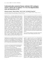
Designs, details, and methods of construction are present-
ed for the types of concrete-pedestal tanks shown in Fig. 1.2.
This document may be used in whole or in part for other tank
configurations, however, the designer should determine the
suitability of such use for other configurations and details.
1.3—Drawings, specifications, and calculations
1.3.1
Drawings and Specifications—
Construction docu-
ments should show all features of the work including the size
and position of structural components and reinforcement,
structure details, specified concrete compressive strength,
and the strength or grade of reinforcement and structural
steel. The codes and standards to which the design conforms,
the tank capacity, and the design basis or loads used in de-
sign should also be shown.
1.3.2
Design Basis Documentation—
The design coeffi-
cients and resultant loads for snow, wind and seismic forces,
and methods of analysis should be documented.
1.4—Terminology
The following terms are used throughout this document.
Specialized definitions appear in individual chapters.
Appurtenances
and accessories—
Piping, mechanical
equipment, vents, ladders, platforms, doors, lighting, and re-
lated items required for operation of the tank.
Concrete support structure
—Concrete support elements
above the top of the foundation: wall, ringbeam, and dome or
flat slab tank floor.
Construction documents
—Detailed drawings and specifi-
cations conforming to the project documents used for fabri-
cation and construction.
Foundation
—The concrete annular ring, raft, or pile or
pier cap.
Project documents
—Drawings, specifications, and gener-
al terms and conditions prepared by the specifier for procure-
ment of concrete-pedestal tanks.
Intermediate floor slabs
—One or more structural floors
above grade, typically used for storage.
Rustication
—Shallow indentation in the concrete surface,
formed by shallow insert strips, to provide architectural ef-
fect on exposed surfaces, usually
3
/
4
in. (20 mm) deep by 3
to 12 in. (75 to 300 mm) wide.
Ringbeam
—The concrete element at the top of the wall,
connecting the wall and dome, and the support for the steel
tank cone.
Wall or support wall
—The cylindrical concrete wall sup-
porting the steel tank and its contents, extending from the
foundation to the ringbeam.
Tank floor
—A structural concrete dome, concrete flat
slab, or a suspended steel floor that supports the tank con-
tents inside the support wall.
Steel liner
—A non-structural welded steel membrane
placed over a concrete tank floor and welded to the steel tank
to provide a liquid tight container; considered a part of the
steel tank.
Steel tank
—The welded steel plate water containing struc-
ture comprised of a roof, side shell, conical bottom section
outside the support wall, steel liner over the concrete tank
floor or a suspended steel floor, and an access tube.
Slab-on-grade
—Floor slab inside the wall at grade.
1.5—Notation
1.5.1
Loads—
The following symbols are used to represent
applied loads, or related forces and moments; Sections 4.3.3
and 4.4.2.
371R-3GUIDE FOR CONCRETE-PEDESTAL WATER TOWERS
D=
dead load
E=
horizontal earthquake effect
E
v
=
vertical earthquake effect
F=
stored water
G=
eccentric
load effects due to dead load and water
L=
interior floor live loads
S=
larger of snow load or minimum roof live load
T=
force due to restrained thermal movement, creep, shrinkage, or
differential settlement
W=
wind load effect
1.5.2
Variables—
The following symbols are used to rep-
resent variables. Any consistent system of measurement may
be used, except as noted.
A=
effective concrete tension area, in.
2
(mm
2
); Section 4.4.3
A
a
=
effective peak ground acceleration coefficient; Section 4.7.2
A
cv
=
effective horizontal concrete wall area resisting factored in-
plane shear
V
uw
, in.
2
(mm
2
); Section 4.8.6
A
f
=
horizontal projected area of a portion of the structure where the
wind drag coefficient
C
f
and the wind pressure
p
z
are constant;
Section 4.6.3
A
g
=
gross concrete area of a section
A
s
=
area of nonprestressed tension reinforcement
A
v
=
effective peak velocity-related ground acceleration coefficient;
Section 4.7.4
A
w
=
gross horizontal cross-sectional concrete area of wall, in.
2
(mm
2
) per unit length of circumference; Section 4.8.3
b=
width of compression face in a member
b
d
=
width of a doorway or other opening; Section 4.8.5
b
e
=
combined inside and outside base plate edge distances; Section
4.10.5
(c)
Fig 1.2—Common configurations of concrete-pedestal tanks
371R-4 MANUAL OF CONCRETE PRACTICE
b
p
=
effective
base plate width; Section 4.10.5
b
x
=
cumulative opening width in a distance of 0.78
d
w
; Section
4.8.6
C
a
=
seismic coefficient based on soil profile type and
A
a
; Section
4.7.4
C
e
=
combined height and gust response factor; Section 4.6.3
C
f
=
wind force drag coefficient; Section 4.6.3
C
r
=
roof slope
factor; Section 4.5.2
C
s
=
seismic design coefficient; Section 4.7.6
C
v
=
seismic coefficient based on soil profile type and
A
v
; Section
4.7.4
C
w
=
wall strength coefficient; Section 4.8.3
d=
distance from extreme compression to centroid tension rein-
forcement
d
c
=
distance from the extreme tension fiber to the tension steel cen-
troid, in. (mm); Section 4.4.3
d
w
=
mean diameter of concrete support wall; Sections 4.8.3, 4.8.4,
and 4.8.6
e
g
=
vertical load eccentricity, in. (mm); Section 4.2.2
e
o
=
minimum vertical load eccentricity, in. (mm); Section 4.2.2
f
c
′
=
specified compressive strength of concrete, psi (MPa)
=
square root of specified compressive strength, psi (MPa)
f
s
=
calculated stress in reinforcement at service loads, ksi (MPa);
Section 4.4.3
f
y
=
specified yield strength of reinforcing steel, psi (MPa)
F
i
=
portion of the total seismic shear
V
acting at level
i
; Sections
4.7.8 and 4.7.9
F
w
=
wind force acting on tributary area
A
f
; Section 4.6.2
F
x
=
portion of the seismic shear
V
acting at level
x
; Section 4.7.7
g=
acceleration due to gravity, 32.2 ft/sec
2
(9.8 m/sec
2
); Section
4.7.3
h=
dome tank floor thickness; Section 4.9.3
h=
wall thickness exclusive of any rustications or architectural
relief; Section 4.8
h
d
=
height of a doorway opening; Section 4.8.5
h
f
=
foundation depth measured from original ground line; Fig.
4.12.4
I=
importance factor; Sections 4.5.2 and 4.6.2
k=
structure exponent in Equation 4-10b; Section 4.7.7
k
c
=
lateral flexural stiffness of concrete support structure; Section
4.7.5
kl=
effective unsupported column length; Section 4.8.5
l
cg
=
distance from base to centroid of stored water; Sections 4.7.5
and 4.7.9
l
g
=
distance from bottom of foundation to centroid of stored water,
in. (mm); Section 4.2.2
l
i
=
distance from base to level of
F
i
; Sections 4.7.7 and 4.7.9
l
x
=
distance from base to level under consideration; Sections 4.7.7.
and 4.7.9
M
h
=
wind ovalling moment per unit of height at horizontal sections;
Section 4.8.4
M
o
=
seismic overturning moment at base; Section 4.7.9
M
u
=
factored moment; Section 4.8.6
M
x
=
seismic overturning moment at distance
l
x
above base; Section
4.7.6
n=
total number of levels within the structure; Section 4.7.7
N
=
average field standard penetration resistance for the top 100 ft
(30 m); Table 4.7.3
N
ch
=
average standard penetration resistance for cohesionless soil
layers for the top 100 ft (30 m); Table 4.7.3
p
g
=
ground snow load; Section 4.5.2
p
r
=
rain-snow surcharge; Section 4.5.2
p
z
=
wind pressure at height
z
; Section 4.6.3
p
20
=
20 lb/ft
2
(0.96 kPa) ground snow load; Section 4.5.2
P=
foundation load above grade; Fig. 4.12.4
P
nw
=
nominal axial load strength of wall, lb (N) per unit of circumfer-
ence; Section 4.8.3
P
s
=
gravity service load; Section 4.11.3
P
uw
=
factored axial wall load, lb (N) per unit of circumference; Sec-
tions 4.8.3 and 4.8.5
q
a
=
allowable bearing capacity of a shallow foundation; Section
4.12.4
q
r
=
ultimate bearing capacity of a shallow foundation; Section
4.12.4
q
s
=
wind stagnation pressure; Section 4.6.3
q
u
=
factored soil bearing pressure; Section 4.12.4
Q
a
=
allowable service load capacity of a pile or pier; Section 4.12.5
Q
r
=
ultimate capacity of a pile or pier; Section 4.12.5
Q
u
=
factored pile or pier load; Section 4.12.5
R=
seismic response modification coefficient; Section 4.7.4
R
d
=
mean meridional radius of dome tank floor; Section 4.9.3
s
u
=
average undrained shear strength in top 100 ft (30 m); Table
4.7.3
T=
fundamental period of vibration of structure, seconds; Section
4.7.5
V=
total design lateral force or shear at base of structure; Section
4.7.6
V
b
=
basic wind speed, miles per hour (m/sec); Section 4.6.3
V
n
=
nominal shear strength; Section 4.8.6
V
u
=
factored shear force; Section 4.8.6
V
uw
=
factored shear force acting on an effective shear wall; Section
4.8.6
V
x
=
lateral seismic shear force at level
x
, a distance
l
x
above base;
Section 4.7.8
w
i
=
portion of the total mass whose centroid is at level
i
, a distance
l
i
above base; Section 4.7.7
w
s
=
distributed snow load; Section 4.5.2
w
u
=
factored distributed load; Section 4.9.3
w
x
=
portion of the total mass whose centroid is at level
x
, a distance
l
x
above base; Section 4.7.7
W
c
=
weight of concrete below grade; Fig. 4.12.4
W
L
=
single lumped mass weight; Section 4.7.5
W
s
=
weight of soil below grade; Fig. 4.12.4
W
G
=
total seismic gravity load; Section 4.7.6
z=
height above ground level; Section 4.6.3
z
s
=
quantity limiting distribution of tension reinforcement; Section
4.4.2
α
c
=
constant used to compute in-plane nominal shear strength; Sec-
tion 4.8.6
β
w
=
wall slenderness coefficient; Section 4.8.3
γ
E
=
partial load factor for seismic loads; Section 4.2.3
γ
s
=
unit weight of soil; Fig. 4.12.4
θ
c
=
effective curved roof slope measured from the horizontal; Sec-
tion 4.5.1
θ
g
=
foundation tilt in degrees; Section 4.2.2
θ
r
=
roof slope in degrees measured from the horizontal; Section
4.5.1
ν
s
=
average shear wave velocity in top 100 ft (30 m); Table 4.7.3
ρ
=A
s
/bd
, ratio of nonprestressed tension reinforcement
ρ
g
=A
s
/A
g
, ratio of total nonprestressed reinforcement
ρ
h
=
ratio of horizontal distributed shear reinforcement on a vertical
plane perpendicular to
A
cv
; Section 4.8.6
ρ
v
=
ratio of vertical distributed shear reinforcement on a horizontal
plane of area
A
cv
; Section 4.8.6
φ
=
strength reduction factor; Section 4.3.2
ψ
=
wall opening ratio; Section 4.8.6
1.6 —Metric units
The in lb system is the basis for units of measurement in
this guide, and soft metric conversion is shown in parenthe-
ses.
CHAPTER 2—MATERIALS
2.1—General
Materials and material tests should conform to ACI 318,
except as modified in this document.
2.2—Cements
Cement should conform to ASTM C 150 or C 595, exclud-
ing Types S and SA, which are not intended as principal ce-
menting agents for structural concrete. The same brand and
type of cement should be used throughout the construction of
each major element.
f
c
′
371R-5GUIDE FOR CONCRETE-PEDESTAL WATER TOWERS
2.3—Aggregates
Concrete aggregates should conform to ASTM C 33 and
ACI 318. Aggregates used in the concrete support wall
should be suitable for exterior exposed surfaces. Where
sandblasting or other finishing techniques that expose aggre-
gate are used, the fine and coarse aggregate should be from
a consistent source to maintain uniformity of color.
2.4—Water
Water should conform to ASTM C 94.
2.5—Admixtures
Admixtures should conform to ACI 318.
2.6—Reinforcement
2.6.1
Bar reinforcement—
Deformed bar reinforcement
should conform to ASTM A 615/A 615M, A 617/A 617M,
or A 706/A 706M.
2.6.2
Welded wire reinforcement—
Welded wire reinforce-
ment should conform to ASTM A 185 or A 497.
CHAPTER 3—CONSTRUCTION
3.1—General
3.1.1
Reference Standard—
Concrete, formwork, rein-
forcement, and details of the concrete support structure and
foundations should conform to the requirements of ACI 318,
except as modified in this document.
3.1.2
Quality Assurance—
A quality assurance plan to ver-
ify that the construction conforms to the design requirements
should be prepared. It should include the following:
(a)
Inspection and testing required, forms for recording in-
spections and testing, and the personnel performing such work
;
(b) Procedures for exercising control of the construction
work, and the personnel exercising such control;
(c) Methods and frequency of reporting, and the distribu-
tion of reports.
3.2—Concrete
3.2.1
General—
Concrete mixtures should be suitable for
the placement methods, forming systems and the weather
conditions during concrete construction, and should satisfy the
required structural, durability and architectural parameters.
3.2.2—
Concrete quality
3.2.2.1
Water-cementitious material ratio—
The water-
cementitious material ratio should not exceed 0.50.
3.2.2.2
Specified compressive strength—
The minimum
specified compressive strength of concrete should conform
to the following:
(a) concrete support structure = 4000 psi (28 MPa);
(b) foundations and intermediate floors = 3500 psi (24
MPa); and
(c) slabs-on-grade (see Table 5.8.2).
3.2.2.3
Air-entrainment—
Concrete should be air-en-
trained in accordance with ACI 318.
3.2.3
Proportioning—
Proportioning of concrete mixtures
should conform to the requirements of ACI 318 and the pro-
cedure of ACI 211.1.
3.2.3.1
Workability—
The proportions of materials for
concrete should be established to provide adequate work-
ability and proper consistency to permit concrete to be
worked readily into the forms and around reinforcement
without excessive segregation or bleeding for the methods of
placement and consolidation employed.
3.2.3.2
Slump—
The slump of concrete provided should
be based on consideration of the conveying, placing and vi-
bration methods as well as the geometry of the component,
and should conform to the following:
(a) Concrete without high-range water-reducing admix-
tures (HRWRA) should be proportioned to produce a slump
of 4 in. (100 mm) at the point of placement.
(b) Slump should not exceed 8 in. (200 mm) after addition
of HRWRA, unless the mix has been proportioned to prevent
segregation at higher slump.
(c) The slump of concrete to be placed on an inclined sur-
face should be controlled such that the concrete does not sag
or deform after placement and consolidation.
3.2.3.3
Admixtures—
Admixtures may be used to achieve
the required properties. Admixtures should be compatible
such that their combined effects produce the required results
in hardened concrete as well as during placement and curing.
3.2.4
Concrete production—
Measuring, mixing and trans-
porting of concrete should conform to the requirements of
ACI 318 and the recommendations of ACI 304R.
3.2.4.1
Slump adjustment
—Concrete that arrives at the
project site with slump below that suitable for placing may
have water added within limits of the slump and permissible
water-cementitious material ratio of the concrete mix. The
water should be incorporated by additional mixing equal to
at least half of the total mixing time required. No water
should be added to the concrete after plasticizing or high-
range water-reducing admixtures have been added.
3.2.5
Placement—
Placing and consolidation of concrete
should conform to ACI 318, and the recommendations of
ACI 304R and ACI 309R.
3.2.5.1
Depositing and consolidation—
Placement
should be at such a rate that the concrete that is being inte-
grated with fresh concrete is still plastic. Concrete that has
partially hardened or has been contaminated by foreign ma-
terials should not be deposited. Consolidation of concrete
should be with internal vibrators.
3.2.5.2
Support wall—
Drop chutes or tremies should be
used in walls and columns to avoid segregation of the con-
crete and to allow it to be placed through the cage of rein-
forcing steel. These chutes or tremies should be moved at
short intervals to prevent stacking of concrete. Vibrators
should not be used to move the mass of concrete through the
forms.
3.2.6
Curing—
Curing methods should conform to ACI
318 and the requirements of ACI 308. Curing methods
should be continued or effective until concrete has reached
70 percent of its specified compressive strength
f
c
′
unless a
higher strength is required for applied loads. Curing should
commence as soon as practicable after placing and finishing.
Curing compounds should be membrane forming or combi-
nation curing/surface hardening types conforming to ASTM
C 309.
3.2.7
—Weather
3.2.7.1
Protection—
Concrete should not be placed in
rain, sleet, snow, or extreme temperatures unless protection
371R-6 MANUAL OF CONCRETE PRACTICE
is provided. Rainwater should not be allowed to increase
mixing water nor to damage surface finish.
3.2.7.2
Cold weather
—During cold weather, the recom-
mendations of ACI 306 should be followed.
3.2.7.3
Hot weather—
During hot weather the recom-
mendations of ACI 305R should be followed.
3.2.8
Testing, evaluation and acceptance—
Material test-
ing, type and frequency of field tests, and evaluation and ac-
ceptance of testing should conform to ACI 318.
3.2.8.1
Concrete strength tests—
At least four cylinders
should be molded for each strength test required. Two cylin-
ders should be tested at 28 days for the strength test. One cyl-
inder should be tested at 7 days to supplement the 28-day
tests. The fourth cylinder is a spare to replace or supplement
other cylinders. Concrete temperature, slump, and air con-
tent measurements should be made for each set of cylinders.
Unless otherwise specified in the project documents, sam-
pling of concrete should be at the point of delivery.
3.2.8.2
Early-age concrete strength—
Where knowledge
of early-age concrete strength is required for construction
loading, field-cured cylinders should be molded and tested,
or one of the following non-destructive test methods should
be used when strength correlation data are obtained:
(a)
Penetration resistance in accordance with ASTM C 803;
(b) Pullout strength in accordance with ASTM C 900;
(c) Maturity-factor method in accordance with ASTM C
1074.
3.2.8.3
Reporting
—A report of tests and inspection re-
sults should be provided. Location on the structure repre-
sented by the tests, weather conditions, and details of storage
and curing should be included.
3.2.9—
Joints and embedments
3.2.9.1
Construction joints—
The location of construc-
tion joints and their details should be shown on construction
drawings. Horizontal construction joints in the support wall
should be approximately evenly spaced. The surface of con-
crete construction joints should be cleaned and laitance re-
moved.
3.2.9.2
Expansion joints—
Slabs-on-grade and intermedi-
ate floor slabs not structurally connected to the support struc-
ture should be isolated from the support structure by
premolded expansion joint filler.
3.2.9.3
Contraction joints—
Contraction joints are only
used with slabs-on-grade (see Section 5.8.2.3).
3.2.9.4
Embedments—
Sleeves, inserts, and embedded
items should be installed prior to concrete placement, and
should be accurately positioned and secured against dis-
placement.
3.3—Formwork
3.3.1
—General
Formwork design, installation, and removal should con-
form to the requirements of ACI 318 and the recommenda-
tions of ACI 347R. Formwork should ensure that concrete
components of the structure will conform to the correct di-
mensions, shape, alignment, elevation and position within
the established tolerances. Formwork systems should be de-
signed to safely support construction and expected environ-
mental loads, and should be provided with ties and bracing
as required to prevent the leakage of mortar and excessive
deflection.
3.3.1.1
Facing material
—Facing material of forms used
above finished grade should be metal, or plywood faced with
plastic or coated with fiberglass. Any form material may be
used for below-grade applications.
3.3.1.2
Chamfers
—Exposed corners should be formed
with chamfers
3
/
4
in. (20 mm) or larger.
3.3.1.3
Concrete strength
—The minimum concrete
compressive strength
required for safe removal of any sup-
ports for shored construction, or the safe use of construction
embedments or attachments should be shown on construc-
tion drawings, or instructions used by field personnel.
3.3.1.4
Cleaning and coating
—Form surfaces should be
cleaned of foreign materials and coated with a non-staining
release agent prior to placing reinforcement.
3.3.1.5
Inspection
—Prior to placing concrete, forms
should be inspected for surface condition, accuracy of align-
ment, grade and compliance with tolerance, reinforcing steel
clearances and location of embedments. Shoring and bracing
should be checked for conformance to design.
3.3.2—
Foundations
3.3.2.1
Side forms
—Straight form panels that circum-
scribe the design radius may be used to form circular foun-
dation shapes. Circular surfaces below final ground level
may have straight segments that do not exceed 30 deg of arc,
and surfaces exposed to view may have straight segments
that do not exceed 15 deg of arc.
3.3.2.2
Top forms
—Forms should be provided on top
sloping surfaces steeper than 1 vertical to 2.5 horizontal, un-
less it can be demonstrated that the shape can be adequately
maintained during concrete placement and consolidation.
3.3.2.3
Removal
—Top forms on sloping surfaces may be
removed when the concrete has attained sufficient strength
to prevent plastic movement or deflection. Side forms may
be removed when the concrete has attained sufficient
strength such that it will not be damaged by removal opera-
tions or subsequent load.
3.3.3—
Support wall
3.3.3.1
Wall form
—The support wall should be con-
structed using a form system having curved, prefabricated
form segments of the largest practical size in order to mini-
mize form panel joints. Formwork should be designed for
lateral pressures associated with full height plastic concrete
head. Bracing should be provided for stability, construction
related impact loading, and wind loads. Working platforms
that allow access for inspection and concrete placement
should be provided.
3.3.3.2
Deflection
—Deflection of facing material be-
tween studs as well as studs and walers should not exceed 1/
400 times the span during concrete placement.
3.3.3.3
Rustications
—A uniform pattern of vertical and
horizontal rustications to provide architectural relief is rec-
ommended for exterior wall surfaces exposed to view. Con-
struction joints should be located in rustications.
3.3.3.4
Form ties
—Metal form ties that remain within
the wall should be set back 1
1
/
2
in. (40 mm) from the con-
crete surface.
371R-7GUIDE FOR CONCRETE-PEDESTAL WATER TOWERS
3.3.3.5
Removal
—Vertical formwork not supporting the
weight of the component may be removed when the concrete
has reached sufficient strength such that it will not be dam-
aged by the removal operation and subsequent loads.
3.3.4—
Tank floor
3.3.4.1
Design
—Formwork for the flat slab or dome tank
floor should be designed to support construction loads in-
cluding weight of forms, plastic concrete, personnel, equip-
ment, temporary storage, and impact forces. Unsymmetrical
placement of concrete should be considered in the design.
Camber to offset concrete weight should be provided where
deflection would result in out-of-tolerance construction.
3.3.4.2
Removal
—Forms should remain in place until the
concrete has gained sufficient strength not to be damaged by
removal operations and subsequent loads. The minimum re-
quired concrete strength for form removal should be shown
on construction drawings or instructions issued to the field.
3.4—Reinforcement
3.4.1
General—
Reinforcement should be clearly indicated
on construction drawings and identified by mark numbers
that are used on the fabrication schedule. Location, spacing
as well as lap splice lengths of reinforcement, and concrete
cover should be shown. Symbols and notations should be
provided to indicate or clarify placement requirements.
3.4.2
Fabrication—
The details of fabrication, including
hooks and minimum diameter of bends, should conform to
the requirements of ACI 318 and ACI 315.
3.4.3
Placement—
Reinforcement should be accurately po-
sitioned, supported and securely tied and supported to pre-
vent displacement of the steel during concrete placement.
Bar spacing limits and surface condition of reinforcement
should conform to the requirements of ACI 318.
3.4.3.1
Concrete cover
—The following minimum con-
crete cover should be provided for reinforcement in cast in
place concrete for No. 11 (36) bar, W31 (MW200) or D31
(MD200) wire, and smaller. Cover is measured at the thin-
nest part of the wall, at the bottom of rustication grooves, or
between the raised surfaces of architectural feature panels.
3.4.3.2
Supports
—Supports for reinforcement should
conform to the following:
(a) The number of supports should be sufficient to prevent
out-of-tolerance deflection of reinforcement, and to prevent
overloading any individual support;
(b) Shallow foundation reinforcement placed adjacent to
the ground or working slab should be supported by precast
concrete block, metal or plastic bar supports;
(c) Reinforcement adjacent to formwork should be sup-
ported by metal or plastic bar supports. The portions of bar
supports within
1
/
2
in. (13 mm) of the concrete surface
should be noncorrosive or protected against corrosion;
(d) Support wall reinforcement should be provided with
plastic supports. Maximum spacing of supports for welded
wire fabric should be 5 ft (1.5 m) centers, horizontally and
vertically.
3.4.4
—Development and splices
3.4.4.1
Development and splice lengths—
Development
and splices of reinforcement should be in accordance with
ACI 318. The location and details of reinforcement develop-
ment and lap splices should be shown on construction draw-
ings.
3.4.4.2
Welding—
Welding of reinforcement should con-
form to AWS D1.4. A full welded splice should develop 125
percent of the specified yield strength of the bar. Reinforce-
ment should not be tack welded.
3.4.4.3
Mechanical connections—
The type, size, and lo-
cation of any mechanical connections should be shown on
construction drawings. A full mechanical connection should
develop in tension or compression, as required, 125 percent
of the specified yield strength of the bar.
3.5—Concrete finishes
3.5.1
—Surface repair
3.5.1.1
Patching materials—
Concrete should be patched
with a proprietary patching material or site-mixed portland
cement mortar. Patching material for exterior surfaces
should match the surrounding concrete in color and texture.
3.5.1.2
Repair of defects—
Concrete should be repaired
as soon as practicable after form removal. Honeycomb and
other defective concrete should be removed to sound con-
crete and patched.
3.5.1.3
Tie holes—
Tie holes should be patched, except
that manufactured plastic plugs may be used for exterior sur-
faces.
3.5.2
Formed surfaces—
Finishing of formed surfaces
should conform to the following:
(a) Exterior exposed surfaces of the support structure and
foundations should have a smooth as-cast finish, unless a
special formed finish is specified;
(b) Interior exposed surfaces of the support structure
should have a smooth as-cast finish;
(c) Concrete not exposed to view may have a rough as-cast
finish.
3.5.2.1
Rough as-cast finish
—Any form facing material
may be used, provided the forms are substantial and suffi-
ciently tight to prevent mortar leakage. The surface is left
with the texture imprinted by the form. Defects and tie holes
should be patched and fins exceeding
1
/
4
in. (6 mm) in height
should be removed.
Minimum cover,
in. (mm)
(a) Concrete foundations permanently exposed to
earth:
Cast against earth 3 (75)
Cast against forms or mud slabs, or top
reinforcement:
No. 6 (19) bar, W45 (MW290) or D45 (MD290)
wire, and larger
2 (50)
No. 5 (16) bar, W31 (MW200) or D31 (MD200)
wire, and smaller
1
1
/
2
(40)
(b) Concrete support structure:
Exterior surfaces:
No. 6 (19) bar, W45 (MW290) or D45 (MD290)
wire, and larger
2 (50)
No. 5 (16) bar, W31 (MW200) or D31 (MD200)
wire, and smaller
1
1
/
2
(40)
Interior surfaces 1 (25)
Sections designed as beams or colums 1
1
/
2
(40)
(c) Tank floors and intermediate floor slabs 1
1
/
2
(40)
371R-8 MANUAL OF CONCRETE PRACTICE
3.5.2.2
Smooth as-cast finish
—Form facing material and
construction should conform to Section 3.3. The surface is
left with the texture imprinted by the form. Defects and tie
holes should be patched and fins should be removed by chip-
ping or rubbing.
3.5.2.3
Special form finish
—A smooth as-cast finish is
produced, after which additional finishing is performed. The
type of additional finishing required should be specified.
3.5.3
Trowel finishes—
Unformed concrete surfaces
should be finished in accordance with the following:
• Slabs-on-grade and intermediate floor slabs—steel
trowel;
• Dome and flat slab tank floors—floated;
• Foundations—floated;
• Surfaces receiving grout—floated.
3.6—Tolerances
3.6.1
Concrete tolerances—
Tolerances for concrete and re-
inforcement should conform to ACI 117 and the following:
(a) Dimensional tolerances for the concrete support struc-
ture:
Variation in thickness:
wall: –3.0 percent, +5.0 percent
dome: –6.0 percent, +10 percent
Support wall variation from plumb:
in any 5 ft (1.6 m) of height (1/160):
3
/
8
in. (10 mm)
in any 50 ft (16 m) of height (1/400): 1.5 in.
(40 mm)
maximum in total height: 3 in. (75 mm)
Support wall diameter variation: 0.4 percent
not to exceed 3 in. (75 mm)
Dome tank floor radius variation: 1.0 percent
Level alignment variation:
from specified elevation: 1 in. (25 mm)
from horizontal plane:
1
/
2
in. (13 mm)
(b) The offset between adjacent pieces of formwork facing
material should not exceed the following:
Exterior exposed surfaces:
1
/
8
in. (3 mm)
Interior exposed surfaces:
1
/
4
in. (6 mm)
Unexposed surfaces:
1
/
2
in. (13 mm)
(c) The finish tolerance of troweled surfaces should not
exceed the following when measured with a 10 ft (3 m)
straightedge or sweep board:
Exposed floor slab:
3
/
8
in. (6 mm)
Tank floors:
3
/
4
in. (20 mm)
Concrete support for suspended steel floor tank:
1
/
4
in.
(6 mm)
3.6.2
Out-of-tolerance construction—
The effect on the
structural capacity of the element should be determined by
the responsible design professional if construction does not
conform to Section 3.6.1. When structural capacity is not
compromised, repair or replacement of the element is not re-
quired unless other governing factors, such as lack of fit and
aesthetics, require remedial action.
3.7—Foundations
3.7.1
Reinforced Concrete—
Concrete, formwork, and re-
inforcement should conform to the applicable requirements
of Chapter 3.
3.7.2
—Earthwork
3.7.2.1
Excavations
—
Foundation excavations should be
dry and have stable side slopes. Applicable safety standards and
regulations should be followed in constructing excavations.
3.7.2.2
Inspection
—Excavations should be inspected
prior to concrete construction to ensure that the material en-
countered reflects the findings of the geotechnical report.
3.7.2.3
Mud mats
—A lean concrete mud mat is recom-
mended to protect the bearing stratum, and to provide a
working surface for placing reinforcement.
3.7.2.4
Backfill
—
Backfill should be placed and com-
pacted in uniform horizontal lifts. Fill inside the concrete
wall should conform to Section 5.8.2.4. Fill material out-
side the concrete wall may be unclassified soils free of or-
ganic matter and debris. Backfill should be compacted to
90 to 95 percent standard Proctor density (ASTM D 698)
or
greater.
3.7.2.5
Grading—
Site grading around the tank should
provide positive drainage away from the tank to prevent
ponding of water in the foundation area.
3.7.3
Field inspection of deep foundations—
Field inspec-
tion by a qualified inspector of foundations and concrete
work should conform to the following:
(a) Continuous inspection during pile driving and place-
ment of concrete in deep foundations;
(b) Periodic inspection during construction of drilled piers
or piles, during placement of concrete, and upon completion
of placement of reinforcement.
3.8—Grout
3.8.1
Steel liner—
Unformed steel liner plates that do not
match the shape of the concrete floor may be used, provided
the liner plate is grouted after welding. The steel liner should
be constructed with a 1 in. (25 mm) or larger grout space be-
tween the liner plate and the concrete member. The space
should be completely filled with a flowable grout using a
procedure that removes entrapped air. Provide anchorage in
areas where the grout pressure is sufficient to lift the plate.
3.8.2
Base plate—
A base plate used for the steel bottom
configuration should be constructed with a 1 in. (25 mm) or
larger grout space between the base plate and the concrete.
The space should be completely filled with a non-shrink,
non-metallic grout conforming to Section 4.10.5.6. Grout
should be placed and achieve required strength before hy-
drotesting the tank.
CHAPTER 4—DESIGN
4.1—General
4.1.1
Scope—
This chapter identifies the minimum re-
quirements for the design and analysis of a concrete-pedestal
elevated water tank incorporating a concrete support struc-
ture, a steel storage tank, and related elements.
4.1.2
Design of concrete support structure—
Analysis and
design of the concrete support structure should conform to
ACI 318, except as modified here. Design of the concrete
support structure elements should conform to Sections 4.8
through 4.10.
371R-9GUIDE FOR CONCRETE-PEDESTAL WATER TOWERS
4.1.3
Design of steel storage tank—
The materials, design,
fabrication, erection, testing, and inspection of the steel stor-
age tank should conform to recognized national standards.
4.1.4
—Design of other elements
4.1.4.1
Concrete members
—Design of concrete mem-
bers such as foundations, floor slabs, and similar structural
members should conform to ACI 318, and the requirements
of Sections 4.11 and 5.8.
4.1.4.2
Non-concrete members
—Design of non-concrete
related elements such as appurtenances, accessories and
structural steel framing members should conform to recog-
nized national standards for the type of construction.
4.1.4.3
Safety related components
—Handrails, ladders,
platforms, and similar safety related components should con-
form to the applicable building code, and to Occupational
Safety and Health Administration standards.
4.1.5
Unit weight—
The unit weight of materials used in
the design for the determination of gravity loads should be as
follows, except where materials are known to differ or spec-
ifications require other values:
(a) Reinforced concrete: 150 lb/ft
3
(2400 kg/m
3
);
(b) Soil backfill: 100 lb/ft
3
(1600 kg/m
3
);
(c) Water: 62.4 lb/ft
3
(1000 kg/m
3
);
(d) Steel: 490 lb/ft
3
(7850 kg/m
3
);
4.2—Loads
4.2.1
General—
The structure should be designed for loads
not less than those required for an ASCE 7 Category IV
structure, or by the applicable building code.
4.2.2
Structural loads—
The loads in Section 4.2.2.1
through 4.2.2.8 should be considered to act on the structure
as a whole.
4.2.2.1
Dead loads
—The weight (mass) of structural
components and permanent equipment.
4.2.2.2
Water load—
The load produced by varying water
levels ranging from empty to overflow level.
4.2.2.3
Live loads
—Distributed and concentrated live
loads acting on the tank roof, access areas, elevated plat-
forms, intermediate floors or equipment floors. The distrib-
uted roof live load should be the greater of snow load
determined in Section 4.5, or 15 lb/ft
2
(0.72 kPa) times the
horizontal projection of the roof surface area to the eave line.
Unbalanced loading should be considered in the design of
the roof and its supporting members.
4.2.2.4
Environmental loads
—Environmental loads
should conform to:
(a) Snow loads: Section 4.5;
(b) Wind forces: Section 4.6;
(c) Seismic forces: Section 4.7.
4.2.2.5
Vertical load eccentricity—
Eccentricity of dead
and water loads that cause additional overturning moments
to the structure as a whole should be accounted for in the de-
sign. The additional overturning moment is the dead and wa-
ter load times the eccentricity
e
g
, which should not be taken
as less than
(4-1a)
The minimum vertical load eccentricity
e
o
is 1 in. (25 mm).
Where tilting of the structure due to non-uniform settle-
ment is estimated to exceed 1/800, the eccentricity
e
g
should
not be taken as less than
(4-1b)
4.2.2.6
Construction loads
—Temporary loads resulting
from construction activity should be considered in the design
of structural components required to support construction
loads.
4.2.2.7
Creep, shrinkage, and temperature
—The effects
of creep, shrinkage, and temperature effects should be con-
sidered. ACI 209R provides guidance for these conditions.
4.2.2.8
Future construction—
Where future construction,
such as the addition of intermediate floors is anticipated, the
load effects should be included in the original design. Future
construction dead and live loads should be included in the
Group 1 load combinations. Only that portion of the dead
load
D
existing at the time of original construction should be
included in the Group 2 load combinations.
4.2.3
Factored load combinations—
Load factors and load
combinations for the Strength Design Method should con-
form to the following. The load terms are as defined in Sec-
tion 1.6.1.
4.2.3.1
Group 1 load combinations
—Where the structur-
al effects of applied loads are cumulative the required
strength should not be less than:
Load Combination:
U1.1 1.4
D
+ 1.6
F
U1.2 1.4(
D
+
G
) + 1.6
F
+ 1.7(
S
+
L
)
U1.3 1.1(
D
+
G
) + 1.2
F
+ 1.3(
L
+
W
)
U1.4
γ
E
[1.2(
D
+
F
) + 0.5(
G
+
L
) +
E
] +
E
v
4.2.3.2
Group 2 load combinations
—Where
D
,
L
, or
F
reduce the effect of
W
or
E
, as in uplift produced by overturn-
ing moment, the required strength should not be less than:
Load Combination:
U2.1 0.9
D
+ 1.3
W
U2.2
γ
E
[0.9(
D
+
F
) +
E
] +
E
v
4.2.3.3
Differential settlement, creep, shrinkage, and
temperature
—Where structural effects of differential settle-
ment, creep, shrinkage or temperature effects are significant:
1.4
T
should be included with Load Combinations U1.1 and
U1.2, and 1.1
T
should be included with Load Combinations
U1.3 and U1.4. Where structural effects
T
are significant:
1.1
T
should be included with Group 2 loads when
T
is addi-
tive to
W
or
E
.
4.2.3.4
Vertical seismic load effect
—The vertical seismic
load effect
E
v
in Eq. U1.4 and U2.2 should conform to the re-
quirements of the project documents, or the applicable build-
ing code. Where ASCE 7 is specified,
E
v
is
γ
E
0.5C
a
(D + F)
.
4.2.3.5
Partial seismic load factor
—The partial seismic
load factor
γ
E
should conform to the requirements of the
project documents, or the applicable building code. Where
ASCE 7 is specified,
γ
E
is 1.1 for concrete elements.
e
g
e
o
l
g
400
+=
e
g
e
o
l
g
1
800
θ
g
tan+
+=
371R-10 MANUAL OF CONCRETE PRACTICE
4.2.4
Unfactored load combinations—
Unfactored service
load combinations should conform to the following. The
load terms are as defined in Section 1.6.1.
4.2.4.1
Group 1 load combinations
—Where the structur-
al effects of applied loads are cumulative the unfactored ser-
vice load combination should not be less than:
Load Combination:
S1.1
D + F
S1.2
D + F + G + S + L
S1.3 0.75(
D + F + G + L + W
)
S1.4 0.75[
D + F + G + L + E
]
+ E
V
4.2.4.2
Group 2 load combinations
—Where
D, L
, or
F
reduce the effect of
W
or
E
, as in uplift produced by overturn-
ing moment, the required strength should not be less than:
Load Combination:
S2.1 0.75(
D + W
)
S2.2 0.75[
D + F + E
]
+ E
v
4.2.4.3
Differential settlement, creep, shrinkage, and
temperature
—Where structural effects of differential settle-
ment, creep, shrinkage or temperature effects are significant:
1.0
T
should be included with Load Combinations S1.1 and
S1.2, and 0.75
T
should be included with Load Combinations
S1.3 and S1.4. Where structural effects
T
are significant:
0.75
T
should be included with Group 2 loads when
T
is ad-
ditive to
W
or
E
.
4.2.4.4
Vertical seismic load effect
—The vertical seis-
mic load effect
E
v
in Eq. S1.4 and S2.2 should conform to the
requirements of the project documents, or the applicable
building code. Where ASCE 7 is specified,
E
v
is 0.75 [
0.5C
a
(
D + F
)]
.
4.3—Strength requirements
4.3.1
General—
Concrete portions of the structure should
be designed to resist the applied loads that may act on the
structure and should conform to this document.
4.3.1.1
Specified concrete strength—
Specified compres-
sive strength
f
c
′
of concrete components should conform to
Section 3.2.2.2 and applicable sections of Chapter 4.
4.3.1.2
Specified strength for reinforcement—
The speci-
fied yield strength of reinforcement
f
y
should not exceed
80,000 psi (550 MPa).
4.3.2
—Design methods
4.3.2.1
Strength design method—
Structural concrete
members should be proportioned for adequate strength in ac-
cordance with the Strength Design provisions of ACI 318
and this document. Loads should not be less than the factored
loads and forces in Section 4.2.3. Strength reduction factors
φ
should conform to ACI 318 and to applicable sections of
Chapter 4.
4.3.2.2
Alternate design method
—
The Alternate Design
Method of ACI 318 is an acceptable method for design. Un-
factored load combinations should conform to Section
4.2.4.
4.3.3
—Minimum reinforcement
4.3.3.1
Flexural members
—Where flexural reinforce-
ment is required by analysis in the support structure and
foundations supported by piling and drilled piers, the mini-
mum reinforcement ratio
p
should not be less than 3
/f
y
nor 200
/f
y
in in lb units (0.25
/f
y
nor 1.4
/f
y
in SI units).
A smaller amount of reinforcement may be used if at every
section the area of tensile reinforcement provided is at least
one-third greater than that required by analysis.
4.3.3.2
Direct tension members
—In regions of signifi-
cant direct tension the minimum reinforcement ratio
p
g
should not be less than 5
/f
y
in in lb units (0.42
/f
y
in
SI units). A smaller amount of reinforcement may be used if
the area of tensile reinforcement provided is at least one-
third greater than that required by analysis.
4.4—Serviceability requirements
4.4.1
General—
Concrete portions of the structure should
conform to this document to ensure adequate performance at
service loads. The following should be considered.
(a) Deflection of flexural beam or slab elements should
conform to ACI 318.
(b) Control of cracking should conform to Section 4.4.2
and applicable sections of Chapter 4.
(c) Settlement of foundations should conform to Sections
4.12.3 and 4.12.5.
4.4.2
Control of cracking—
Cracking and control of crack-
ing should be considered at locations where analysis indi-
cates flexural tension or direct tension stresses occur.
Where control of cracking is required, sections should be
proportioned such that quantity
z
s
does not exceed 145 kips
per inch (25,400 N/mm) for sections subjected to flexure, or
130 kips per in. (22,800 N/mm) for sections subjected to di-
rect tension. The quantity
z
s
is determined by:
(4-2)
Calculated stress in reinforcement
f
s
is for Load Combina-
tion S1.1 in Section 4.2.4.1. Alternatively,
f
s
may be taken as
60 percent of the specified yield strength
f
y
. The clear cover
used in calculating the distance from the extreme tension fi-
ber to the tension steel centroid
d
c
should not exceed 2 in. (50
mm) even though the actual cover is larger.
4.5—Snow Loads
4.5.1
—General
4.5.1.1
Scope—
This section covers determination of
minimum snow loads for design and is based on ASCE 7 for
Category IV structures. Larger loads should be used where
required by the applicable building code.
4.5.1.2
Definitions
—Certain terms used in this section
are defined as follows:
Crown
—highest point of the roof at centerline of tank.
Eaves
—highest level at which the tank diameter is maxi-
mum; or the 70-deg point of the roof slope of curved or con-
ical roofs, if present. The 70-deg point is the radius at which
the roof slope is 70 deg measured from the horizontal.
Cone roof—
monoslope roof having a constant slope from
crown to eaves.
Conical roof—
a cone roof combined with an edge cone or
a doubly curved edge segment.
Curved roof
—dome, ellipsoidal, or other continuous shell
roofs with increasing slope from crown to eaves; or the dou-
bly curved portion of a conical roof.
f
c
′
f
c
′
f
c
′
f
c
′
z
s
f
s
d
c
A
3
=
371R-11GUIDE FOR CONCRETE-PEDESTAL WATER TOWERS
Roof slope
θ
r
—
roof slope at a point measured from the
horizontal.
Effective curved roof slope
θ
c
—
slope of a straight line
from the eaves (or the 70-deg point if present) to the crown
of a curved roof, or a conical roof.
4.5.1.3
Limitations
—The provisions of Section 4.5 are
applicable to cone, conical, and curved roofs concave down-
ward without steps or abrupt changes in elevation.
4.5.2
Roof snow load—
The unfactored snow load acting
on the structure is the sum of the uniformly distributed snow
load
w
s
acting on any portion of a roof times the horizontal
projected area on which
w
s
acts. The uniformly distributed
snow load
w
s
is the larger value determined in Sections
4.5.2.1 and 4.5.2.2.
4.5.2.1
Sloped roof snow load
—Portions of a roof having
a slope
θ
r
exceeding 70 deg should be considered free of
snow load. Where roof slope
θ
r
is 70 deg or less, the distrib-
uted snow load is given by
w
s
=
0.76
C
r
I p
g
(4-3a)
The ground snow load
p
g
is in accordance with Section
4.5.2.3, and the roof slope factor
C
r
is in accordance with
Section 4.5.2.4. The snow importance factor
I
is 1.2.
4.5.2.2
Minimum snow load
—The minimum snow load
acting on cone roofs with slope
θ
r
less than 15 deg and
curved roofs with slope
θ
c
less than 10 deg is the larger value
determined from Eq. (4-3b) and (4-3c) when the ground
snow load
p
g
is greater than zero
w
s
= C
r
p
20
I
for
p
g
>
p
20
(4-3b)
w
s
=
C
r
(
I
p
g
+
p
r
) for
p
g
≤
p
20
(4-3c)
where
p
20
=
20 lb/ft
2
(0.96 kPa) ground snow load
The rain-snow surcharge
p
r
is 5 lb/ft
2
(0.24 kPa). For roof
slopes steeper than 1 vertical to 24 horizontal (greater than
2.38 deg from the horizontal) it may be reduced by
0.24 I p
g
up to a maximum reduction of 5 lb/ft
2
(0.24 kPa).
4.5.2.3
Ground snow load
—The ground snow load
p
g
should be based on an extreme-value statistical analysis of
weather records using a 2 percent annual probability of being
exceeded (50-year mean recurrence interval). In the contig-
uous United States and Alaska ground snow load
p
g
should
be determined from Fig. 7-1 or Table 7-1 in ASCE 7.
4.5.2.4
Roof slope factor—
The roof slope factor at any
point on the roof is given by:
C
r
=
1.27
–
θ
r
/
55, not greater 1.0 nor less than zero. For
curved roofs or portions of roofs that are curved the distribu-
tion of snow load should be assumed to vary linearly be-
tween points at 15 and 30 deg, and the eaves. Linear
interpolation should be used where the roof slope at the
eaves is less than 70 deg.
4.6—Wind forces
4.6.1
Scope—
This section covers determination of mini-
mum service load wind forces for design, and is based on
ASCE 7 for Category IV structures. Larger loads should be
used where required by the applicable building code.
4.6.2
—Wind speed
4.6.2.1
Basic wind speed
—The basic wind speed
V
b
is
the 3-sec gust speed at 33 ft (10 m) above ground for Expo-
sure C category, and is associated with a 2 percent annual
probability of being exceeded (50-yr mean recurrence inter-
val). In the contiguous United States and Alaska basic wind
speed
V
b
may be determined from Fig. 6-1 in ASCE 7.
4.6.2.2
Wind speed-up
—Wind speed-up over hills and es-
carpments should be considered for structures sited on the up-
per half of hills and ridges or near the edge of escarpments.
4.6.3
Design wind force—
The service load wind force
W
acting on the structure is the sum of the forces calculated
from Section 4.6.3.1.
4.6.3.1—The design wind force
F
w
acting on tributary
area
A
f
is
F
w
=
C
f
p
z
A
f
(4-4)
where
C
f
=
wind force drag coefficient
=
0.6, for cylindrical surfaces
=
0.5, for double curved surfaces or cones with an apex
angle > 30 deg.
The wind pressure
p
z
at height
z
above ground level is in
accordance with Section 4.6.3.2.
4.6.3.2—Wind pressure
p
z
is
p
z
= C
e
q
s
I
not less than 30 lb/ft
2
(1.44 kPa) (4-5)
where
q
s
=
0.00256
(
V
b
)
2
, lb/ft
2
;
wind stagnation pressure
q
s
=
0.000613
(
V
b
)
2
, kPa;
wind stagnation pressure
in SI
units
The basic wind speed
V
b
is in accordance with Section
4.6.2.1, and the combined height and gust response factor
C
e
is in accordance with Table 4.6.3(a). The wind importance
factor
I
is 1.15.
4.6.3.3
Exposure category
—The wind exposure in
which the structure is sited should be assessed as being one
of the following:
(a) Exposure B: urban and suburban areas. Characterized
by numerous closely spaced obstructions having the size of
single-family dwellings or larger. This exposure is limited to
areas where the terrain extends in all directions a distance of
1500 ft (460 m) or 10 times the structure height, whichever
is greater;
(b) Exposure C: flat and generally open terrain, with scattered
obstructions having heights generally less than 30 ft (9 m);
(c) Exposure D: flat, unobstructed areas exposed to wind
flowing over open water for a distance of at least one mile
(1600 m). This exposure extends inland from the shoreline a
distance of 1500 ft (460 m) or 10 times the structure height,
whichever is greater.
371R-12 MANUAL OF CONCRETE PRACTICE
4.7—Seismic forces
4.7.1
—General
4.7.1.1
Scope—
This section covers determination of
minimum factored seismic forces for design, and is based on
ASCE 7 Category IV structures. Larger loads should be used
where required by the applicable building code.
4.7.1.2
Definitions
—Certain terms used in this section
are defined as follows:
Base
—The level at which the earthquake motions are con-
sidered to be imparted to the structure.
Base Shear
V
—The total design lateral force or shear at
base of structure.
Gravity load
W
G
—Dead load and applicable portions of
other loads defined in Section 4.7.6.3 that is subjected to
seismic acceleration.
4.7.1.3
Limitations
—The provisions of Section 4.7 are
applicable to sites where the effective peak ground accelera-
tion coefficient
A
v
is 0.4 or less.
4.7.2
Design seismic force—
The factored design seismic
forces acting on the structure should be determined by one of
the following procedures. Structures should be designed for
seismic forces acting in any horizontal direction.
4.7.2.1
Equivalent lateral force procedure
—The equiva-
lent lateral force procedure of Section 4.7.6 may be used for
all structures.
4.7.2.2
Alternative procedures
—Alternative lateral force
procedures, using rational analysis based on well established
principles of mechanics, may be used in lieu of the equiva-
lent lateral force procedure. Base shear
V
used in design
should not be less than 70 percent of that determined by Sec-
tion 4.7.6.
4.7.2.3—Seismic analysis is not required where the effec-
tive peak velocity-related acceleration coefficient
A
v
is less
than 0.05.
4.7.3
Soil profile type—
Where the peak effective velocity-
related ground acceleration
A
v
is 0.05 or greater, the soil pro-
file type should be classified in accordance with Table 4.7.3
by a qualified design professional using the classification
procedure given in ASCE 7.
4.7.4
—Seismic coefficients
4.7.4.1
Effective peak ground acceleration coefficients
—
The effective peak acceleration
A
a
and effective peak veloc-
ity-related acceleration coefficient
A
v
should be determined
from Maps 9-1 and 9-2, respectively, of ASCE 7. Where site-
specific ground motions are used or required, they should be
developed on the same basis, with 90 percent probability of
not being exceeded in 50 years.
4.7.4.2
Seismic acceleration coefficients
—Seismic ac-
celeration coefficients
C
a
and
C
v
should be determined from
Table 4.7.4.
At sites with soil profile F, seismic coefficients should be
determined by site specific geotechnical investigation and
dynamic site response analyses.
4.7.4.3
Response modification coefficient
—The re-
sponse modification coefficient
R
used in design should not
exceed 2.0.
4.7.5
—Structure period
4.7.5.1
Fundamental period
—The fundamental period
of vibration
T
of the structure should be established using the
structural properties and deformational characteristics of the
resisting elements in a properly substantiated analysis.
4.7.5.2
Single lumped-mass approximation
—The struc-
ture period
T
may be calculated from Eq. (4-6) when the wa-
ter load is 80 percent or more of the total gravity load
W
G
(4-6)
The single lumped-mass structure weight
W
L
consists of:
(a) Self-weight of the tank and tank floor;
(b) Maximum of two-thirds the self-weight of concrete
support wall; and
(c) Water load.
4.7.6
—Equivalent lateral force procedure
4.7.6.1
Seismic base shear
—The total seismic shear
V
in
a given direction is determined by
V = C
s
W
G
(4-7)
The seismic response coefficient
C
s
is in accordance with
Section 4.7.6.2, and the gravity load W
G
is in accordance
with Section 4.7.6.3.
Table 4.6.3—Combined height and gust factor:
C
e
Height above ground level,
ft (m) Exposure B Exposure C Exposure D
Less than 75 (23) 0.73 1.01 1.16
100 (30) 0.79 1.07 1.22
150 (46) 0.89 1.17 1.31
200 (61) 0.96 1.24 1.37
250 (76) 1.03 1.30 1.43
300 (91) 1.08 1.36 1.47
Table 4.7.3—Soil profile type classification
Soil profile type
ν
s
,
ft/sec (m/sec)
N
or
N
ch
s
u
,
lb/ft
2
(kPa)
A. Hard rock
> 5000
(> 1500)
Not
applicable
Not
applicable
B. Rock
2500 to 5000
(760 to 1500)
Not
applicable
Not
applicable
C. Very dense soil and soft
rock
1200 to 2500
(370 to 760)
> 50
> 2000
( > 96)
D. Stiff soil
600 to 1200
(180 to 370)
15 to 50
1000 to 2000
(48 to 96)
E. Soil
< 600
(< 180)
< 15
< 1000
(< 48)
F. Soils requiring site
specific evaluation
1. Soils vulnerable to potential failure or
collapse
2. Peats and/or highly organic clays
3. Very high plasticity clays
4. Very thick soft/medium clays
ν
s
= Average shear wave velocity in top 100 ft (30 m).
N
= Average field standard penetration resistance for the top 100 ft
(30 m).
N
ch
= Average standard penetration resistance for cohesionless soil
layers for the top 100 ft (30 m).
s
u
= Average undrained shear strength in top 100 ft (30 m).
T
2
π
W
L
gk
c
=
371R-13GUIDE FOR CONCRETE-PEDESTAL WATER TOWERS
4.7.6.2
Seismic response coefficient
—The seismic re-
sponse coefficient
C
s
is the smaller value determined from
Eq. (4-8a) and (4-8b)
(4-8a)
(4-8b)
The minimum value of
C
s
should not be less than
C
s
= 0.5
C
a
(4-9)
4.7.6.3
Gravity load
—The gravity load
W
G
includes: the
total dead load above the base, water load, and a minimum
of 25 percent of the floor live load in areas used for storage.
4.7.7
Force distribution—
The total lateral seismic force
V
should be distributed over the height of the structure in pro-
portion to the structure weight by Eq. (4-10a) when the dead
load is less than approximately 25 percent of the total weight.
Where the dead is greater the distribution of lateral seismic
force should be determined Eq. (4-10b)
(4-10a)
(4-10b)
The exponent
k
is 1.0 for a structure period less than 0.5
sec, and 2.0 for a structure period of 2.5 sec. Interpolation
may be used for intermediate values, or
k
may be taken as 2.0
for structure periods greater than 0.5 sec.
4.7.8
Lateral seismic shear—
The lateral seismic shear
V
x
acting at any level of the structure is determined by
(4-11)
where
Σ
F
i
is from the top of the structure to the level under
consideration.
4.7.9
—Overturning moment
4.7.9.1—The overturning moment at the base
M
o
is de-
termined by
(4-12)
4.7.9.2—
The overturning moment
M
x
acting at any lev-
el of the structure is the larger value determined from Eq.
(4-13a) and (4-13b)
(4-13a)
(4-13b)
4.7.10
—Other effects
4.7.10.1
Torsion
—The design should include an acciden-
tal torsional moment caused by an assumed displacement of
the mass from its actual location by a distance equal to 5 per-
cent of the support wall diameter. Torsional effects may be
ignored when the torsional shear stress is less than 5 percent
of the shear strength determined in Section 4.8.6.8.
4.7.10.2
P-delta effects
—P-delta effects may be ignored
when the increase in moment is less than 10 percent of the
moment without P-delta effects.
4.7.10.3
Steel tank anchorage
—The anchorage of the steel
tank to the concrete support should be designed for twice the
design seismic force determined in accordance with Section
4.7.2, at the level of the anchorage.
4.8—Support wall
4.8.1
General—
Design of the concrete support wall
should be in accordance with ACI 318 except as modified in
this document. Other methods of design and analysis may be
used. The minimum wall reinforcement should not be less
than required by Table 4.8.2. Portions of the wall subjected
to significant flexure or direct tension loads should conform
to Sections 4.3.3 and 4.4.2.
4.8.2
—Details of wall and reinforcement
C
s
1.2
C
v
RT
23⁄
=
C
s
2.5
C
a
R
=
F
x
V
w
x
w
i
i 1=
n
∑
=
F
x
V
w
x
l
x
k
w
i
l
i
k
()
i 1=
n
∑
=
V
x
F
i
i 1=
x
∑
=
M
o
F
i
l
i
()
i 1=
n
∑
=
M
x
F
i
l
i
l
x
–
()
i 1=
x
∑
=
M
x
M
o
10.5
l
x
l
cg
–
=
Table 4.7.4—Seismic coefficients
C
a
and
C
v
Soil profile type
C
a
for shaking intensity
A
a
C
v
for shaking intensity
A
v
0.05 0.10 0.20 0.30 0.40 0.05 0.10 0.20 0.30 0.40
A 0.04 0.08 0.16 0.24 0.32 0.04 0.08 0.16 0.24 0.32
B 0.05 0.10 0.20 0.30 0.40 0.05 0.10 0.20 0.30 0.40
C 0.06 0.12 0.24 0.33 0.40 0.09 0.17 0.32 0.45 0.56
D 0.08 0.16 0.28 0.36 0.44 0.12 0.24 0.40 0.54 0.64
E 0.13 0.25 0.34 0.36 0.36 0.18 0.35 0.64 0.84 0.96
C
a
= A
a
when A
a
< 0.05.
C
v
= A
v
when A
v
< 0.05.
371R-14 MANUAL OF CONCRETE PRACTICE
4.8.2.1
Minimum wall thickness
—Wall thickness
h
should not be less than 8 in. (200 mm). The thickness
h
is the
structural thickness, exclusive of any rustications, fluting or
other architectural relief.
4.8.2.2
Specified compressive strength
—The specified
compressive strength of concrete should not be less than re-
quired in Section 3.2.2.2 nor greater than 6000 psi (41 MPa).
4.8.2.3
Reinforcement
—Wall reinforcement should con-
form to Table 4.8.2. Not more than 60 percent nor less than
50 percent of the minimum reinforcement in each direction
specified in Table 4.8.2 should be distributed to the exterior
face, and the remainder to the interior face.
4.8.2.4
Concrete cover
—Concrete cover to reinforce-
ment should conform to Section 3.4.3.1
4.8.2.5
Transverse reinforcement
—Cross ties are re-
quired in walls at locations where:
(a) Vertical reinforcement is required as compression rein-
forcement and the reinforcement ratio
p
g
is 0.01 or more;
(b) Concentrated plastic hinging or inelastic behavior is
expected during seismic loading.
Where cross ties are required, the size and spacing should
conform to ACI 318 Section 7.10, and Section 21.4.4 in seis-
mic areas.
4.8.3
—Vertical load capacity
4.8.3.1
Design load—
The factored axial wall load per
unit of circumference
P
uw
should conform to Section 4.2.3.
4.8.3.2
Axial load strength
—Design for vertical load ca-
pacity per unit length of circumference should be based on
P
uw
≤ φ
P
nw
(4-14)
where
φ
= 0.7.
The nominal axial load strength per unit length of circum-
ference
P
nw
should not exceed
P
nw
=
β
w
C
w
f
c
′
A
w
(4-15)
The wall strength coefficient
C
w
is 0.55.
The wall slenderness coefficient
β
w
should be
, not greater than 1.0. (4-16)
where
h
and
d
w
are expressed in the same units.
4.8.3.3
Other methods
—
C
w
and
β
w
may be determined
by other design methods, subject to the limitations of Section
4.8.1. Other methods should consider:
(a) The magnitude of actual, as-built, deviations from the
theoretical geometry;
(b)
The effect on the wall stresses of any surface relief, or
other patterning that may be incorporated into the wall concrete;
(c) Creep and shrinkage of concrete;
(d) Inelastic material properties;
(e) Cracking of concrete;
(f) Location, amount, and orientation of reinforcing steel;
(g) Local effects of stress raisers (for example, doorways
and pilasters);
(h) Possible deformation of supporting elements, includ-
ing foundation settlements;
(i) Proximity of the section being designed to beneficial
influences, such as restraint by foundation or tank floor.
4.8.3.4
Foundation rotation—
Bending in the support
wall due to radial rotation of the foundation should be in-
cluded in the support wall design, if applicable.
4.8.4
—Circumferential bending
4.8.4.1—Horizontal reinforcement should be provided
in each face for circumferential moments arising from oval-
ling of the wall due to variations in wind pressures around
the wall circumference. The factored design wind ovalling
moment should be determined by multiplying
M
h
by the
wind load factor defined in Section 4.2.3.
4.8.4.2—At horizontal sections through the wall that are
remote from a level of effective restraint where circularity is
maintained, the service load wind ovalling moment per unit
of height
M
h
may be determined from
(4-17)
where
p
z
is calculated in accordance with Section 4.6.3.2.
The quantity
p
z
d
w
2
is expressed in units of force. Other
means of analysis may be used.
β
w
80
h
d
w
=
M
h
0.052
p
z
d
w
2
=
Table 4.8.2—Minimum wall reinforcement requirements
Reinforcement parameter
Seismic coefficient
A
v
< 0.20
Seismic coefficient
A
v
• 0.20
Minimum reinforcement ratio
†
Vertically—No. 11 (36) bar and smaller 0.0015 0.0025
Horizontally—No. 5 (16) bar and smaller 0.0020 0.0025
—No. 6 (19) bar and larger 0.0025 0.0030
Type of reinforcement permitted
Deformed bars ASTM A 615 / A 615M or
A 706 / A 706M
ASTM A 615 / A 615M or
A 706 / A 706M
Plain or deformed ASTM A 185 or A 497 ‡
Maximum specified yield strength
f
y
permitted
60,000 psi (420 MPa) 60,000 psi (420 MPa)
† Minimum reinforcement ratio applies to the gross concrete area.
‡ Mill tests demonstrating conformance to ACI 318 are required when ASTM A 615 / A 615M bars are used for
reinforcement resisting earthquake-induced flexural and axial forces. ASTM A 615 / A 615M, ASTM A 185, and
ASTM A 497 are permitted for reinforcement resisting other forces, and for shrinkage and temperature steel.
371R-15GUIDE FOR CONCRETE-PEDESTAL WATER TOWERS
4.8.4.3—The wind ovalling moment
M
h
may be consid-
ered to vary linearly from zero at a diaphragm elevation to
the full value at a distance 0.5
d
w
from the diaphragm.
4.8.5
—Openings in walls
4.8.5.1—The effects of openings in the wall should be
considered in the design. Wall penetrations having a hori-
zontal dimension of 3 ft (0.9 m) or less and a height of 12
h
or less may be designed in accordance with Section 4.8.5.2.
Otherwise, the design should conform to Sections 4.8.5.3
through 4.8.5.5.
4.8.5.2
Simplified method—
Where detailed analysis is
not required, minimum reinforcement around the opening is
the larger amount determined by:
(a) Vertical and horizontal reinforcement interrupted by
the opening should be replaced by reinforcement having an
area not less than 120 percent of the interrupted reinforce-
ment, half placed each side of the opening, and extending
past the opening a distance not less than half the transverse
opening dimension;
(b) An area each side of the opening equal to 0.75
b
d
should
be evaluated for vertical load capacity, and reinforced as re-
quired. The load acting on this area should be half the verti-
cal force interrupted by the opening plus the average vertical
load in the wall at mid-height of the opening.
4.8.5.3
Effective column—
The wall adjacent to an open-
ing should be designed as a braced column in accordance
with ACI 318 and the following:
(a) Each side of the opening should be designed as a rein-
forced concrete column having an effective width equal to
the smaller of 5
h
, 6 ft (1.8 m), or 0.5
b
d
;
(b) The effective column should be designed to carry half
the vertical force interrupted by the opening plus the average
vertical load in the wall at mid-height of the opening;
(c) The effective unsupported column length
k
l
should not
be less than 0.85
h
d
;
(d) The effective columns should be analyzed by the slen-
der column procedures of ACI 318 and reinforced accord-
ingly with bars on the inside and outside faces of the wall.
Transverse reinforcement should conform to ACI 318 Sec-
tion 7.10, and Section 21.4.4 in seismic areas;
(e) The effective column should be checked for the effects
of vehicle impact if the opening is to be used as a vehicle en-
trance through the support wall.
4.8.5.4
Pilasters—
Monolithic pilasters may be used ad-
jacent to openings. Such pilasters should extend above and
below the opening a sufficient distance to effect a smooth
transition of forces into the wall without creating excessive
local stress concentrations. The transition zone where pilas-
ters are terminated should be thoroughly analyzed and addi-
tional reinforcement added if required for local stresses. The
reinforcement ratio
p
g
should not be less than 0.01.
4.8.5.5
Horizontal reinforcement—
Additional horizontal
reinforcement should be provided above and below openings
in accordance with Eq. (4-18), and should be distributed over
a height not exceeding 3
h
(4-18)
where
φ
= 0.9.
P
uw
applies at the level of the reinforcement
being designed. The quantity
p
uw
b
d
is expressed in lb (N).
The reinforcement yield strength
f
y
used in Eq. (4-18) should
not exceed 60,000 psi (420 MPa).
4.8.5.6
Development of reinforcement—
Additional rein-
forcement at openings is to be fully developed beyond the
opening in accordance with ACI 318. Additional horizontal
reinforcement should project at least half a development
length beyond the effective column or pilaster width of Sec-
tions 4.8.5.3 or 4.8.5.4.
4.8.5.7
Local effects below openings—
Where the com-
bined height of wall and foundation below the opening is less
than one-half the opening width the design should conform
to Section 4.11.6.6.
4.8.6
—Shear design
4.8.6.1
Radial shear
—Design of the concrete support
wall for radial shear forces should conform to Chapter 11 of
ACI 318.
4.8.6.2
In-plane shear
—Design of the concrete support
wall for in-plane shear forces caused by wind or seismic
forces should conform to the requirements of Sections
4.8.6.3 through 4.8.6.10.
4.8.6.3
Design forces
—The shear force
V
u
and simulta-
neous factored moment
M
u
should be obtained from the lat-
eral load analysis for wind and seismic forces.
4.8.6.4
Shear force distribution
—The shear force distri-
bution in the concrete support wall should be determined by
a method of analysis that accounts for the applied loads and
structure geometry. The simplified procedure of Section
4.8.6.5 may be used when the ratio of openings to effective
shear wall width
ψ
does not exceed 0.5.
4.8.6.5
Shear force
—The shear force
V
u
may be consid-
ered to be resisted by two equivalent shear walls parallel to
the direction of the applied load. The length of each shear
wall should not exceed 0.78
d
w
. The shear force
V
uw
acting
on an equivalent shear wall should not be less than:
(a) In sections of the wall without openings or sections
with openings symmetric about the centerline the factored
shear force
V
uw
assigned to each shear wall is
V
uw
= 0.5
V
u
(4-19)
(b) In sections of the wall with openings not symmetrical
about the centerline
(4-20)
where
b
x
is the cumulative width of openings in the effective
shear wall width 0.78
d
w
. The dimensions
b
x
and
d
w
are ex-
pressed in in. (mm).
A
s
0.14
P
uw
b
d
φ
f
y
=
V
uw
0.5
V
u
1
ψ
2
ψ
–
+
=
ψ
b
x
0.78
d
w
=
371R-16 MANUAL OF CONCRETE PRACTICE
4.8.6.6
Shear area
—The effective horizontal concrete
wall area
A
cv
resisting the shear force
V
uw
should not be
greater than
A
cv
= 0.78 (1 -
ψ
)
d
w
h
(4-21)
where the dimensions of
d
w
and
h
are expressed in in.
(mm).
4.8.6.7
Maximum shear
—The distributed shear
V
uw
should not exceed:
(a) in in lb units [ in SI units[
when Eq. (4-19) controls, and
(b) in in lb units [
in SI units]
when Eq. (4-20) controls.
4.8.6.8
Shear strength
—Design for in-plane shear
should be based on
V
uw
≤ φ
V
n
(4-22)
where
φ
= 0.85.
The nominal shear strength
V
n
should not exceed the shear
force calculated from
(4-23)
where
but not less than 2.0 nor greater than 3.0;
in lb units.
b
ut not less than 1/6 nor greater than 1/4;
SI units.
M
u
and
V
u
are the total factored moment and shear occur-
ring simultaneously at the section under consideration, and
ρ
h
is the ratio of horizontal distributed shear reinforcement
on an area perpendicular to
A
cv
.
4.8.6.9
Design location
—The nominal shear strength
V
n
should be determined at a distance above the foundation
equal to the smaller of 0.39
d
w
or the distance from the foun-
dation to mid-height of the largest opening, or set of open-
ings with the largest combined
ψ
.
4.8.6.10
Reinforcement
—Minimum reinforcement
should conform to Table 4.8.2. In regions of high seismic
risk, reinforcement should also conform to the following:
(a) When
V
uw
exceeds in in lb units (
in SI units) the minimum horizontal and vertical reinforce-
ment ratios should not be less than 0.0025.
(b) When
V
uw
exceeds in in lb units (
in SI units) two layers of reinforcement should be provided.
(c) Where shear reinforcement is required for strength, the
vertical reinforcement ratio
ρ
v
should not be less than the
horizontal reinforcement ratio
ρ
h
.
4.9—Tank floors
4.9.1
—General
4.9.1.1
Scope
—This section covers design of concrete
flat slab and dome floors of uniform thickness used as tank
floors, and suspended steel floors. Section 4.10 discusses the
interaction effects of the concrete support structure and the
storage tank that should be considered in the design.
4.9.1.2
Loads
—The loads and load combinations should
conform to Sections 4.2.3 and 4.2.4. Loads acting on the tank
floor are distributed dead and water loads, and concentrated
loads from the access tube, piping and other supports.
4.9.2
—Flat slab floors
4.9.2.1
Design
—Concrete slab floors should be designed
in accordance with ACI 318, except as modified here. Spec-
ified compressive strength of concrete
f
c
′
should not be less
than required in Section 3.2.2.2.
4.9.2.2
Slab stiffness
—The stiffness of the slab should be
sufficient to prevent rotation under dead and water loads that
could cause excessive deformation of the attached wall and
steel tank elements. The stiffness of the slab should be calcu-
lated using the gross concrete area, and one-half the modulus
of elasticity of concrete.
4.9.2.3
Minimum reinforcement
—Reinforcement should
not be less than 0.002 times the gross concrete area in each
direction. Where tensile reinforcement is required by analy-
sis the minimum reinforcement should conform to Section
4.3.3.
4.9.2.4
Crack control
—Distribution of tension rein-
forcement required by analysis should conform to Section
4.4.2.
4.9.3
—Dome floors
4.9.3.1
Design
—Concrete dome floors should be de-
signed on the basis of elastic shell analysis. Consideration of
edge effects that cause shear and moment should be included
in the analysis and design. Specified compressive strength of
concrete
f
c
′
should not be less than required in Section
3.2.2.2 nor greater than 5000 psi (34 MPa).
4.9.3.2
Thickness
—The minimum thickness
h
of a uni-
form thickness dome should be computed by Eq. (4-24) (us-
ing any consistent set of units). Buckling effects should be
considered when the radius to thickness ratio exceeds 100
not less than 8 in. (200 mm) (4-24)
where
w
u
and
f
c
′
are expressed in the same units, and
h
and
R
d
are expressed in in. (mm).
The factored distributed
w
u
is the mean dead and water
load (Load Combination U1.1). The strength reduction fac-
tor
f
is 0.7.
4.9.3.3
Minimum reinforcement
—Reinforcement area
on each face in orthogonal directions should not be less than
0.002 times the gross concrete area. Where tensile reinforce-
ment is required by analysis the minimum reinforcement
should conform to Section 4.3.3.
4.9.3.4
Crack control
—Distribution of tension rein-
forcement required by analysis should conform to Section
4.4.2.
4.9.4
—Suspended steel floors
Steel floor tanks utilize a suspended membrane steel
floor, generally with a steel skirt and grouted base plate to
transfer tank loads to the concrete support structure, and a
8
f
c
′
A
cv
23
⁄()
f
c
′
A
cv
10
f
c
′
A
cv
56
⁄()
f
c
′
A
cv
V
n
α
c
f
c
′ρ
h
f
y
+
()
A
cv
=
α
c
6
2.5
M
u
V
u
d
w
–=
α
c
0.5
0.21
M
u
V
u
d
w
–=
f
c
′
A
cv
f
c
′
A
cv
12
⁄
2
f
c
′
A
cv
f
c
′
A
cv
6
⁄
h
1.5
R
d
w
u
φ
f
c
′
=
371R-17GUIDE FOR CONCRETE-PEDESTAL WATER TOWERS
steel com
pression ring to resist internal thrust forces. Design
of suspended steel floors, and associated support skirts, base
plates, and compression rings is part of the steel tank design
(Section 4.1.3).
4.10—Concrete-to-tank interface
4.10.1
—General
4.10.1.1
Scope
—This section covers design of the inter-
face region of concrete-pedestal elevated tanks.
4.10.1.2
Interface region
—The interface region includes
those portions of the support wall, tank floor, ringbeam, and
steel tank affected by the transfer of forces from the tank
floor and steel tank to the support wall.
4.10.1.3
Details
—The details at the top of the support
wall are generally proprietary and differ from one manufac-
turer to another. The loads and forces acting at the interface,
and specific requirements are covered in Sections 4.10.3
through 4.10.5.
4.10.2
—Design considerations
4.10.2.1
Load effects
—The following load effects in
combination with dead and live loads should be considered
in design of the interface region:
(a) Loading caused by varying water level;
(b) Seismic and wind forces that cause unsymmetrical re-
actions at the interface region;
(c) Construction loads and attachments that cause concen-
trated loads or forces significantly different than the dead
and water loads;
(d) Short and long-term translation and rotation of the con-
crete at the interface region, and the effect on the membrane
action of the steel tank;
(e)
Eccentricity of loads, where the point of application
of load does not coincide with the centroid of the resisting
elements;
(f)
Effect of restrained shrinkage and temperature dif-
ferentials;
(g) Transfer of steel tank loads to the concrete support
structure;
(h) Anchorage attachments when required for uplift loads.
4.10.2.2
Analysis
—Analysis should be by finite differ-
ence, finite element, or similar analysis programs that accu-
rately model the interaction of the intersecting elements. The
analysis should recognize:
(a) The three-dimensional nature of the problem;
(b) The non-linear response and change in stiffness asso-
ciated with tension and concrete cracking, and the redistribu-
tion of forces that occur with stiffness changes;
(c) The effect of concrete creep and shrinkage on deforma-
tions at the interface;
(d) The sensitivity of the design to initial assumptions, im-
perfections, and construction tolerances. Appropriate allow-
ance for variations arising from these effects should be
included in the analysis.
4.10.3
—Dome floors
4.10.3.1
Design considerations
—The interface region
should be analyzed for in-plane axial forces, radial and tan-
gential shear, and moment for all loading conditions. Eccen-
tricity arising from geometry and accidental imperfections in
the construction process should be included in the analysis.
Various stages of filling, and wind and seismic overturning
effects should be considered when determining the design
loads. Particular attention should be given to the radial shear
and moment in shell elements caused by edge restraint ef-
fects.
4.10.3.2
Ringbeam compression
—The maximum ser-
vice load compression stress in the ringbeam due to direct
horizontal thrust forces should not exceed 0.30
f
c
′
.
4.10.3.3
Fill concrete
—Concrete used to connect the
steel tank to the concrete support structure should have a
specified compressive strength not less than the concrete to
which it connects or the design compressive strength, which-
ever is greater.
4.10.4
—Slab floors
The support wall, tank floor, and steel tank should be ana-
lyzed for in-plane axial forces, radial shear, and moment for
all loading conditions. The degree of fixity of the steel tank
to the tank floor should be considered.
4.10.5
—Suspended steel floors
4.10.5.1
Design considerations
—The analysis and de-
sign of the concrete support element should include consid-
eration of the following loading effects:
(a) Vertical loads not centered on the wall due to construc-
tion inaccuracies causing shear and moment at the top of the
wall. Non-symmetrical distribution of eccentricities;
(b) Horizontal shear loads caused by an out of plumb skirt
plate, or temperature differences between the steel tank and
concrete wall;
(c) Transfer of wind and seismic forces between the tank
and concrete support;
(d) Local instability at the top of the wall.
4.10.5.2
Support wall
—The area near the top of the wall
must have adequate shear strength and be adequately rein-
forced for the circumferential moments caused by the loads
in Section 4.8.4.
4.10.5.3
Concrete support for base plates
—The design
centerline of the support wall and steel skirt should coincide.
A concrete ringbeam having a nominal width and height at
least 8 in. (200 mm) greater than the support wall thickness
h
is recommended for support of base plates. The concrete
ringbeam may be omitted when the following conditions are
met:
(a) The wall thickness
h
is equal to or greater than the
width determined by
h
=
b
p
+ 0.004
d
w
+
b
e
(4-25)
where all dimensions are expressed in in. (mm).
The edge distance term
b
e
should conform to Section
4.10.5.4, and the effective base plate width
b
p
to Section
4.10.5.5. The term 0.004
d
w
is the diameter tolerance of the
wall in Section 3.6.1(a).
(b) Special construction control measures are implement-
ed to ensure that the diameter and curvature of steel tank
matches the concrete construction.
(c) The as-built condition is checked and documented. The
radial deviation of the steel skirt and effective base plate
centerlines from the support wall centerline should not be
greater than 10 percent of the support wall thickness
h
. The
371R-18 MANUAL OF CONCRETE PRACTICE
as-
built distance from edge of base plate to edge of concrete
should not be less than 1.5 in. (40 mm).
4.10.5.4
Base plate edge distance—
The combined inside
and outside base plate edge distances
b
e
in Eq. (4-25) should
not be less than 6 in. (150 mm). If demonstrated construction
practices are employed that result in an accurate fit of the
steel tank to the concrete construction, the term
b
e
in Eq. (4-25)
may be reduced to not less than 3 in. (75 mm). Measurements
and documentation of the as-built condition are required to
demonstrate conformance to Section 4.10.5.3(c).
4.10.5.5
Base plate—
The effective base plate width
b
p
should be sized using a maximum design bearing strength of
2000 psi (14 MPa) for factored loads. The minimum effec-
tive base plate width
b
p
is the larger of four times the nomi-
nal grout thickness or 4 in. (100 mm). The base plate width
should not be less than the effective base plate width and
should be symmetrical about the centerline of the steel skirt
plate. A minimum base plate width of 6 in. (150 mm) symmet-
rical about the steel skirt plate centerline is recommended.
4.10.5.6
Base plate grout—
Grout supporting the base
plate should have a specified compressive strength not less
than the supporting concrete or the design compressive
strength, whichever is greater.
4.10.5.7
Anchorage—
A positive means of attachment
should be provided to anchor the steel tank to the concrete
support structure. The anchorage should be designed for up-
lift forces and horizontal shear. The anchorage provided
should not be less than 1 in. (25 mm) diameter anchor bolts
at 10 ft (3 m) centers, or equivalent uplift capacity.
4.10.5.8
Drainage—
A positive means of diverting rain
and condensate water away from the grouted base plate
should be provided. The drainage detail should incorporate a
drip edge attached to the steel tank that diverts water away
from the concrete support structure.
4.10.6
Reinforcement details—
Reinforcement in concrete
elements in the interface region should be sufficient to resist
the calculated loads, but should not be less than the following.
(a) The minimum reinforcement ratio
ρ
g
should not be less
than 0.0025 in regions of compression and low tension
stress;
(b) Where tension reinforcement is required by analysis
the minimum reinforcement should conform to Section
4.3.3;
(c) Distribution of tension reinforcement required by anal-
ysis should conform to Section 4.4.2.
4.11—Foundations
4.11.1
—General
4.11.1.1
Scope
—This section covers structural require-
ments for foundations used for concrete-pedestal tanks. Geo-
technical requirements are described in Section 4.12.
4.11.1.2
Definitions
—Certain terms used in this section
and Section 4.12 are defined as follows:
Shallow foundation
—Annular ring or raft foundation hav-
ing a depth of embedment less than the foundation width.
Load carrying capacity is by direct bearing on soil or rock;
friction and adhesion on vertical sides are neglected.
Annular ring foundation
—A reinforced concrete annular
ring whose cross-sectional centroid is located at or near the
centerline radius of the concrete support wall and is support-
ed directly on soil or rock.
Raft foundation
—A reinforced concrete slab supported di-
rectly on soil or rock, generally having a bearing area larger
than an annular ring foundation.
Deep foundation
- Piles or piers and the pile or pier cap
that transfer concrete support structure loads to a competent
soil or rock stratum by end bearing, by mobilizing side fric-
tion or adhesion, or both.
Pile or pier
—Driven piles, drilled piles, drilled piers
(caissons)
.
Pile or pier cap
—The concrete ring that transfers load
from the concrete support structure to the supporting piles or
piers.
4.11.1.3
Foundation types—
Shallow and deep founda-
tions used for support of concrete-pedestal elevated tanks are
shown in Fig. 4.11.1.
4.11.2
—Design
4.11.2.1
Design code
—Foundations should be designed
in accordance with ACI 318, except as modified here.
4.11.2.2
Loads
—The loads and load combinations
should conform to Section 4.2.
Fig. 4.11.1—Foundation types
371R-19GUIDE FOR CONCRETE-PEDESTAL WATER TOWERS
4.11.3
Overturning—
The foundation should be of suffi-
cient size and strength to resist overturning forces resulting
from wind, seismic, and differential settlement loads. Where
high groundwater occurs, the effects of buoyancy should be
included. The stability ratio (ratio of the resisting moment to
overturning moment) should be greater than 1.5 for service
load forces.
4.11.3.1
Resisting gravity load
—The gravity service load
P
s
resisting overturning is the dead load
D
for wind loading,
and dead plus water loads
D + F
for seismic loading.
4.11.3.2
Shallow foundations
—The resisting moment is
the product of the gravity service loads
P
s
and the distance
from the foundation centerline to the centroid of the resisting
contact pressure. The resisting contact pressure should not
exceed the ultimate bearing capacity
q
r
defined in Section
4.12.4.
4.11.3.3
Deep foundations
—The resisting moment is the
product of the gravity service loads
P
s
and the distance from
the foundation centerline to the centroid of the resisting
group of piles or drilled piers. The maximum load acting on
a deep foundation unit should not exceed the ultimate capac-
ity
Q
r
defined in Section 4.12.5. Where piles or piers are ca-
pable of resisting tension loads and are connected to the
superstructure, the tension capacity may be considered in as-
sessing the stability ratio.
4.11.4
—Shallow foundations
4.11.4.1
Annular ring foundation
—Torsional effects and
biaxial bending should be considered when the centroid of
the footing and the centerline of the wall do not coincide.
The footing may be designed as a one-way beam element
that is a sector of an annulus when the centroids coincide and
the circumferential biaxial effects may be excluded.
4.11.4.2
Raft foundation
—The portion inside the con-
crete support wall is designed as a two-way slab and the can-
tilever portion may be designed as a one-way strip, or as a
continuation of the two-way interior slab.
4.11.5
—Deep foundations
4.11.5.1
Structural design—
The structural design of
piles or piers should be in accordance with national and local
building codes. Recommendations for design and construc-
tion of drilled piers are found in ACI 336.3R.
4.11.5.2
Lateral load effects on piles or piers—
The ef-
fect of lateral loads should be considered in the structural de-
sign of piles or piers.
4.11.5.3
Lateral load effects on pile or pier caps—
The
pile or pier cap should be designed for the shear, torsion, and
bending moments that occur when piles or drilled piers are
subject to lateral loads.
4.11.5.4
Lateral seismic loads—
Piling should be de-
signed to withstand the maximum imposed curvature result-
ing from seismic forces for freestanding piles, in loose
granular soils and Soil Profile Types E and F. Piles subject
to such deformation should conform to Section 9.4.5.3 of
ASCE 7.
4.11.6
—Design details
4.11.6.1
Load transfer—
Forces and moments at the base
of concrete wall should be transferred to the foundation by
bearing on concrete, by reinforcement and dowels, or both.
The connection between the pile or pier cap and piles or piers
should be designed for bearing, shear, and uplift forces that
occur at this location.
4.11.6.2
Development of reinforcement—
Flexural steel
should be checked for proper development at all sections.
Hooks may be used to develop footing reinforcement where
the footing extension is relatively small.
4.11.6.3
Serviceability—
The service load tension rein-
forcement steel stress
f
s
at sections of maximum moment
should not exceed 30,000 psi (205 MPa) for load case S1.1,
dead and water loads only. Alternatively, sections of maxi-
mum moment should conform to the requirements of Section
4.4.2.
4.11.6.4
Sloped foundations—
When tapered top surfaces
are used, actual footing shape should be used to determine
shear and moment capacities.
4.11.6.5
Concrete cover—
The actual clear distance be-
tween the edge of foundation and edge of a pile or pier
should not be less than 3 in. (75 mm) after installation.
4.11.6.6
Support wall openings—
The local effects at
large openings in the concrete support wall should be con-
sidered when the distance from the top of the foundation to
the bottom of the opening is less than one-half the opening
width. The foundation should be designed for the redistribu-
tion of loads across the unsupported opening width.
4.11.6.7
Seismic design details
—Where design for seis-
mic loads is required, details of concrete piles and concrete
filled piles should conform to the requirements of Section
A9.4.4.4 of ASCE 7.
4.12—Geotechnical recommendations
4.12.1
—General
4.12.1.1
Scope—
This section identifies the minimum re-
quirements related to foundation capacity and settlement
limits.
4.12.1.2
Geotechnical investigation—
A subsurface in-
vestigation should be made to the depth and extent to which
the tank foundation will significantly change the stress in the
soil or rock, or to a depth and extent that provides informa-
tion to design the foundation. The investigation should be by
a qualified design professional.
The following information should be provided to the de-
sign professional responsible for conducting the geotechni-
cal investigation:
(a) Tank configuration, including support wall diameter;
(b) Gravity loads acting on the foundation: dead, water,
and live loads;
(c) Wind and seismic overturning moments and horizontal
shear forces acting at top of foundation;
(d) Minimum foundation depth for frost penetration or to
accommodate piping details;
(e) Whether deep foundation units are required to resist
tension uplift forces.
4.12.1.3
Foundation requirements—
The design of
foundations should be based on the results of the geotech-
nical investigation. The foundation should be configured in
accordance with the requirements of Sections 4.12.2
through 4.12.5. Structural components should conform to
Section 4.11.
371R-20 MANUAL OF CONCRETE PRACTICE
4.12.2
Foundation depth—
Foundation depth should be be-
low the extreme frost penetration depth, or as required by the
applicable building code. A smaller foundation depth may be
used if the foundation overlies material not susceptible to
frost action. The minimum depth should be 12 in. (300 mm).
4.12.3
Settlement limits—
The combined foundation and
concrete support structure provide a very rigid construction
that will experience little or no out-of-plane settlement. The
subsurface deformations that require consideration are total
settlement, and differential settlement causing tilting of the
structure. Typical long-term predicted settlement limits un-
der load combination S1.1, dead and full water load, are:
Total settlement for shallow foundations: 1.5 in. (40 mm)
Total settlement for deep foundations:
3
/
4
in. (20 mm)
Tilting of the structure due to non-uniform settlement: 1/800.
Larger differential tilt is permitted when included in Eq.
(4-1b). Maximum tilt should not exceed 1/300.
Elevations for slabs on grade, driveways, and sidewalks
should be selected to have positive drainage away from the
structure after long term settlements have occurred.
4.12.4
—Shallow foundations
4.12.4.1
Ultimate bearing capacity—
The ultimate bear-
ing capacity
q
r
is the limiting pressure that may be applied to
the soil/rock surface by the foundation without causing a
shear failure in the material below the foundation. It should
be determined by the application of generally accepted geo-
technical and civil engineering principles in conjunction
with a geotechnical investigation.
4.12.4.2
Allowable bearing capacity—
The allowable
bearing capacity
q
a
is the limiting service load pressure that
may be applied to the soil/rock surface by the foundation. It
should be the smaller value determined from:
(a) Permissible total and differential settlements;
(b) Ultimate bearing capacity divided by a safety factor
not less than three.
4.12.4.3
Net bearing pressure—
Ultimate or allowable
bearing pressure should be reported as the net bearing pres-
sure defined in Fig. 4.12.4.
4.12.4.4
Foundation size—
The size of shallow founda-
tions should be the larger size determined for settlement in
accordance with Section 4.12.4.2 or the bearing capacity of
the soil using the unfactored loads in Section 4.2.4.
4.12.5
—Deep foundations
4.12.5.1
Ultimate capacity—
The ultimate capacity of
piles or piers
Q
r
should be based on a subsurface investiga-
tion by a qualified geotechnical design professional, and one
of the following:
(a) Application of generally accepted geotechnical and
civil engineering principles to determine the ultimate capac-
ity of the tip in end bearing, and the side friction or adhesion;
(b) Static load testing in accordance with ASTM D 1143
of actual foundation units;
(c) Other in-situ load tests that measure end bearing and
side resistance separately or both;
(
d) Dynamic testing of driven piles with a pile driving
analyzer.
4.12.5.2
Allowable capacity—
The allowable service load
capacity
Q
a
is the ultimate capacity
Q
r
divided by a safety
factor not less than shown in Table 4.12.5. It should not be
greater than the load causing the maximum permissibl
e
settlement.
4.12.5.3
Settlement and group effects—
An estimate of
the settlement of individual piles or piers and of the group
should be made by the geotechnical design professional.
4.12.5.4
Lateral load capacity—
The allowable lateral
load capacity of piles and drilled piers and corresponding de-
formation at the top of the pile or pier should be determined
by the geotechnical design professional. The subgrade mod-
ulus or other soil parameters suitable for structural design of
the pile or pier element should be reported.
4.12.5.5
Number of piles or drilled piers—
The number
of piles or drilled piers should be the larger number deter-
mined for settlement in accordance with Section 4.12.5.2 or
for the resistance of the soil or rock using the unfactored
loads in Section 4.2.4.
Table 4.12.5—Factor of safety for deep foundations
Ultimate capacity in accordance
with Section
Recommended minimum
safety factor
4.12.5.1(a) 3.0
4.12.5.1(b) 2.0
4.12.5.1(c) 2.0
4.12.5.1(d) 2.5
Fig. 4.12.4—Net bearing pressure
GUIDE FOR CONCRETE-PEDESTAL WATER TOWERS 371R-21
4.12.5.6 Spacing of piles or drilled piers—The minimum
spacing between centers of driven piles should not be less
than 2.0 times the butt diameter. The following should be
considered when determining the spacing and arrangement
of piles and drilled piers:
(a) The overlap of stress between pile or drilled pier units
influencing total load capacity and settlement;
(b) Installation difficulties, particularly the effects on ad-
jacent piles or drilled piers.
4.12.5.7 Number and arrangement of piles or drilled
piers—The number and arrangement of piles or piers should
be such that the allowable capacity Q
a
is not exceeded when
the foundation is subjected to the combined service loads de-
fined in Section 4.2.4.
4.12.6—Seismic requirements
4.12.6.1 Site factor—In areas where A
v
≥ 0.05 the geo-
technical design professional should classify and report the
soil type conforming Table 4.7.4.
4.12.6.2 Liquefaction potential—In areas where A
v
≥
0.05 the geotechnical design professional should report
whether or not there is a potential for soil liquefaction at the
site. Where soil liquefaction is possible, deep foundations,
soil improvement, or other means should be employed to
protect the structure during an earthquake.
4.12.7—Special considerations
4.12.7.1 Sloping ground—Where the foundation is on or
near sloping ground the effect on bearing capacity and slope
stability should be considered in determining bearing capac-
ity and foundation movements.
4.12.7.2 Geologic conditions—Geologic conditions such
as karst (sinkhole) topography, faults or geologic anomalies
should be identified and provided for in the design.
4.12.7.3 Swelling and shrinkage of soils—Where swell-
ing or shrinkage movements from changes in soil moisture
content are encountered or known to exist, such movement
should be considered.
4.12.7.4 Expanding or deteriorating rock—Where rock
is known to expand or deteriorate when exposed to unfavor-
able environmental conditions or stress release, the condition
should be provided for in the design.
4.12.7.5 Construction on fill—Acceptable soil types, and
compaction and inspection requirements should be investi-
gated and specified when foundations are placed on fill.
4.12.7.6 Groundwater level changes—The effect of
temporary or permanent changes in groundwater levels
on
adjacent property should be investigated and provided for in
the design.
CHAPTER 5
—
APPURTENANCES AND
ACCESSORIES
5.1
—
General
5.1.1 Scope—This chapter describes the appurtenances re-
quired for operation and maintenance, and accessories com-
monly furnished with concrete-pedestal elevated tanks, as
shown in Fig. 5.1. Items furnished at any given installation
will depend on the project documents and the applicable
building code.
5.1.2 Design—Design and detailing of accessories and ap-
purtenances should conform to the applicable building code,
and state and federal requirements where applicable. Loads
should not be less than those required by ASCE 7. Dimen-
sions and sizes where shown are intended to indicate what is
commonly used, and may not conform to codes and regula-
tions in all cases because of differences between codes and
regulations and revision of these documents.
5.1.3 Personnel safety—The design and details of ladders,
stairways, platforms, and other climbing devices should con-
form to OSHA and applicable building code requirements
for industrial structures. The design and use of anti-fall de-
vices (cages and safe climb devices) should be compatible
with the climbing system to which they attach. Attachment
of ladders, stairways, platforms, and anti-fall devices to the
structure should be designed to mechanically fasten securely
to the structure during the anticipated service life, consider-
ing the exposure of the attachment to the environment.
5.1.4 Galvanic corrosion—Dissimilar metals should be
electrically isolated to prevent galvanic corrosion.
5.2
—
Support wall access
5.2.1 Exterior doors—One or more exterior doors are re-
quired for access to the support wall interior, and should con-
form to the following:
(a) At least one personnel or vehicle door of sufficient size
to permit moving the largest equipment or mechanical item
through the support wall;
(b) Steel pipe bollards should be provided at the sides of
vehicle door openings for impact protection;
(c) Doors at grade should have locking devices to prevent
unauthorized access to ladders and equipment located inside
the support wall.
5.2.2 Painters’ access—
A hinged or removable door at the
top of the support wall is required for access to the outside
painters rigging from the upper platform. The opening should
have a least dimension of 24 in. (610 mm). It may be screened
and louvered to satisfy all or part of the vent area requirements
.
5.3
—
Ventilation
5.3.1—Support wall vents
5.3.1.1
Location and number—
The location and number of
vents for ventilation of the concrete support wall interior should
conform
to
state and local building code requirements based on
occupancy classification. A removable vent at the top of the
support wall may be used for access to the exterior rigging rails
located at the tank/pedestal intersection.
5.3.1.2 Description—Vents should be stainless steel or
aluminum, and should have removable insect screens.
5.3.1.3 Access—Vents should be accessible from the in-
terior ladders, platforms or floors.
5.3.2—Tank vent
5.3.2.1 Location—
The tank vent should be centrally locat-
ed on the tank roof above the maximum weir crest elevation.
5.3.2.2 Description—The vent consists of a support
frame, screened area and cap. The support should be fastened
to a flanged opening in the tank roof. The vent cap should be
provided with sufficient overhang to prevent the entrance of
wind driven debris and precipitation. A minimum of 4 in. (100
mm) should be provided between the roof surface and the vent
cap. The vent should be provided with a bird screen. Insect
371R-22 MANUAL OF CONCRETE PRACTICE
screening should be provided when required by applicable
building codes, health regulations, or project documents.
5.3.2.3
Capacity—
The tank vent should have an intake
and relief capacity sufficiently large that excessive pressure
or vacuum will not be developed when filling or emptying
the tank at maximum flow rate of water. The maximum flow
rate of water exiting the tank should be based on an assumed
break in the inlet/outlet at grade when the tank is full. The
overflow pipe should not be considered as a vent. Vent ca-
pacity should be based on open area of screening used. Vents
should be designed to operate when frosted over or other-
wise clogged, or adequate pressure/vacuum relief should be
provided.
5.3.3
Pressure/vacuum relief—
A pressure/vacuum relief
mechanism should be provided that will operate in the event
of tank vent failure. It should be located on the tank roof
above the maximum weir crest elevation and may be part of
the vent. Design of the pressure/vacuum relief mechanism
should be such that it is not damaged during operation, and
that it returns to the normal position after relieving the pres-
sure differential.
5.4
—
Steel tank access
5.4.1
General—
Access from interior of the support wall to
the tank roof and interior is provided by the appurtenances
described below.
5.4.1.1
Materials—
Materials should conform to the fol-
lowing:
(a) Ladders and platforms: painted or galvanized steel;
(b) Access tube: painted steel plate or pipe;
Fig. 5.1—Typical accessories and appurtenances
371R-23GUIDE FOR CONCRETE-PEDESTAL WATER TOWERS
(c) Roof hatches and covers: painted or galvanized steel,
or aluminum;
(d) Manholes: painted or galvanized steel, or stainless
steel;
(e) Embedments: painted or galvanized steel, or stainless
steel.
5.4.1.2
Attachment to steel tank—
Attachment of ladders
and other accessories to the steel tank should be with brack-
ets welded to the steel tank. Attachment of the accessory to
the brackets may be by welding or bolting. The access tube
exterior should be reinforced where ladder brackets are at-
tached so that potential ice damage is confined to the ladder
and bracket and not the access tube shell.
5.4.1.3
Attachment to concrete—
The following methods
are commonly used for attachment of accessories and appur-
tenances to concrete:
(a) Embedded anchor bolts and threaded anchorages;
(b) Welding or bolting to embedment plates anchored with
headed studs;
(c) Drilled anchors: expansion type and grouted type using
chemical adhesives. Only drilled anchors that can be inspect-
ed or tested for proper installation should be used.
5.4.2
—Ladders
5.4.2.1
Location—
Interior vertical access ladders should
be provided at the following locations:
(a) Grade to upper platform;
(b) Upper platform to tank floor manhole;
(c) Upper platform to steel tank roof (mounted on access
tube interior);
(d) Steel tank roof to steel tank interior floor (mounted on
access tube exterior). In cold climates this ladder may be
omitted to prevent damage from ice.
5.4.2.2
Fall protection—
A safe climbing device should
be provided wherever cages or other means of fall protection
are not provided. A safe climbing device is recommended for
access tube ladders. Ladders with safe climbing devices
should be continuous through intermediate or rest platforms
so that personnel are not forced to disengage. Extension rails
may be required at manhole openings.
5.4.3
—Platforms and handrails
5.4.3.1
Loads—
Platforms and handrails should be de-
signed for the minimum loads defined in Sections 4.2
through 4.4 of ASCE 7, and the requirements of OSHA
1
and
the applicable building code.
5.4.3.2
Platforms—
Platforms should be provided at the
following locations, complete with handrails and toeboards.
(a) An upper platform located below the tank floor that
provides access from the wall ladder to: the access tube inte-
rior ladder, the tank floor manhole, and the painters support
wall access opening. A least platform dimension of 4 ft (1.2 m)
is recommended.
(b) Intermediate platforms are used for access to piping or
equipment, as rest platforms, and with offset ladders. A least
platform dimension of 3 ft (0.9 m) is recommended.
5.4.3.3
Roof handrail—
A handrail surrounding the roof
manholes, vents, and other roof equipment should be provid-
ed. Where a handrail is not used or where equipment is locat-
ed outside the handrail, anchorage devices for the attachment
of safety lines should be provided.
5.4.4
Access tube—
The access tube provides interior ac-
cess to the steel tank roof from the upper platform, through
the water containing portion of the tank. The access tube
should be not less than 42 in. (1.07 m) diameter, equipped
with a hinged hatch cover with inside handle and interior
locking device. The hatch opening size should have a least
dimension of 24 in. (610 mm) or larger.
5.4.5
Steel tank roof openings—
Roof openings should be
located above the overflow level at ladder locations. Safety
grating, barricades, warning signs, or other protection should
be provided at roof openings to prevent entry at locations
where ladders are omitted. Hatches should be weatherproof
and equipped with a hasp to permit locking. Roof hatch
openings should have a least dimension of 24 in. (610 mm)
or larger.
5.4.6
Tank floor manhole—
A manhole in the tank floor
should be provided which is accessible from the upper plat-
form or from a ladder that extends from the platform to the
opening. It should have a least dimension of 24 in. to 30 in.
(610 to 760 mm).
5.5
—
Rigging devices
Bar, tee rails, or other rigging anchorage devices should be
provided for painting and maintenance of the structure. The
safe load capacity for rigging devices should be shown on
construction drawings. Access to rigging attachments should
be provided.
5.5.1
Exterior rails—
A continuous bar or tee rail near the
top of the exterior of the concrete support structure should be
provided. The rail may be attached to the support wall or
steel tank. Access to the rail is from the upper platform
through a painters opening (Section 5.2.2).
5.5.2
Tank interior—
Provision for painting the interior of
steel tanks should be provided. Painters rails attached to the
roof or pipe couplings with plugs in the roof are commonly
used for rigging attachment.
5.5.3
Support wall interior—
Rigging attachments should
be provided near the top of the support wall for inspection
and maintenance of piping and equipment not accessible
from platforms or floors.
5.6
—
Above ground piping
5.6.1
Materials—
Steel and stainless steel pipe and fittings
may be used for above ground piping.
5.6.1.1
Minimum thickness—
Only steel pipe with a mini-
mum thickness of
1
/
4
in. (6.4 mm) should be used where pipe
is exposed to stored water inside the tank. Minimum thickness
of pipe located outside the stored water area should be:
(a) Steel pipe without interior lining or coating:
1
/
4
in.
(6.4 mm);
(b) Steel pipe with interior lining or coating:
3
/
16
in. (4.8 mm);
(c) Stainless steel pipe: 12 gage (2.7 mm);
5.6.1.2
Interior linings or coatings—
Where interior lin-
ings or coatings are required, pipe components should be de-
tailed and field assembled so as not to damage the interior
lining or coating.
5.6.2
—Inlet/outlet pipe
5.6.2.1
Configuration—
Usually a single inlet/outlet pipe
is used to connect the tank to the system water main. The
371R-24 MANUAL OF CONCRETE PRACTICE
pipe extends through the tank floor and runs vertically down-
ward to an expansion joint connected to a base elbow or oth-
er piping. Various configurations for piping outside the
support wall to the water system are used that depend on
foundation details and climate considerations.
5.6.2.2
Sizing—
The minimum diameter of the inlet/out-
let pipe is based on acceptable losses due to system flows and
consideration of freezing potential.
5.6.2.3
Support—
Vertical pipe loads, including axial ex-
pansion joint forces, are supported at the tank floor. The
weight of water in the pipe is supported by the base elbow or
piping below the expansion joint. Pipe guides for horizontal
support are attached to the support wall at intervals that
should not exceed 20 ft (6 m).
5.6.2.4
Expansion joint—
The expansion joint in the inlet/
outlet pipe should be designed and constructed to accommo-
date any differential movement caused by settlement and
thermal expansion and contraction. The required flexibility
should be provided by an expansion joint located near grade
in the vertical section of pipe.
5.6.2.5
Differential movement—
Potential movement be-
tween the water main system and tank piping due to settle-
ment or seismic loads should be considered in the design. A
mechanical joint or coupling should be provided at the point
of connection to the water main system unless no movement
is expected. Additional couplings or special fittings may be
used if differential movement is expected to be large.
5.6.2.6
Entrance details—
Flush mounted inlet/outlet
pipe should have a removable silt stop at or below the design
low water level that projects a minimum of 6 in. (150 mm)
above the tank floor liner. Inlet safety protection should be
provided in accordance with applicable safety regulations.
Where no permanent protection is required a safety grate or
plate should be provided during construction.
5.6.3
—Overflow
5.6.3.1
Configuration—
The top of the overflow should
be located within the tank at the level required by the project
documents and should run approximately as shown in Fig.
5.1. The discharge should be designed such that it will not be
obstructed by snow or other objects. The horizontal run of
pipe below the tank floor should be sloped for positive drain-
age. In cold climates the overflow may be located on the in-
terior of the access tube if there is potential for ice damage.
5.6.3.2
Sizing—
The overflow pipe should be sized to car-
ry the maximum design flow rate of the inlet pipe. Head loss-
es from pipe, fittings, and exit velocity should be considered
in determining pipe diameter. The overflow pipe should not
be less than 4 in. (100 mm) diameter.
5.6.3.3
Entrance—
The entrance to the overflow pipe
should be designed for the maximum inlet pipe flow rate, and
should have a vortex prevention device. The design should be
based on the water level cresting within 6 in. (150 mm) above
the overflow level. A suitable weir should be provided when
the entrance capacity of the overflow pipe is not adequate.
5.6.3.4
Support—
Supports for the overflow pipe should
be designed for static, dynamic, and thermal loads. Support
brackets, guides and hangers should be provided at intervals
not exceeding 20 ft (6 m). The overflow and weir section
within the steel tank may be attached to the access tube for
support.
5.6.3.5
Discharge—
The overflow pipe should discharge
onto a splash block at grade, or into a sump or a drain line,
that effectively removes water away from the foundation.
The end of the overflow pipe should be covered with a
coarse, corrosion resistant mesh or a flap valve.
5.6.4
Tank drain—
An inlet/outlet pipe or a separate drain
line that is flush with the low point of the tank should be pro-
vided to completely drain the tank.
5.7
—
Below ground piping and utilities
5.7.1
Pipe cover—
Pipe cover should be greater than the
extreme frost penetration, or as required by the applicable
building code. The minimum cover should be 24 in. (600
mm).
5.7.2
Differential movement—
Connecting piping and util-
ities should have sufficient flexibility to accommodate twice
the predicted settlement or movement due to seismic loads
without damage.
5.8 Interior floors
5.8.1
General—
A concrete slab on grade should be pro-
vided inside the concrete wall. One or more intermediate
floors above grade may be furnished when provided for in
the original design.
5.8.1.1
Occupancy classification—
Each portion of the
interior space should be classified according to its use or the
character of its occupancy and the requirements of the appli-
cable building code for the type of occupancy should be met.
5.8.1.2
Posted live loads—
The safe floor live loads
should be displayed on a permanent placard in a conspicuous
location at each floor level.
5.8.2
Slabs-on-grade—
Refer to ACI 302.1R for guidance
on floor slab construction and ACI 360 for recommended de-
sign requirements.
5.8.2.1
—
Slabs on grade are usually designed as plain con-
crete slabs where reinforcement, as well as joint spacing, are
used to control cracking and to prevent cracks from opening.
Where project documents do not indicate how the slab on grade
will be used, the values in Table 5.8.2 are recommended.
5.8.2.2
Details of reinforcement—
Reinforcement should
be located approximately 2 in. (50 mm) below the top surface
of the slab. Slabs greater than 8 in. (200 mm) thick should
have two layers of reinforcement. Either welded wire fabric or
deformed bar reinforcement may be used. Maximum spacing
of wires or bars should not be greater than 18 in. (460 mm).
Reinforcement should be maintained in co
rrect position by
Table 5.8.2—Minimum requirements for slabs on
grade
Description
Door opening width
less than 8 ft (2.4 m)
Door opening width
greater than 8 ft (2.4 m)
Concrete strength:
f
c
′
3500 psi (24 MPa) 4000 psi (28 MPa)
Thickness 5 in. (125 mm) 6 in. (150 mm)
Reinforcement ratio 0.0018 0.0018
Note: Floors intended to be used for parking of heavy vehicles or similar
loads should be designed for the specific loading anticipated
371R-25GUIDE FOR CONCRETE-PEDESTAL WATER TOWERS
support chairs or concrete blocks. Additional reinforcement
should be provided at floor edges and other discontinuities,
as required by the design.
5.8.2.3
Joints—
The following joint types are commonly
used and should conform to ACI 504R:
(a) Isolation joints
—
The floor slab should be separated
structurally from other elements of the structure to accom-
modate differential horizontal and vertical movements. Iso-
lation joints should be provided at junctions with walls,
columns, equipment or piping foundations, and other points
of restraint. Isolation joints should be formed by setting ex-
pansion joint material prior to concrete placement. The joint
filler should extend the full depth of the joint and not pro-
trude above the surface.
(b) Contraction joints
—
Joint spacing should be at 20 ft (6
m) maximum centers. Joints should be hand-tooled or saw
cut to a depth of one-fourth to one-third times the slab thick-
ness. Reinforcement should be continuous across the joint
for slabs up to 70 ft (21 m) wide. For larger slabs the mini-
mum reinforcement ratio should be increased by the ratio of
the slab width to 70 ft (21 m). Alternatively dowels with dis-
continuous reinforcement can be provided at a spacing not
exceeding 70 ft (21 m).
5.8.2.4
Drainage—
The surface of slabs-on-grade should
have a minimum slope of 1 percent sloping to drains. Slope
to doorways where drains are not provided.
5.8.2.5
Subgrade—
The suitability of in-situ and fill soils
for supporting the slab on grade should be determined by the
geotechnical design professional. Unsuitable soils should be
improved or replaced. Any fill materials should be compact-
ed to a density of 90 to 95 percent modified Proctor density
(ASTM D 1557). Where expansive soils are encountered, the
recommendations of the geotechnical design professional
should be followed.
5.8.2.6
Structural floors—
An isolated structural floor
slab near grade may be required where compressible or ex-
pansive soils are encountered. Design of structural floors
should conform to ACI 318.
5.8.3
Intermediate floors—
One or more floors above
grade may be constructed for storage or other uses. Typically
the structural system is a flat slab, or a beam and slab system
attached to the support wall, and may include intermediate
columns.
5.8.3.1
Loads—
Loads should conform to the applicable
building code, based on occupancy classification. Floors
used for storage should be designed for a minimum uniform
live load of 125 lb/ft
2
(6 kPa). The minimum design live load
should be 50 lb/ft
2
(2.4 kPa).
5.8.3.2
Design and construction—
Dead and live loads
from any intermediate floors should be accounted for in the
design of the support wall and foundation. Localized axial
loads, moments and shear due to beam end reactions should
be considered in the design of the support wall.
5.9
—
Electrical and lighting
5.9.1
General—
Electrical work should conform to the
governing applicable building code and other applicable reg-
ulations.
5.9.2
—Lighting and receptacles
5.9.2.1
Exterior—
A single light should be provided
above each personnel and vehicle door. These lights should
be controlled by a single switch located on the interior of the
support wall, adjacent to the open side of the personnel door.
5.9.2.2
Interior—
Interior lighting and receptacles should
be provided at the following locations:
(a) Base
—
Lights should be provided 8 ft (2.4 m) above the
slab-on-grade at equal intervals not exceeding 30 ft (9 m)
along the support wall. These lights should be controlled by
a single switch located adjacent to the open side of the access
door. One convenience outlet should be provided adjacent to
the power distribution panel.
(b) Ladder/landing
—
Lights should be provided adjacent
to the support wall access ladder at intervals not exceeding
25 ft (8 m). The lower light should be at 8 ft (2.4 m) above
the slab and the top ladder light should be placed above the
upper platform. A light should be provided 8 ft (2.4 m) above
each intermediate platform. Lights should be provided at the
top and bottom of the interior access tube. These lights
should be controlled by a single switch located at the base of
the support wall access ladder.
5.9.3
Obstruction lighting—
Obstruction lighting and
marking requirements depend on structure height and prox-
imity to air traffic. The Federal Aviation Agency (FAA)
should be contacted to determine if obstruction lighting is re-
quired. Obstruction lighting should be of weathertight, cor-
rosion resistant construction, conforming to FAA standards.
CHAPTER 6
—
REFERENCES
6.1
—
Recommended references
The documents of various standards-producing organiza-
tions referred to in this document are listed below with their
serial designation.
American Concrete Institute
ACI 116R Cement and Concrete Terminology
ACI 117 Standard Specifications for Tolerances for
Concrete Construction and Materials
ACI 209R Prediction of Creep, Shrinkage, and Tem-
perature Effects in Concrete Structures
ACI 211.1 Standard Practice for Selecting Propor-
tions for Normal, Heavyweight, and Mass
Concrete
ACI 302.1R Guide for Concrete Floor and Slab Con-
struction
ACI 304R Guide for Measuring, Mixing, Transport-
ing, and Placing Concrete
ACI 305R Hot Weather Concreting
ACI 306R Cold Weather Concreting
ACI 308 Standard Practice for Curing Concrete
ACI 309R Guide for Consolidation of Concrete
ACI 315 Details and Detailing of Concrete Rein-
forcement
ACI 318 Building Code Requirements for Structur-
al Concrete
ACI 336.3R Design and Construction of Drilled Piers
ACI 347R Guide to Formwork for Concrete
ACI 360 Design of Slabs on Grade