recent approaches to shear design of structural concrete
Bạn đang xem bản rút gọn của tài liệu. Xem và tải ngay bản đầy đủ của tài liệu tại đây (2.95 MB, 55 trang )
ACI 445R-99 became effective November 22, 1999.
Copyright
2000, American Concrete Institute.
All rights reserved including rights of reproduction and use in any form or by any
means, including the making of copies by any photo process, or by electronic or
mechanical device, printed, written, or oral, or recording for sound or visual reproduc-
tion or for use in any knowledge or retrieval system or device, unless permission in
writing is obtained from the copyright proprietors.
ACI Committee Reports, Guides, Standard Practices, and
Commentaries are intended for guidance in planning, de-
signing, executing, and inspecting construction. The Doc-
ument is intended for the use of individuals who are
competent to evaluate the significance and limitations
of its content and recommendations and who will ac-
cept responsibility for the application of the material it
contains. The American Concrete Institute disclaims any
and all responsibility for the stated principles. The Institute
shall not be liable for any loss or damage arising therefrom.
Reference to the Document shall not be made in contract
documents. If items found in this Document are desired
by the Architect/Engineer to be a part of the contract doc-
uments, they shall be restated in mandatory language for
incorporation by the Architect/Engineer.
445R-1
Reported by Joint ACI-ASCE Committee 445
J. A. Ramirez
*
Chairman
C. W. French
Secretary
P. E. Adebar
*
T. T. C. Hsu K. S. Rajagopalan
J. F. Bonacci G. J. Klein
K. H. Reineck
*
M. P. Collins
*
T. Krauthammer
D. M. Rogowsky
*
D. Darwin J. G. MacGregor G. M. Sabnis
W. H. Dilger
D. Mitchell
*
D. H. Sanders
A. B. Gogate R. G. Oesterle J. K. Wight
N. M. Hawkins M. A. Polak P. Zia
Truss model approaches and related theories for the design of reinforced
concrete members to resist shear are presented. Realistic models for the
design of deep beams, corbels, and other nonstandard structural members
are illustrated. The background theories and the complementary nature of
a number of different approaches for the shear design of structural con-
crete are discussed. These relatively new procedures provide a unified,
intelligible, and safe design framework for proportioning structural con-
crete under combined load effects.
Keywords: beams (supports); concrete; design; detailing; failure; models;
shear strength; structural concrete; strut and tie.
CONTENTS
Chapter 1—Introduction, p. 445R-2
1.1—Scope and objectives
1.2—Historical development of shear design provisions
1.3—Overview of current ACI design procedures
1.4—Summary
Chapter 2—Compression field approaches, p. 445R-5
2.1—Introduction
Recent Approaches to Shear Design of Structural Concrete
ACI 445R-99
2.2—Compression field theory
2.3—Stress-strain relationships for diagonally cracked
concrete
2.4—Modified compression field theory
2.5—Rotating-angle softened-truss model
2.6—Design procedure based on modified compression
field theory
Chapter 3—Truss approaches with concrete
contribution, p. 445R-17
3.1—Introduction
3.2—Overview of recent European codes
3.3—Modified sectional-truss model approach
3.4—Truss models with crack friction
3.5—Fixed-angle softened-truss models
3.6—Summary
Chapter 4—Members without transverse
reinforcement, p. 445R-25
4.1—Introduction
4.2—Empirical methods
4.3—Mechanisms of shear transfer
4.4—Models for members without transverse reinforcement
4.5—Important parameters influencing shear capacity
4.6—Conclusions
Chapter 5—Shear friction, p. 445R-35
5.1—Introduction
5.2—Shear-friction hypothesis
5.3—Empirical developments
*
Members of Subcommittee 445-1 who prepared this report.
445R-2 MANUAL OF CONCRETE PRACTICE
5.4—Analytical developments
5.5—Code developments
Chapter 6—Design with strut-and-tie models,
p. 445R-37
6.1—Introduction
6.2—Design of B regions
6.3—Design of D regions
Chapter 7—Summary, p. 445R-43
7.1—Introduction
7.2—Truss models
7.3—Members without transverse reinforcement
7.4—Additional work
Appendix A—ACI 318M-95 shear design approach
for beams, p. 445R-49
Appendix B—References, p. 445R-50
CHAPTER 1—INTRODUCTION
1.1—Scope and objectives
Design procedures proposed for regulatory standards
should be safe, correct in concept, simple to understand, and
should not necessarily add to either design or construction
costs. These procedures are most effective if they are based
on relatively simple conceptual models rather than on com-
plex empirical equations. This report introduces design engi-
neers to some approaches for the shear design of one-way
structural concrete members. Although the approaches ex-
plained in the subsequent chapters of this report are relative-
ly new, some of them have reached a sufficiently mature
state that they have been implemented in codes of practice.
This report builds upon the landmark state-of-the-art report
by the ASCE-ACI Committee 426 (1973), The Shear
Strength of Reinforced Concrete Members, which reviewed
the large body of experimental work on shear and gave the
background to many of the current American Concrete Insti-
tute (ACI) shear design provisions. After reviewing the
many different empirical equations for shear design, Com-
mittee 426 expressed in 1973 the hope that “the design reg-
ulations for shear strength can be integrated, simplified, and
given a physical significance so that designers can approach
unusual design problems in a rational manner.”
The purpose of this report is to answer that challenge and
review some of the new design approaches that have evolved
since 1973 (CEB 1978, 1982; Walraven 1987; IABSE
1991a,b; Regan 1993). Truss model approaches and related
theories are discussed and the common basis for these new
approaches are highlighted. These new procedures provide a
unified, rational, and safe design framework for structural
concrete under combined actions, including the effects of axi-
al load, bending, torsion, and prestressing.
Chapter 1 presents a brief historical background of the de-
velopment of the shear design provisions and a summary of
the current ACI design equations for beams. Chapter 2 dis-
cusses a sectional design procedure for structural-concrete
one-way members using a compression field approach.
Chapter 3 addresses several approaches incorporating the
“concrete contribution.” It includes brief reviews of Europe-
an Code EC2, Part 1 and the Comité Euro-International du
Béton–Fédération International de la Précontrainte (CEB-
FIP) Model Code, both based on strut-and-tie models. The
behavior of members without or with low amounts of shear
reinforcement is discussed in Chapter 4. An explanation of
the concept of shear friction is presented in Chapter 5. Chap-
ter 6 presents a design procedure using strut-and-tie models
(STM), which can be used to design regions having a com-
plex flow of stresses and may also be used to design entire
members. Chapter 7 contains a summary of the report and
suggestions for future work.
1.2—Historical development of shear design
provisions
Most codes of practice use sectional methods for design of
conventional beams under bending and shear. ACI Building
Code 318M-95 assumes that flexure and shear can be han-
dled separately for the worst combination of flexure and
shear at a given section. The interaction between flexure and
shear is addressed indirectly by detailing rules for flexural
reinforcement cutoff points. In addition, specific checks on
the level of concrete stresses in the member are introduced to
ensure sufficiently ductile behavior and control of diagonal
crack widths at service load levels.
In the early 1900s, truss models were used as conceptual
tools in the analysis and design of reinforced concrete beams.
Ritter (1899) postulated that after a reinforced concrete beam
cracks due to diagonal tension stresses, it can be idealized as
a parallel chord truss with compression diagonals inclined at
457 with respect to the longitudinal axis of the beam. Mörsch
(1920, 1922) later introduced the use of truss models for tor-
sion. These truss models neglected the contribution of the
concrete in tension. Withey (1907, 1908) introduced Ritter’s
truss model into the American literature and pointed out that
this approach gave conservative results when compared with
test evidence. Talbot (1909) confirmed this finding.
Historically, shear design in the United States has included
a concrete contribution V
c
to supplement the 45 degree sec-
tional truss model to reflect test results in beams and slabs
with little or no shear reinforcement and ensure economy in
the practical design of such members. ACI Standard Specifi-
cation No. 23 (1920) permitted an allowable shear stress of
0.025f
′
c
, but not more than 0.41 MPa, for beams without
web reinforcement, and with longitudinal reinforcement that
did not have mechanical anchorage. If the longitudinal rein-
forcement was anchored with 180 degree hooks or with
plates rigidly connected to the bars, the allowable shear
stress was increased to 0.03f
′
c
or a maximum of 0.62 MPa
(Fig. 1.1). Web reinforcement was designed by the equation
(1-1)
where
A
v
= area of shear reinforcement within distance s;
f
v
= allowable tensile stress in the shear reinforcement;
jd = flexural lever arm;
A
v
F
v
V
′
s
α
jd
⁄
sin
=
RECENT APPROACHES TO SHEAR DESIGN OF STRUCTURAL CONCRETE 445R-3
V′ = total shear minus 0.02f ′
c
bjd (or 0.03f ′
c
bjd with spe-
cial anchorage);
b = width of the web;
s = spacing of shear steel measured perpendicular to its
direction; and
α = angle of inclination of the web reinforcement with
respect to the horizontal axis of the beam.
The limiting value for the allowable shear stresses at ser-
vice loads was 0.06f
′
c
or a maximum of 1.24 MPa, or with
anchorage of longitudinal steel 0.12f
′
c
or a maximum of
2.48 MPa. This shear stress was intended to prevent diagonal
crushing failures of the web concrete before yielding of the
stirrups. These specifications of the code calculated the nom-
inal shear stress as v = V/bjd.
This procedure, which formed the basis for future ACI
codes, lasted from 1921 to 1951 with each edition providing
somewhat less-conservative design procedures. In 1951 the
distinction between members with and without mechanical
anchorage was omitted and replaced by the requirement that
all plain bars must be hooked, and deformed bars must meet
ASTM A 305. Therefore, the maximum allowable shear
stress on the concrete for beams without web reinforcement
(ACI 318-51) was 0.03f
′
c
and the maximum allowable shear
stress for beams with web reinforcement was 0.12f
′
c
.
ACI 318-51, based on allowable stresses, specified that
web reinforcement must be provided for the excess shear if
the shear stress at service loads exceeded 0.03f
′
c
.
Calcula-
tion of the area of shear reinforcement continued to be based
on a 45 degree truss analogy in which the web reinforcement
must be designed to carry the difference between the total
shear and the shear assumed to be carried by the concrete.
The August 1955 shear failure of beams in the warehouse
at Wilkins Air Force Depot in Shelby, Ohio, brought into
question the traditional ACI shear design procedures. These
shear failures, in conjunction with intensified research,
clearly indicated that shear and diagonal tension was a com-
plex problem involving many variables and resulted in a re-
turn to forgotten fundamentals.
Talbot (1909) pointed out the fallacies of such procedures
as early as 1909 in talking about the failure of beams with-
out web reinforcement. Based on 106 beam tests, he con-
cluded that
It will be found that the value of v [shear stress at
failure] will vary with the amount of reinforcement,
with the relative length of the beam, and with other
factors which affect the stiffness of the beam.… In
beams without web reinforcement, web resistance de-
pends upon the quality and strength of the concrete.…
The stiffer the beam the larger the vertical stresses
which may be developed. Short, deep beams give
higher results than long slender ones, and beams with
high percentage of reinforcement [give higher results]
than beams with a small amount of metal.
Unfortunately, Talbot’s findings about the influence of the
percentage of longitudinal reinforcement and the length-to-
depth ratio were not reflected in the design equations until
much later. The research triggered by the 1956 Wilkins
warehouse failures brought these important concepts back to
the forefront.
More recently, several design procedures were developed
to economize on the design of the stirrup reinforcement. One
approach has been to add a concrete contribution term to the
shear reinforcement capacity obtained, assuming a 45 degree
truss (for example, ACI 318-95). Another procedure has
been the use of a truss with a variable angle of inclination of
the diagonals. The inclination of the truss diagonals is allowed
to differ from 45 degree within certain limits suggested on
the basis of the theory of plasticity. This approach is often re-
ferred to as the “standard truss model with no concrete con-
tribution” and is explained by the existence of aggregate
interlock and dowel forces in the cracks, which allow a lower
inclination of the compression diagonals and the further mo-
bilization of the stirrup reinforcement. A combination of the
variable-angle truss and a concrete contribution has also
been proposed. This procedure has been referred to as the
modified truss model approach (CEB 1978; Ramirez and
Breen 1991). In this approach, in addition to a variable angle
of inclination of the diagonals, the concrete contribution for
nonprestressed concrete members diminishes with the level
of shear stress. For prestressed concrete members, the con-
crete contribution is not considered to vary with the level of
shear stress and is taken as a function of the level of prestress
and the stress in the extreme tension fiber.
As mentioned previously, the truss model does not directly
account for the components of the shear failure mechanism,
such as aggregate interlock and friction, dowel action of the
longitudinal steel, and shear carried across uncracked con-
crete. For prestressed beams, the larger the amount of pre-
stressing, the lower the angle of inclination at first diagonal
cracking. Therefore, depending on the level of compressive
stress due to prestress, prestressed concrete beams typically
have much lower angles of inclined cracks at failure than non-
prestressed beams and require smaller amounts of stirrups.
Traditionally in North American practice, the additional
area of longitudinal tension steel for shear has been provided
by extending the bars a distance equal to d beyond the flexural
cutoff point. Although adequate for a truss model with 45 de-
gree diagonals, this detailing rule is not adequate for trusses
with diagonals inclined at lower angles. The additional longi-
tudinal tension force due to shear can be determined from
equilibrium conditions of the truss model as V cot
θ, with θ as
the angle of inclination of the truss diagonals. Because the
shear stresses are assumed uniformly distributed over the
depth of the web, the tension acts at the section middepth.
The upper limit of shear strength is established by limiting
the stress in the compression diagonals f
d
to a fraction of the
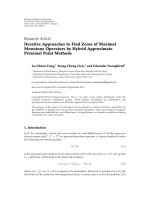
Fig. 1.1—American Specification for shear design (1920-
1951) based on ACI Standard No. 23, 1920.
445R-4 MANUAL OF CONCRETE PRACTICE
concrete cylinder strength. The concrete in the cracked web
of a beam is subjected to diagonal compressive stresses that
are parallel or nearly parallel to the inclined cracks. The
compressive strength of this concrete should be established
to prevent web-crushing failures. The strength of this con-
crete is a function of 1) the presence or absence of cracks and
the orientation of these cracks; 2) the tensile strain in the
trans-verse direction; and 3) the longitudinal strain in the
web. These limits are discussed in Chapters 2, 3, and 6.
The pioneering work from Ritter and Mörsch received
new impetus in the period from the 1960s to the 1980s, and
there-fore, in more recent design codes, modified truss mod-
els are used. Attention was focused on the truss model with
diagonals having a variable angle of inclination as a viable
model for shear and torsion in reinforced and prestressed
concrete beams (Kupfer 1964; Caflisch et al. 1971; Lampert
and Thurlimann 1971; Thurlimann et al. 1983). Further de-
velopment of plasticity theories extended the applicability of
the model to nonyielding domains (Nielsen and Braestrup
1975; Muller 1978; Marti 1980). Schlaich et al. (1987) ex-
tended the truss model for beams with uniformly inclined di-
agonals, all parts of the structure in the form of STM. This
approach is particularly relevant in regions where the distri-
bution of strains is significantly nonlinear along the depth.
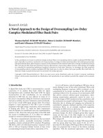
Schlaich et al. (1987) introduced the concept of D and B re-
gions, where D stands for discontinuity or disturbed, and B
stands for beam or Bernoulli. In D regions the distribution of
strains is nonlinear, whereas the distribution is linear in B re-
gions. A structural-concrete member can consist entirely of
a D region; however, more often D and B regions will exist
within the same member or structure [see Fig. 1.2, from
Schlaich et al. (1987)]. In this case, D regions extend a dis-
tance equal to the member depth away from any discontinu-
ity, such as a change in cross section or the presence of
concentrated loads. For typical slender members, the por-
tions of the structure or member between D regions are B re-
gions. The strut-and-tie approach is discussed in detail in
Chapter 6.
By analyzing a truss model consisting of linearly elastic
members and neglecting the concrete tensile strength,
Kupfer (1964) provided a solution for the inclination of the di-
agonal cracks. Collins and Mitchell (1980) abandoned the as-
sumption of linear elasticity and developed the compression
field theory (CFT) for members subjected to torsion and
shear. Based on extensive experimental investigation, Vec-
chio and Collins (1982, 1986) presented the modified com-
pression field theory (MCFT), which included a rationale for
determining the tensile stresses in the diagonally cracked con-
crete. Although the CFT works well with medium to high per-
centages of transverse reinforcement, the MCFT provides a
more realistic assessment for members having a wide range of
amounts of transverse reinforcement, including the case of no
web reinforcement. This approach is presented in Chapter 2.
Parallel to these developments of the truss model with vari-
able strut inclinations and the CFT, the 1980s also saw the fur-
ther development of shear friction theory (Chapter 5). In
addition, a general theory was developed for beams in shear
using constitutive laws for friction and by determining the
strains and deformations in the web. Because this approach
considers the discrete formation of cracks, the crack spacing
and crack width should be determined and equilibrium
checked along the crack to evaluate the crack-slip mechanism
of failure. This method is presented in Chapter 3. The topic of
members without transverse reinforcement is dealt with in
Chapter 4.
1.3—Overview of current ACI design procedures
The ACI 318M-95 sectional design approach for shear in
one-way flexural members is based on a parallel truss model
with 45 degree constant inclination diagonals supplemented
by an experimentally obtained concrete contribution. The
contribution from the shear reinforcement V
s
for the case of
vertical stirrups (as is most often used in North American
practice), can be derived from basic equilibrium consider-
ations on a 45 degree truss model with constant stirrup spac-
ing s, and effective depth d. The truss resistance is
supplemented with a concrete contribution V
c
for both rein-
forced and prestressed concrete beams. Appendix A presents
the more commonly used shear design equations for the con-
crete contribution in normalweight concrete beams, includ-
ing effects of axial loading and the contribution from vertical
stirrups V
s
.
Fig. 1.2—Frame structure containing substantial part of B regions, its statical system, and
bending moments (Schlaich et al. 1987).
RECENT APPROACHES TO SHEAR DESIGN OF STRUCTURAL CONCRETE 445R-5
1.4—Summary
ACI 318 procedures have evolved into restricted,
semiempirical approaches. The primary shortcomings of
ACI 318M-95 are the many empirical equations and rules
for special cases, and particularly the lack of a clear model
that can be extrapolated to cases not directly covered. This
situation would be improved if code approaches were based
on clear and transparent physical models. Several of such
models are discussed in subsequent chapters.
In Chapter 2, a sectional design approach using the MCFT
is described. Chapter 3 discusses other truss models incorpo-
rating a concrete contribution and provides a brief review of
some European code approaches.
The special case of members with no transverse shear re-
inforcement is addressed in Chapter 4. This chapter also pre-
sents an overview of the way the concrete contribution V
c
is
determined for beams. Chapter 5 presents a method of limit
analysis in the form of a shear-friction mechanism. In Chap-
ter 6, the generalized full member truss approach in the form
of strut-and-tie systems for one-way flexural members is il-
lustrated. Particular attention is given to the design approach
in B and D regions, including the detailing of reinforcement
ties, individual struts, and nodal zones.
The aim of this report is to describe these recent approaches
to shear design and point out their common roots and com-
plementary natures. This report does not endorse any given
approach but provides a synthesis of these truss model-based
approaches and related theories. The final goal of this report
is to answer the challenge posed by Committee 426 over 20
years ago.
CHAPTER 2—COMPRESSION FIELD
APPROACHES
2.1—Introduction
The cracked web of a reinforced concrete beam transmits
shear in a relatively complex manner. As the load is in-
creased, new cracks form while preexisting cracks spread
and change inclination. Because the section resists moment
as well as shear, the longitudinal strains and the crack incli-
nations vary over the depth of the beam (Fig. 2.1).
The early truss models of Ritter (1899) and Mörsch (1920,
1922) approximated this behavior by neglecting tensile
stresses in the diagonally cracked concrete and assuming that
the shear would be carried by diagonal compressive stresses
in the concrete inclined at 45 degree to the longitudinal axis.
The diagonal compressive concrete stresses push apart the
top and bottom faces of the beam, while the tensile stresses
in the stirrups pull them together. Equilibrium requires that
these two effects be equal. According to the 45 degree truss
model, the shear capacity is reached when the stirrups yield
and will correspond to a shear stress of
(2-1)
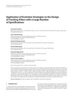
For the beam shown in Fig. 2.1, this equation would predict
a maximum shear stress of only 0.80 MPa. As the beam ac-
tually resisted a shear stress of about 2.38 MPa, it can be seen
that the 45 degree truss equation can be very conservative.
One reason why the 45 degree truss equation is often very
conservative is that the angle of inclination of the diagonal
compressive stresses measured from the longitudinal axis
θ is
typically less than 45 degrees. The general form of Eq. (2-1) is
(2-2)
With this equation, the strength of the beam shown in Fig. 2.1
could be explained if
θ was taken equal to 18.6 degrees.
Most of the inclined cracks shown in Fig. 2.1 are not this flat.
Before the general truss equation can be used to determine
the shear capacity of a given beam or to design the stirrups
to resist a given shear, it is necessary to know the angle
θ.
Discussing this problem, Mörsch (1922) stated, “it is abso-
lutely impossible to mathematically determine the slope of
the secondary inclined cracks according to which one can
v
A
v
f
y
b
w
s
ρ
v
f
y
==
v
ρ
v
f
y
θ
cot
=
Fig. 2.1—Example of cracked web of beam failing in shear.
445R-6 MANUAL OF CONCRETE PRACTICE
design the stirrups.” Just seven years after Mörsch made this
statement, another German engineer, H. A. Wagner (1929),
solved an analogous problem while dealing with the shear
design of “stressed-skin” aircraft. Wagner assumed that after
the thin metal skin buckled, it could continue to carry shear
by a field of diagonal tension, provided that it was stiffened
by transverse frames and longitudinal stringers. To deter-
mine the angle of inclination of the diagonal tension, Wagner
considered the deformations of the system. He assumed that
the angle of inclination of the diagonal tensile stresses in the
buckled thin metal skin would coincide with the angle of in-
clination of the principal tensile strain as determined from
the deformations of the skin, the transverse frames, and the
longitudinal stringers. This approach became known as the
tension field theory.
Shear design procedures for reinforced concrete that, like
the tension field theory, determine the angle
θ by considering
the deformations of the transverse reinforcement, the longitu-
dinal reinforcement, and the diagonally stressed concrete have
become known as compression field approaches. With these
methods, equilibrium conditions, compatibility conditions,
and stress-strain relationships for both the reinforcement and
the diagonally cracked concrete are used to predict the load-
deformation response of a section subjected to shear.
Kupfer (1964) and Baumann (1972) presented approaches
for determining the angle
θ assuming that the cracked con-
crete and the reinforcement were linearly elastic. Methods
for determining
θ applicable over the full loading range and
based on Wagner’s procedure were developed by Collins
and Mitchell (1974) for members in torsion and were applied
to shear design by Collins (1978). This procedure was
known as CFT.
2.2—Compression field theory
Figure 2.2 summarizes the basic relationships of the CFT.
The shear stress v applied to the cracked reinforced concrete
causes tensile stresses in the longitudinal reinforcement f
sx
and the transverse reinforcement f
sy
and a compressive stress
in the cracked concrete f
2
inclined at angle θ to the longitu-
dinal axis. The equilibrium relationships between these
stresses can be derived from Fig. 2.2 (a) and (b) as
(2-3)
(2-4)
(2-5)
where
ρ
x
and ρ
v
are the reinforcement ratios in the longitu-
dinal and transverse directions.
If the longitudinal reinforcement elongates by a strain of
ε
x
, the transverse reinforcement elongates by ε
y
, and the di-
agonally compressed concrete shortens by
ε
2
, then the direc-
tion of principal compressive strain can be found from
Wagner’s (1929) equation, which can be derived from Mo-
hr’s circle of strain (Fig. 2.2(d)) as
(2-6)
Before this equation can be used to determine
θ, however,
stress-strain relationships for the reinforcement and the con-
crete are required. It is assumed that the reinforcement
strains are related to the reinforcement stresses by the usual
simple bilinear approximations shown in Fig. 2.2(e) and (f).
Thus, after the transverse strain
ε
y
exceeds the yield strain of
the stirrups, the stress in the stirrups is assumed to equal the
yield stress f
y
, and Eq. (2-3) becomes identical to Eq. (2-2).
Based on the results from a series of intensively instru-
mented beams, Collins (1978) suggested that the relationship
between the principal compressive stress f
2
and the principal
ρ
v
f
sy
f
cy
v
θ
tan
==
ρ
x
f
sx
f
cx
v
θ
cot
==
f
2
v
θ
tan
θ
cot
+
()
=
θ
2
tan
ε
x
ε
2
+
ε
y
ε
2
+
=
Fig. 2.2—Compression field theory (Mitchell and Collins
1974).
RECENT APPROACHES TO SHEAR DESIGN OF STRUCTURAL CONCRETE 445R-7
compressive strain ε
2
for diagonally cracked concrete would
differ from the usual compressive stress-strain curve derived
from a cylinder test (Fig 2.2(g)). He postulated that as the
strain circle becomes larger, the compressive stress required
to fail the concrete f
2max
becomes smaller (Fig. 2.2(h)). The
relationships proposed were
(2-7)
where
γ
m
= diameter of the strain circle (that is, ε
1
+ ε
2
); and
ε′
c
= strain at which the concrete in a cylinder test reaches
the peak stress f
′
c
.
For values of f
2
less than f
2max
(2-8)
It was suggested that the diagonally cracked concrete fails at
a low compressive stress because this stress must be transmit-
ted across relatively wide cracks. If the initial cracks shown
in Fig. 2.2(a) formed at 45 degrees to the longitudinal rein-
forcement, and if
θ is less than 45 degrees, which will be the
case if
ρ
v
is less than ρ
x
, then significant shear stresses should
be transmitted across these initial cracks (Fig. 2.2(b)). The
ability of the concrete to transmit shear across cracks de-
pends on the width of the cracks, which, in turn, is related to
the tensile straining of the concrete. The principal tensile
strain
ε
1
can be derived from Fig. 2.2(d) as
(2-9)
For shear stresses less than that causing first yield of the
reinforcement, a simple expression for the angle
θ can be de-
rived by rearranging the previous equations to give
(2-10)
where
n = modular ratio E
s
/E
c
; and
E
c
is taken as f
c
′/ε′
c
.
For the member shown in Fig. 2.1,
ρ
x
is 0.0303, ρ
v
is
0.00154, and n = 6.93; therefore, Eq. (2-10) would give a
θ
value of 26.4 degrees. This would imply that the stirrups
would yield at a shear stress of 1.62 MPa.
After the stirrups have yielded, the shear stress can still be
increased if
θ can be reduced. Reducing θ will increase the
tensile stress in the longitudinal reinforcement and the com-
pressive stress in the concrete. Failure will be predicted to
occur either when the longitudinal steel yields or when the
concrete fails. For the member shown in Fig. 2.1, failure of
the concrete is predicted to occur when
θ is lowered to 15.5
degrees, at which stage the shear stress is 2.89 MPa and
ε
x
is
1.73
× 10
–3
. Note that these predicted values are for a section
where the moment is zero. Moment will increase the longi-
tudinal tensile strain
ε
x
, which will reduce the shear capacity.
For example, if
ε
x
was increased to 2.5 × 10
–3
, concrete fail-
ure would be predicted to occur when
θ is 16.7 degrees and
the shear stress is 2.68 MPa.
2.3—Stress-strain relationships for diagonally
cracked concrete
Since the CFT was published, a large amount of experimen-
tal research aimed at determining the stress-strain characteris-
tics of diagonally cracked concrete has been conducted. This
work has typically involved subjecting reinforced concrete
elements to uniform membrane stresses in special-purpose
testing machines. Significant experimental studies have
been conducted by Aoyagi and Yamada (1983), Vecchio and
Collins (1986), Kollegger and Mehlhorn (1988), Schlaich et
al. (1987), Kirschner and Collins (1986), Bhide and Collins
(1989), Shirai and Noguchi (1989), Collins and Porasz
(1989), Stevens et al. (1991), Belarbi and Hsu (1991), Marti
and Meyboom (1992), Vecchio et al. (1994), Pang and Hsu
(1995), and Zhang (1995). A summary of the results of many
of these studies is given by Vecchio and Collins (1993).
These experimental studies provide strong evidence that
the ability of diagonally cracked concrete to resist compres-
sion decreases as the amount of tensile straining increases
(Fig. 2.3). Vecchio and Collins (1986) suggested that the
maximum compressive stress f
2max
that the concrete can re-
sist reduces as the average principal tensile strain
ε
1
increases
in the following manner
(2-11)
The Norwegian concrete code (1989) recommended a simi-
lar relationship except the coefficient of 170 was reduced to
100. Belarbi and Hsu (1995) suggested
(2-12)
The various relationships for the reduction in compressive
strength are compared with the experimental results from 73 el-
ement tests in Fig. 2.3. It can be seen that Eq. (2-11) lies near the
middle of the data scatter band. For larger strains, Eq. (2-12)
gives higher values to better fit some data at strains of up to 4%.
The compression field approach requires the calculation of
the compressive strain in the concrete
ε
2
associated with the
compressive stress f
2
[Eq. (2-6)]. For this purpose, Vecchio
and Collins (1986) suggested the following simple stress-
strain relationship
(2-13)
where f
2max
is given by Eq. (2-11).
f
2max
3.6
f
c
′
12γ
m
ε′
c
⁄+
=
ε
2
f
2
f
c
′ε′
c
=
ε
1
ε
x
ε
x
ε
2
+
()θ
2
cot+=
θ
4
tan1
1
nρ
x
+
1
1
nρ
v
+
⁄=
f
2max
f
c
′
0.8170ε
1
+
f
c
′≤=
f
2max
0.9
f
c
′
1400ε
1
+
=
f
2
f
2max
2
ε
2
ε′
c
ε
2
ε′
c
2
–=
445R-8 MANUAL OF CONCRETE PRACTICE
Somewhat more complex expressions relating f
2
and ε
2
were suggested by Belarbi and Hsu (1995). They are
(2-14a)
(2-14b)
where, for “proportional loading”
(2-14c)
and for “sequential loading”
(2-14d)
As the cracked web of a reinforced concrete beam is sub-
jected to increasing shear forces, both the principal compres-
sive strain
ε
2
and the principal tensile strain ε
1
are increased.
Before yield of the reinforcement, the ratio
ε
1
/ε
2
remains
reasonably constant. Figure 2.4(a) shows that the compres-
sive stress–compressive strain relationships predicted by
Eq. (2-13) and (2-14) for the case where the ratio
ε
1
/ε
2
is held
constant at a value of 5 are similar. Figure 2.4(b) compares
the relationship for the less realistic situation of holding
ε
1
constant while increasing ε
2
. The predicted stress-strain re-
lationships depend on the sequence of loading. Once again,
the predictions of Eq. (2-13) and (2-14) are very similar.
f
2
ζ
σ0
f
c
′ 2
ε
2
ζ
ε0
ε′
c
ε
2
ζ
ε0
ε′
c
2
– if
ε
2
ζ
ε0
ε′
c
1≤=
f
2
ζ
σ0
f
c
′ 1
ε
2
ζ
ε0
ε′
c
1
–
⁄
2 ζ⁄
ε0
1–
2
– if
ε
2
ζ
ε0
ε′
c
1>=
ζ
α0
0.9
1400ε
1
+
and ζ
ε0
1
1500ε
1
+
==
ζ
α0
0.9
1250ε
1
+
and ζ
ε0
1==
Fig. 2.3—Maximum concrete compressive stress as function of principal tensile strain.
Fig. 2.4—Compressive stress-compressive strain relation-
ships for diagonally cracked concrete: (a) proportion load-
ing,
ε
1
and ε
2
increased simultaneously; and (b) sequential
loading
ε
1
applied first then ε
2
increased.
RECENT APPROACHES TO SHEAR DESIGN OF STRUCTURAL CONCRETE 445R-9
For typical reinforced concrete beams, the percentage of
longitudinal reinforcement
ρ
x
will greatly exceed the per-
centage of stirrup reinforcement
ρ
v
. In this situation there
will be a substantial reduction in the inclination
θ of the prin-
cipal compressive stresses after cracking. Figure 2.5 shows
the observed crack patterns for a reinforced concrete element
that contained reinforcement only in the direction of tension
(x-direction) and was loaded in combined tension and shear.
The first cracks formed at about 71 degrees to the x-axis.
These initial cracks were quite narrow and remained reason-
ably constant in width throughout the test. As the load was
increased, new cracks formed in directions closer to the rein-
forcement direction, and the width of these new cracks in-
creased gradually. Failure was characterized by the rapid
widening of the cracks that formed at about 33 degrees to the
x-axis. For this extreme case, the direction of principal stress
in the concrete differed by up to 20 degrees from the direc-
tion of principal strain (Bhide and Collins 1989). The pre-
dicted angle, based on Wagner’s assumption that the
principal stress direction coincides with the principal strain
direction, lay about halfway between the observed strain di-
rection and the observed stress direction. For elements with
both longitudinal and transverse reinforcement, the direc-
tions of principal stress in the concrete typically deviated by
less than 10 degrees from the directions of the principal
strain (Vecchio and Collins 1986). Based on these results, it
was concluded that determining the inclination of the princi-
pal stresses in the cracked concrete by Wagner’s equation
was a reasonable simplification.
The CFT assumes that after cracking there will be no tensile
stresses in the concrete. Tests on reinforced concrete ele-
ments, such as that shown in Fig. 2.5, demonstrated that even
after extensive cracking, tensile stresses still existed in the
cracked concrete and that these stresses significantly in-
creased the ability of the cracked concrete to resist shear
stresses. It was found (Vecchio and Collins 1986, Belarbi and
Hsu 1994) that after cracking the average principal tensile
stress in the concrete decreases as the principal tensile strain
increases. Collins and Mitchell (1991) suggest that a suitable
relationship is
(2-15)
while Belarbi and Hsu (1994) suggest
(2-16)
Equation (2-16) predicts a faster decay for f
1
with increas-
ing
ε
1
than does Eq. (2-15). For example, for a 35 MPa con-
crete and an
ε
1
value of 5 × 10
–3
, Eq. (2-15) would predict an
average tensile stress of 0.76 MPa, whereas Eq. (2-16) would
predict 0.35 MPa.
2.4—Modified compression field theory
The MCFT (Vecchio and Collins 1986) is a further devel-
opment of the CFT that accounts for the influence of the ten-
sile stresses in the cracked concrete. It is recognized that the
local stresses in both the concrete and the reinforcement vary
from point to point in the cracked concrete, with high rein-
forcement stresses but low concrete tensile stresses occurring
at crack locations. In establishing the angle
θ from Wagner’s
equation, Eq. (2-6), the compatibility conditions relating the
strains in the cracked concrete to the strains in the reinforce-
ment are expressed in terms of average strains, where the
strains are measured over base lengths that are greater than
the crack spacing (Fig. 2.2(c) and (d)). In a similar manner,
the equilibrium conditions, which relate the concrete stresses
and the reinforcement stresses to the applied loads, are ex-
pressed in terms of average stresses; that is, stresses aver-
aged over a length greater than the crack spacing. These
relationships can be derived from Fig. 2.6(a) and (b) as
f
1
0.33 f
c
′
1500ε
1
+
(MPa) units=
f
1
0.31f
c
′
12500ε
1
,
()
0.4
(MPa) units=
Fig. 2.5—Change of inclination of crack direction with increase in load.
445R-10 MANUAL OF CONCRETE PRACTICE
(2-17)
(2-18)
(2-19)
These equilibrium equations, the compatibility relationships
from Fig. 2.2(d), the reinforcement stress-strain relationships
from Fig. 2.2(e) and (f), and the stress-strain relationships for
the cracked concrete in compression (Eq. (2-13)) and tension
(Fig. 2.6(e)) enable the average stresses, the average strains,
and the angle
θ to be determined for any load level up to the
failure.
Failure of the reinforced concrete element may be gov-
erned not by average stresses, but rather by local stresses that
occur at a crack. In checking the conditions at a crack, the ac-
tual complex crack pattern is idealized as a series of parallel
cracks, all occurring at angle
θ to the longitudinal reinforce-
ment and space a distance s
θ
apart. From Fig. 2.6(c) and (d),
the reinforcement stresses at a crack can be determined as
ρ
v
f
sy
f
cy
v
θ
f
1
–
tan
==
ρ
x
f
sx
f
cx
v
θ
f
1
–
cot
==
f
2
v
θ
tan
θ
cot
+
()
f
1
–=
(2-20)
(2-21)
It can be seen that the shear stress v
ci
on the crack face re-
duces the stress in the transverse reinforcement but increases
the stress in the longitudinal reinforcement. The maximum
possible value of v
ci
is taken (Bhide and Collins 1989) to be
related to the crack width w and the maximum aggregate size
a by the relationship illustrated in Fig. 2.6(f) and given by
(2-22)
The crack width w is taken as the crack spacing times the
principal tensile strain
ε
1
. At high loads, the average strain in
the stirrups
ε
y
will typically exceed the yield strain of the re-
inforcement. In this situation, both f
sy
in Eq. (2-17) and f
sycr
in Eq. (2-20) will equal the yield stress in the stirrups. Equat-
ing the right-hand sides of these two equations and substitut-
ing for v
ci
from Eq. (2-22) gives
(2-23)
Limiting the average principal tensile stress in the concrete
in this manner accounts for the possibility of failure of the
aggregate interlock mechanisms, which are responsible for
transmitting the interface shear stress v
ci
across the crack
surfaces.
Figure 2.7 illustrates the influence of the tensile stresses in
the cracked concrete on the predicted shear capacity of two se-
ries of reinforced concrete elements. In this figure, RA-STM
stands for rotating-angle softened-truss model. If tensile
stresses in the cracked concrete are ignored, as is done in the
CFT, elements with no stirrups (
ρ
v
= 0) are predicted to have
no shear strength. When these tensile stresses are accounted
for, as is done in the MCFT, even members with no stirrups
ρ
v
f
syer
v
θ
tan
v
ci
θ
tan
–=
ρ
x
f
sxer
v
θ
cot
v
ci
θ
cot
–=
v
ci
0.18 f
c
′≤ 0.3
24w
a 16
+
+
⁄ (MPa, mm)
f
1
0.18 f
c
′θtan0.3
24w
a 16
+
+
⁄≤
Fig. 2.6—Aspects of modified compression field theory.
Fig. 2.7—Comparison of predicted shear strengths of two
series of reinforced concrete elements.
RECENT APPROACHES TO SHEAR DESIGN OF STRUCTURAL CONCRETE 445R-11
are predicted to have significant postcracking shear
strengths. Figure 2.7 shows that predicted shear strengths are
a function not only of the amount of stirrup reinforcement,
but also of the amount of longitudinal reinforcement. In-
creasing the amount of longitudinal reinforcement increases
the shear capacity. Increasing the amount of longitudinal re-
inforcement also increases the difference between the CFT
prediction and the MCFT prediction. For the elements with
2% of longitudinal reinforcement and with
ρ
v
f
y
/f ′
c
greater
than about 0.10, yielding of the longitudinal reinforcement at
a crack (Eq. (2-21)) limits the maximum shear capacity. In
this situation, the influence of the tensile stresses in the
cracked concrete on the predicted shear strength is negligibly
small. On the other hand, when the total longitudinal rein-
forcement is 10% of the web area, this longitudinal rein-
forcement remains well below yield stress, and the failure,
for larger amounts of stirrups, is then governed by crushing
of the concrete. The tensile stresses in the cracked concrete
stiffen the element, reduce the concrete strains, and make it
possible to resist larger shear stresses before failure. The pre-
dicted shear strength of elements that contain relatively
small amounts of stirrups are influenced by the spacing of
the diagonal cracks s
θ
. If this spacing is increased, the crack
width, w, associated with a given value of
ε
1
increases, and
the tension transmitted through the cracked concrete de-
creases (Eq. (2-23)). This aspect of behavior is illustrated in
Fig. 2.8, which compares the shear capacities predicted by
the MCFT for two series of elements. In one series, the crack
spacing is taken as 300 mm, whereas in the other, it is taken
as 2000 mm. It is assumed that the amount of longitudinal re-
inforcement and the axial loading of the elements is such that
the longitudinal strain,
εx, is held constant at 0.5 × 10
-3
. It can
be seen that the predicted shear capacity becomes more sen-
sitive to crack spacing as the amount of stirrup reinforcement,
ρ
v
, is reduced. When ρ
v
is zero, the element with a 2000 mm
crack spacing is predicted to have only about half the shear ca-
pacity of the element with a 300 mm crack spacing.
2.5—Rotating-angle softened-truss model
A somewhat different procedure to account for tensile
stresses in diagonally cracked concrete has been developed by
Hsu and his coworkers at the University of Houston (Belarbi
and Hsu 1991, 1994, 1995; Pang and Hsu 1995; Hsu 1993).
This procedure is called the rotating-angle softened-truss
model (RA-STM). Like the MCFT, this method assumes that
the inclination of the principal stress direction
θ in the cracked
concrete coincides with the principal strain direction. For typ-
ical elements, this angle will decrease as the shear is in-
creased, hence the name rotating angle. Pang and Hsu (1995)
limit the applicability of the rotating-angle model to cases
where the rotating angle does not deviate from the fixed an-
gle by more than 12 degrees. Outside this range, they recom-
mend the use of a fixed-angle model, which is discussed in
Section 3.5.
The method formulates equilibrium equations in terms of
average stresses (Fig. 2.6(b)) and compatibility equations in
terms of average strains (Fig. 2.2(d)). The softened stress-
strain relationship of Eq. (2-14) is used to relate the principal
compressive stress in the concrete f
2
to the principal compres-
sive strain
ε
2
, whereas Eq. (2-16) is used to relate the average
tensile stress in the concrete f
1
to the principal tensile strain ε
1
.
Instead of checking the stress conditions at a crack, as is
done by the MCFT, the RA-STM adjusts the average stress–
average strain relationships of the reinforcement to account
for the possibility of local yielding at the crack. The relation-
ships suggested are
Fig. 2.8—Influence of crack spacing on predicted shear capacity.
445R-12 MANUAL OF CONCRETE PRACTICE
(2-24a)
(2-24b)
(2-24c)
(2-24d)
f
s
E
s
ε
s
if
ε
s
ε
n
≤
=
f
s
f
y
0.912B–()0.020.25B+
()
+
E
s
f
y
ε
s
=
1
2
α
2
45
⁄
–
1000ρ
– if ε
s
ε
n
>
ε
n
f
y
E
s
0.932B–()1
2
α
2
45
⁄
–
1000ρ
–=
B
f
cr
fy
1.5
ρ⁄=
where
ρ = reinforcement ratio; and
α
2
= angle between the initial crack direction and the longi-
tudinal reinforcement.
The resulting relationships for a case where the longitudinal
reinforcement ratio is 0.02 and the transverse reinforcement
ratio is 0.005 are illustrated in Fig. 2.9.
Figure 2.7 shows the shear strength-predictions for the
RA-STM for the two series of reinforced concrete ele-
ments. Although the MCFT and the RA-STM give similar
predictions for low amounts of reinforcement, the predict-
ed strengths using the RA-STM are somewhat lower than
those given by the MCFT for elements with higher amounts
of reinforcement.
Both the MCFT and the RA-STM are capable of predicting
not only the failure load but also the mode of failure. Thus, as
shown in Fig. 2.10, a reinforced concrete element loaded in
pure shear can fail in four possible modes. Both the longitudi-
nal and transverse reinforcement can yield at failure (Mode 1),
only the longitudinal reinforcement yields at failure (Mode 2),
only the transverse reinforcement yields at failure (Mode 3),
or neither reinforcement yields at failure (Mode 4).
2.6—Design procedure based on modified
compression field theory
The relationships of the MCFT can be used to predict the
shear strength of a beam such as that shown in Fig. 2.11. As-
suming that the shear stress in the web is equal to the shear
force divided by the effective shear area b
w
d
v
, and that, at
failure, the stirrups will yield, equilibrium equations (2-17)
can be rearranged to give the following expression for the
shear strength V
n
of the section
(2-25a)
(2-25b)
(2-25c)
V
n
V
c
V
s
V
p
++=
V
n
f
1
b
w
d
v
θcot
A
v
f
y
s
d
v
θcot V
p
++=
V
n
β f
c
′ b
w
d
v
A
v
f
y
s
d
v
+ θcot V
p
+=
Fig. 2.9—Average-reinforcement-stress/average-reinforcement-strain relationships used
in rotating-angle softened-truss model.
Fig. 2.10—Four failure modes predicted by rotating-angle
softened-truss model for element loaded in pure shear
(adapted from Pang and Hsu 1995).
RECENT APPROACHES TO SHEAR DESIGN OF STRUCTURAL CONCRETE 445R-13
where
V
c
= shear strength provided by tensile stresses in the
cracked concrete;
V
s
= shear strength provided by tensile stresses in the stir-
rups;
V
p
= vertical component of the tension in inclined pre-
stressing tendon;
b
w
= effective web width, taken as the minimum web
width within the shear depth;
d
v
; d
v
= effective shear depth, taken as the flexural lever
arm, but which need not be taken less than 0.9d; and
β = concrete tensile stress factor indicating the ability of
diagonally cracked concrete to resist shear.
The shear stress that the web of a beam can resist is a func-
tion of the longitudinal straining in the web. The larger this
longitudinal straining becomes, the smaller the shear stress
required to fail the web. In determining the shear capacity of
the beam, it is conservative to use the highest longitudinal
strain
ε
x
occurring within the web. For design calculations,
ε
x
can be approximated as the strain in the tension chord of
the equivalent truss. Therefore
(2-26)
but need not be taken greater than 0.002, where
f
po
= stress in the tendon when the surrounding concrete is
at zero stress, which may be taken as 1.1 times the ef-
fective stress in the prestressing f
se
after all losses;
A
s
= area of nonprestressed longitudinal reinforcement on
the flexural tension side of the member;
A
ps
= area of prestressed longitudinal reinforcement on the
flexural tension side of the member;
M
u
= moment at the section, taken as positive; and
N
u
= axial load at the section, taken as positive if tensile
and negative if compressive.
The determination of
ε
x
for a nonprestressed beam is illus-
trated in Fig. 2.12.
The longitudinal strain parameter,
ε
x
, accounts for the in-
fluence of moment, axial load, prestressing, and amount of
longitudinal reinforcement on the shear strength of a section.
If
ε
x
and the crack spacing s
θ
are known, the shear capacity
corresponding to a given quantity of stirrups can be calculated
(Fig. 2.8). This is equivalent to finding the values of
β and θ
in Eq. (2-25).
Values of
β and θ determined from the modified compres-
sion field theory (Vecchio and Collins 1986) and suitable for
members with at least minimum web reinforcement are given
in Fig. 2.13. In determining these values, it was assumed that
the amount and spacing of the stirrups would limit the crack
spacing to about 300 mm. The
θ values given in Fig. 2.13 en-
sure that the tensile strain in the stirrups,
ε
v
, is at least equal
to 0.002 and that the compressive stress, f
2
, in the concrete
does not exceed the crushing strength f
2max
. Within the
range of values of
θ that satisfy these requirements, the values
given in Fig. 2.13 result in close to the smallest amount of to-
tal shear reinforcement being required to resist a given shear.
ε
x
M
u
d
v
⁄
()
0.5
N
u
0.5
V
u
θ
cot
A
ps
f
po
–++
E
s
A
s
E
p
A
ps
+
=
Fig. 2.11—Beam subjected to shear, moment, and axial load.
445R-14 MANUAL OF CONCRETE PRACTICE
2.6.1 Minimum shear reinforcement—A minimum amount
of shear reinforcement is required to control diagonal crack-
ing and provide some ductility. In ACI 318M-95, this
amount is specified as
(2-27)
The AASHTO specifications (1994) relate the minimum
reinforcement required to the concrete strength and require a
larger quantity of stirrups for high-strength concrete. The
AASHTO specifications require that
(2-28)
This type of relationship was found to give reasonable esti-
mates compared with experiments conducted by Yoon et al.
(1996). There is some concern, however, that the equation
may not be conservative enough for large reinforced concrete
members that contain low percentages of longitudinal rein-
forcement (ASCE-ACI 426 1973).
2.6.2 Example: Determine stirrup spacing in reinforced
concrete beam—To illustrate the method, it will be used to de-
termine the stirrup spacing at Section B for the member tested
as shown in Fig. 2.1, which will result in a predicted shear
strength of 580 kN with a capacity-reduction factor of 1.0
From Eq. (2-26)
A
v
f
y
b
w
s
0.33 MPa>
A
v
f
y
b
w
s
0.083 f
c
′ MPa>
v
u
f
c
′
V
u
b
w
d
v
f
c
′
580000,
2950.9× 920× 75×
0.032===
ε
x
M
u
d
v
⁄
()
0.5
V
u
θ
cot
+
E
s
A
s
=
Figure 2.13 shows that if v
u
/ f ′
c
is less than 0.05 and ε
x
is be-
tween 1.5
× 10
-3
and 2 × 10
-3
, θ is about 42 degrees. With this
value of
θ, the calculated value of ε
x
is 1.67 × 10
-3
and β is
approximately 0.155, according to Fig. 2.13. Equation (2-25)
then becomes
which gives a required stirrup spacing of 381 mm. Note that
because the tested beam contained stirrups at a spacing of
440 mm, the design method is a little conservative.
2.6.3 Example: Determine stirrup spacing in a prestressed
concrete beam—If the member had also contained a straight
post-tensioned tendon near the bottom face consisting of six
13 mm strands with an effective stress of 1080 MPa, the cal-
culations for the required stirrup spacing would change in
the following manner. Equation (2-26) becomes
ε
x
580000
,
1300828
⁄
×
()
0.5580000
θ
cot
,
×
+
20000047003300×
+
×
()
,
=
ε
x
1.2310
3–
0.32910
3–
θcot×+×=
580000, 0.15575295828
200522
×
s
+
××=
828
×
42 degrees
cot
ε
x
{
[
580000
,
1300828
⁄
×
()
0.5580000
θ
cot
,
×
+
×
Fig. 2.12—Determination of strains, ε
x
, for nonprestressed
beam.
Fig. 2.13—Values of
β and θ for members containing at
least the minimum amount of stirrups.
RECENT APPROACHES TO SHEAR DESIGN OF STRUCTURAL CONCRETE 445R-15
Figure 2.13 shows that if v
u
/f ′
c
is less than 0.05 and ε
x
is
approximately 0.75
× 10
-3
, θ is about 33 degrees. With this
value of
θ, the calculated value of ε
x
is 0.76 × 10
-3
. For this
value of
ε
x
, the value of β is approximately 0.155, according
to Fig. 2.13. Equation (2-25) then becomes
which gives a required stirrup spacing of 848 mm.
Stirrups spaced at 848 mm in the member shown in Fig. 2.1
would not provide adequate crack control, and the assump-
tion that the crack spacing was about 300 mm would no longer
be valid. The AASHTO specifications (1994) require that
the stirrup spacing not exceed 0.8d
v
or 600 mm.
6
–
991.11080
]
×
×
×⁄
20000047003300699
×
+
×
+
×
()
,
[]
}
580000, 0.2075295828
200522
×
s
+××=
82833 degrees
cot
×
To satisfy the minimum stirrup amount requirement of
Eq. (2-28), the stirrup spacing for the beam shown in Fig. 2.1
should be
2.6.4 Design of member without stirrups—For members
without stirrups or with less than the minimum amount of
stirrups, the diagonal cracks will typically be more widely
spaced than 300 mm. For these members, the diagonal
cracks will become more widely spaced as the inclination of
the cracks
θ is reduced (Fig. 2.5 and 2.14). The crack spacing
when
θ equals 90 degrees is called s
x
, and this spacing is pri-
marily a function of the maximum distance between the lon-
gitudinal reinforcing bars (Fig. 2.14). As shown in Fig. 2.5
the values of
β and θ for members with less than the mini-
mum amount of stirrups depend on the longitudinal strain
parameter,
ε
x
, and the crack spacing parameter, s
x
, where s
x
need not be taken as greater than 2000 mm. As s
x
increases,
β decreases, and the predicted shear strength decreases.
The
β and θ values given in Fig. 2.15 were calculated as-
suming that the maximum aggregate size a is 19 mm. The
values can be used for other aggregate sizes by using an
equivalent crack spacing parameter
(2-29)
s
200522
×
2950.08375×
492 mm=<
s
xe
s
x
35
a 16
+
=
Fig. 2.14—Influence of reinforcement on spacing of diago-
nal cracks.
Fig. 2.15—Values of
β and θ for members containing less
than the minimum amount of stirrups.
445R-16 MANUAL OF CONCRETE PRACTICE
If the member shown in Fig. 2.1 did not contain any stir-
rups, the shear strength at Section B could be predicted from
Fig. 2.15 in the following manner. As the longitudinal bars
are spaced 195 mm apart and the maximum aggregate size is
10 mm, the crack spacing parameter is
If
ε
x
is estimated to be 1.0 × 10
-3
, then from Fig. 2.15, θ is
about 41 degrees and
β is about 0.18. Equation (2-25) then
gives
whereas Eq. (2-26) gives
Using the calculated value of
ε
x
of 1.10 × 10
–3
, β would be
about 0.17, and a more accurate estimate of the failure shear
would be 360 kN.
If the member did not contain the six 20 mm diameter skin-
reinforcement bars, the crack spacing parameter would in-
crease to
s
xe
195
35
1016
+
263 mm==
V
n
0.1875295× 828381 kN=×=
ε
x
381000
,
1300828
⁄
×
()
0.538100041 degreecot
,
×
+
20000047003300×
+
×
()
,
=
1.1010
3
–
×
=
s
xe
828
35
1016+
1115 mm==
If
ε
x
is estimated to be 0.75 × 10
–3
, then from Fig. 2.15, θ is
about 55.5 degrees and
β is about 0.13. With these values, V
n
would be reduced to 275 kN and ε
x
would be calculated as
0.71
× 10
–3
. A second iteration would give the predicted
shear strength as 283 kN.
2.6.5 Additional design considerations—In the design ap-
proach based on the MCFT, the stirrups required at a partic-
ular section can be determined from Eq. (2-25) as
(2-30)
given the shear, moment, and axial load acting at the section.
Although this calculation is performed for a particular section,
shear failure caused by yielding of the stirrups involves yield-
ing this reinforcement over a length of beam of about d
v
cot θ.
Therefore, a calculation for one section can be taken as rep-
resenting a length of beam d
v
cot θ long with the calculated
section being in the middle of this length. Near a support, the
first section checked is the section 0.5d
v
cot θ from the face
of the support. In addition, near concentrated loads, sections
closer than 0.5d
v
cot θ to the load need not be checked. As a
simplification, the term 0.5d
v
cot θ may be approximated as
d
v
. The required amount of stirrups at other locations along
the length of the beam can be determined by calculating sec-
tions at about every tenth point along the span, until it is ev-
ident that shear is no longer critical.
Shear causes tensile stresses in the longitudinal reinforce-
ment as well as in the stirrups (Eq. (2-21)). If a member con-
tains an insufficient amount of longitudinal reinforcement,
its shear strength may be limited by yielding of this rein-
forcement. To avoid this type of failure, the longitudinal re-
inforcement on the flexural tension side of the member
should satisfy the following requirement
(2-31)
Figure 2.16 illustrates the influence of shear on the tensile
force required in the longitudinal reinforcement. Whereas
the moment is zero at the simple support, there still needs to
be considerable tension in the longitudinal reinforcement
near this support. The required tension T at a simple support
can be determined from the free-body diagram in Fig. 2.16 as
(2-32)
but
(2-33)
V
s
V
u
φ
V
c
– V
p
–≥
A
s
f
y
A
ps
f
ps
M
φd
v
0.5
N
u
φ
+≥+
V
u
φ
0.5V
s
– V
p
–
θcot+
T
V
u
φ
0.5V
s
– V
p
–
θcot=
T 0.5
V
u
φ
V
p
–
θcot≥
Fig. 2.16—Influence of shear on tension in longitudinal
reinforcement.
RECENT APPROACHES TO SHEAR DESIGN OF STRUCTURAL CONCRETE 445R-17
The reinforcement provided at the support should be detailed
in such a manner that this tension force can be safely resisted
and that premature anchorage failures do not occur.
At the maximum moment locations shown in Fig. 2.16, the
shear force changes sign, causing fanning of the diagonal
compressive stresses as
θ passes through 90 degrees. See
also Fig. 2.1. Because of this, the maximum tension in these
regions need not be taken as larger than that required for the
maximum moment. The traditional North American proce-
dure for accounting for the influence of shear on the longitu-
dinal reinforcement involves extending the longitudinal
reinforcement a distance d beyond the point at which it is no
longer required to resist flexure, in addition to other detailing
requirements. As can be seen from Fig. 2.16, the require-
ments of Eq. (2-31) can be satisfied in a conservative manner
by simply extending the longitudinal reinforcement a dis-
tance d
v
cot θ past the point at which it is no longer required
for flexure alone.
For sections at least a distance d
v
away from the maximum
moment locations, the MCFT predicts that increasing the
moment decreases the shear strength, while increasing the
shear decreases the flexural strength. This point is illustrated
in Fig. 2.17, which gives the shear-moment interaction dia-
gram for Section B of the beam described in Fig. 2.1. The
shear-failure line shown in this figure was determined by cal-
culating V from Eq. (2-25) with the
β and θ values corre-
sponding to chosen values of
ε
x
and then using Eq. (2-26) to
determine the corresponding values of M. The flexural-fail-
ure line, which corresponds to yielding of the longitudinal
steel, was determined from Eq. (2-31) with
φ taken as unity.
A shear-moment interaction diagram, such as that shown in
Fig. 2.17, can be used to determine the predicted failure load
of a section when it is subjected to a particular loading ratio.
Section B of the beam shown in Fig. 2.1 is loaded such that
the moment-to-shear ratio equals 1.3 m (that is, M/Vd = 1.41).
At this loading ratio, the section is predicted to fail in shear
with yielding of the stirrups and slipping of the cracks when
the shear reaches a value of 552 kN. For this beam, the ex-
perimentally determined failure shear was about 5% higher
than this value.
CHAPTER 3—TRUSS APPROACHES WITH
CONCRETE CONTRIBUTION
3.1—Introduction
The traditional truss model assumes that the compression
struts are parallel to the direction of cracking and that no
stresses are transferred across the cracks. This approach has
been shown to yield conservative results when compared with
test evidence. More recent theories consider one or both of the
following two resisting mechanisms: 1) tensile stresses in
concrete that exist transverse to the struts; or 2) shear stresses
that are transferred across the inclined cracks by aggregate
interlock or friction. Both mechanisms are interrelated and
result in: 1) the angle of the principal compression stress in the
web being less than the crack angle; and 2) a vertical compo-
nent of the force along the crack that contributes to the shear
strength of the member. The resisting mechanisms give rise to
V
c
, the concrete contribution. These theories typically assume
that there is no transfer of tension across cracks.
In this chapter, several approaches incorporating the so-
called concrete contribution are discussed, which begin with
the assumptions for the angle and the spacing of the inclined
Fig. 2.17—Shear-moment interaction diagram for rectangular section.
445R-18 MANUAL OF CONCRETE PRACTICE
cracks. Then, the principal tensile strain, ε
1
, in the web and
the widths of the inclined cracks are calculated, as in the
MCFT, discussed in Chapter 2. The stress transfer across the
cracks can then be determined, giving V
c
. The state of stress
in the web results in tensile stress in the web perpendicular to
the principal compressive stresses.
This chapter also contains a brief review of the recent
European codes EC2, Part 1 (1991) and CEB-FIP Model
Code 1990 (1993), which are based on related approaches.
3.2—Overview of recent European codes
The strut-and-tie model approaches have influenced re-
cent European codes including, to a lesser extent, EC2, Part
1 (1991) and, to a larger extent, CEB-FIP Model Code 1990
(1993). EC2, Part 1 is primarily based on the previous CEB-
FIP Model Code 1978, although the design clauses contain
several changes. The static or lower-bound approach of the
theory of plasticity may be used in the design. Appropriate
measures should be taken to ensure ductile behavior (EC2,
Part 1, Section 2.5.3.6.3). Corbels, deep beams, and anchor-
age zones for post-tensioning forces (EC2, Part 1, Section
2.5.3.7) may be analyzed, designed, and detailed in accor-
dance with lower-bound plastic solutions. In this approach,
the average design compressive stress may be taken as vf
cd
with v = 0.60 and f
cd
= f
ck
/1.5 the factored design strength
(with f
ck
= 0.9f ′
c
for a concrete of about 28 MPa, the value
of 0.60f
cd
corresponds to about 0.54f ′
c
/1.5 = 0.36f ′
c
). The
m aximum strength to be used in axial compression is 0.85f
cd
,
including an allowance for sustained load.
The shear design expressions use three different values for
shear resistance: V
Rd1
, V
Rd2
, and V
Rd3
. The shear resistance
V
Rd1
is for members without shear reinforcement and is
based on an empirical formula. This formula incorporates
the influence of concrete strength, reinforcing ratio, member
depth, and axial forces.
The resistance V
Rd2
is the upper limit of the shear strength
intended to prevent web-crushing failures. The limiting value
is a function of: 1) the inclination and spacing of the cracks;
2) the tensile strain in the transverse reinforcement; and 3)
the longitudinal strain in the web. The limiting value of the
shear strength is calculated using an effective diagonal stress
in the struts f
dmax
= (νf
cd
). As a simplification, the effective-
ness factor
ν in EC2, Part 1 is given by the expression
(3-1)
with f
ck
(MPa) as the characteristic cylinder strength (ap-
proximately 0.9f
′
c
). The stress in the inclined struts is calcu-
lated from equilibrium as
(3-2)
The resistance V
Rd3
, provided by the shear reinforcement,
may be determined from two alternative design methods—
the standard method or the variable-angle truss method. The
standard method is similar to the current U.S. design prac-
tice where a concrete contribution is added to that of the
shear reinforcement
(3-3)
The concrete contribution V
cd
is assumed equal to V
Rd1
, the
shear resistance of members without shear reinforcement.
The resistance of the vertical shear reinforcement is given by
(3-4)
based on a flexural lever arm of 0.9d between the truss
chords (d = effective depth).
The variable-angle truss method uses a truss with struts in-
clined at an angle
θ. The strength provided by the shear rein-
forcement for beams with transverse stirrups follows from
the vertical equilibrium
(3-5)
where
A
v
= area of the transverse stirrups at spacing s;
f
yv
= yield strength of the shear reinforcement;
0.9d = flexural lever arm or effective truss depth; and
θ = angle of inclined struts.
The theory of plasticity assumes that the capacity of the
web is achieved by reaching simultaneously the yielding of
the shear reinforcement and the limiting stress, f
d
, in the in-
clined struts (web crushing), Eq. (3-2). This assumption
yields a condition for the angle
θ of the inclined struts and a
function for the capacity depending on the amount of shear
reinforcement. This function may be plotted in a dimension-
less format, and it appears as a quarter circle (Fig. 3.1). This
figure shows that, for given amounts of transverse reinforce-
ment, much larger capacities are predicted than those based
on the traditional Mörsch model, which assumes a strut incli-
nation
θ = 45 degrees. For very low amounts of transverse re-
inforcement, very flat angles
θ are predicted so that mostly
lower limits are given to avoid under-reinforced members.
For comparison, Fig. 3.1 also shows the predictions using
Eq. (3-3) according to the standard method of EC2. Accord-
ing to EC2, Section 4.3.2.4.4, the angle
θ in Eq. (3-5) may be
varied between:
• -0.4 < cot
θ < 2.5 for beams with constant longitudinal
reinforcement; and
• -0.5 < cot
θ < 2.0 for beams with curtailed longitudinal
reinforcement
There are different interpretations of these limits. For ex-
ample, in Germany, the minimum inclination was increased
to cot
θ = 1.75 for reinforced concrete members. For mem-
bers subjected also to axial forces, the following value is
suggested
(3-6)
ν
0.70
f
ck
200
⁄
–=
f
d
V
u
b
v
⁄
d
v
θ
cos
θ
sin=
V
Rd3
V
cd
V
wd
+=
V
wd
A
v
f
y
0.9
ds
⁄
=
V
Rd3
V
s
A
v
s
⁄
()
f
yv
0.9
d
θ
cot==
θ
cot1.253
σ
cp
f
cd
⁄
–
()
=
RECENT APPROACHES TO SHEAR DESIGN OF STRUCTURAL CONCRETE 445R-19
with σ
cp
= axial stress in middle of web. In the presence of
axial tension, larger strut angles are required, and the limits
of EC2 are considered unsafe.
The provisions for member design have been based on
strut-and-tie models instead of a separate sectional design for
the different effects of bending, axial load, shear, and torsion.
The shear design is based on the theory of plasticity using the
variable-angle truss method. The strut angle may be assumed
as low as about 18 degrees, corresponding to cot
θ = 3.
CEB-FIP Model Code 1990 (1993) limits the compressive
stress in the struts in a form similar to that given by Eq. (3-1).
In EC2, Part 1 (1991), minimum reinforcement amounts
are required in beams for the longitudinal reinforcement as
well as for the shear reinforcement. The latter is made depen-
dent on the concrete class and the steel class, and, for exam-
ple, amounts to a minimum required percentage of shear
reinforcement, min
ρ
v
= 0.0011 for steel with f
y
= 500 MPa
and medium concrete strengths between f
′
c
= 23 and 33 MPa.
For higher concrete strengths, the value is increased to min
ρ
v
= 0.0013. For slabs, no minimum transverse reinforce-
ment is required.
CEB-FIP Model Code 1990 requires a minimum longitu-
dinal reinforcement in the tension zone of 0.15%. The re-
quired minimum amount for the shear reinforcement in webs
of beams is expressed in terms of a mechanical reinforcing
ratio rather than a geometrical value min
ρ
v
. The requirement
is min
ωv = ρ
v
f
y
/f
ctm
= 0.20. This correctly expresses that,
for higher concrete strengths (that is, higher values of aver-
age tensile strengths f
ctm
), more minimum transverse rein-
forcement is required. In terms of min
ρ
v
, this means about
0.090% for concrete having a compressive strength of about
22 MPa, 0.14% for concrete with 41 MPa compressive
strength, and 0.20% for 67 MPa concrete.
3.3—Modified sectional-truss model approach
In the so-called “modified sectional-truss model” ap-
proach (CEB-FIP 1978; EC2 1991; Ramirez and Breen
1991) the nominal shear strength of nonprestressed or pre-
stressed concrete beams with shear reinforcement is V
n
= V
c
+ V
s
, where V
c
represents an additional concrete contribution
as a function of the shear stress level, and V
s
= strength pro-
vided by the shear reinforcement.
For nonprestressed concrete beams, the additional con-
crete contribution V
c
has been suggested (Ramirez and
Breen 1991) as
(3-7)
where
v
cr
= shear stress resulting in the first diagonal tension
cracking in the concrete; and
v = shear stress level due to factored loads.
For prestressed concrete beams (Ramirez and Breen
1991), the additional concrete contribution takes the form of
V
c
1
2
3
ν
cr
ν–
()
b
w
d=
(3-8)
with f
′
c
in MPa, where K = the factor representing the bene-
ficial effect of the prestress force on the concrete diagonal
tensile strength and further capacity after cracking. The ex-
pression for the K factor can be derived from a Mohr circle
analysis of an element at the neutral axis of a prestressed
concrete beam before cracking and is
(3-9)
where
f
t
= principal diagonal tension stress; and
f
pc
= normal stress at the neutral axis.
This expression is the same one used in ACI 318M-95 as the
basis for the web cracking criteria V
cw
. The factor K is usu-
ally limited to 2.0, and is set equal to 1.0 in those sections of
the member where the ultimate flexural stress in the extreme
tension fiber exceeds the concrete flexural tensile strength.
This limitation is similar to the provision in 318M-95 that
limits the concrete contribution to the smaller of the two
values, V
cw
and V
ci
.
The strength provided by the shear reinforcement, V
s
, for
beams with vertical stirrups represents the truss capacity in
shear derived from the equilibrium condition by summing
the vertical forces on an inclined crack free-body diagram.
The resulting expression is given in Eq. (3-5). According to
Ramirez and Breen (1991), the lower limit of angle of incli-
nation
θ for the truss diagonals is 30 degrees for nonpre-
stressed concrete and 25 degrees for prestressed beams.
The additional longitudinal tension force due to shear can
be determined from equilibrium conditions of the truss mod-
el as V
u
cot θ, where V
u
= factored shear force at the section.
Because the shear stresses are assumed uniformly distributed
over the depth of the web, this force acts as the section mid-
depth; thus, it may be resisted by equal additional tension
forces acting at the top and bottom longitudinal truss chords,
V
c
K
f
c
′
6
b
w
0.9d=
K 1
f
pc
f
t
+
0.5
=
Fig. 3.1—Calculated shear strength as function of θ and
shear reinforcement index (
ρ
v
= A
v
/ b
w
s).
445R-20 MANUAL OF CONCRETE PRACTICE
with each force being equal to 0.5V cot θ. In this approach, a
limit of 2.5
√f ′
c
(MPa) has also been proposed (Ramirez and
Breen 1991) that represents the diagonal compressive
strength as a function of the shear that can be carried along
the diagonal crack surface. The diagonal compression stress
can be calculated from equilibrium and geometry consider-
ations in the diagonally cracked web, resulting in an expres-
sion similar to Eq. (3-2).
The term V
c
is reflected in the design of the stirrup rein-
forcement, but it does not affect dimensioning of the longi-
tudinal reinforcement or the check of diagonal compressive
stresses. This is justified by the fact that experimental obser-
vations have shown that dimensioning of the shear reinforce-
ment (stirrups) based entirely on the equilibrium conditions
of the parallel chord truss model described in this section un-
duly penalizes the majority of members that are subjected to
low levels of shear stress or that have no or low amounts of
shear reinforcement. A similar effect on the longitudinal re-
inforcement, however, has not been fully verified. The fact
that there are relatively few large-scale specimens, that most
tests consist of beams with continuous longitudinal rein-
forcement, and that almost all of the test beams are simply
supported under a point load would seem to justify a simple
expression for the required amount of longitudinal reinforce-
ment at this time. The check of diagonal compressive stress-
es is a conservative check on the maximum shear force that
can be carried by the reinforced concrete member without a
web-crushing failure.
3.4—Truss models with crack friction
3.4.1 Equilibrium of truss models with crack friction—The
truss model with crack friction starts with basic assumptions
for the spacing and shape of cracks in a B region of a struc-
tural-concrete member subjected to shear. It is assumed that
forces are transferred across the cracks by friction, which de-
pends on the crack displacements (slips and crack widths);
therefore, the strains in the member have to be calculated.
This approach was developed for the shear design of webs by
several researchers, including Gambarova (1979), Dei Poli et al.
(1987, 1990), Kupfer et al. (1979, 1983), Kirmair (1987),
Kupfer and Bulicek (1991), and Reineck (1990, 1991a).
The approach uses the free-body diagram in Fig. 3.2,
which is obtained by separating the member along an in-
clined crack in the B region of a structural-concrete member
with transverse reinforcement. Vertical equilibrium of this
body gives the basic equation
(3-10)
where
V
n
= total shear resisted (nominal shear strength);
V
s
= shear force carried by the stirrups;
V
c
= sum of the vertical components of the tangential fric-
tion forces at the crack T
f
, and the normal force at the
crack N
f
(see Fig. 3.2(b)); and
V
p
= vertical component of force in prestressing tendon.
The dowel force of the longitudinal reinforcement, which
has a role in members without transverse reinforcement, is
neglected (see Fig. 3.2). Furthermore, the chords are as-
sumed to be parallel to the axis of the member so that there
is no vertical component of an inclined compression chord of
the truss. Leonhardt (1965, 1977), Mallee (1981), and Park
and Paulay (1975) have proposed truss models with inclined
chords, but these models are more complicated. For a non-
prestressed concrete member of constant depth, Eq. (3-10)
simplifies to
(3-11)
The shear force component carried by all the stirrups cross-
ing the crack is
(3-12)
where
β
cr
= crack inclination;
d
v
= inner level arm; and
s = stirrup spacing.
V
n
V
s
V
c
V
P
++=
V
n
V
s
V
c
+=
V
s
A
v
f
y
d
v
β
cr
cot
s
=
Fig. 3.2—Free-body diagram of B region at end support and forces at crack due to friction: (a) free-body diagram of end sup-
port region; and (b) forces due to friction (Leonhardt 1995; Reineck 1991a).
RECENT APPROACHES TO SHEAR DESIGN OF STRUCTURAL CONCRETE 445R-21
The force, V
f
, is the vertical component of the combined
friction forces, T
f
and N
f
, across the inclined crack in the
web, as shown in Fig. 3.2(b). The tangential force T
f
has two
components: T
fo
, the tangential force that may be resisted
with N
f
equal to zero; and T
fσ
, the additional tangential force
due to N
f
. Equation (3-11) shows that the shear force compo-
nent, V
f
, due to friction is additive with the shear force car-
ried by the stirrups. This is also the case for all design
methods with a concrete contribution such as ACI 318M-95
or EC2 with either the standard method (Section 3.2) or the
modified truss model approach (Section 3.3). So far, the con-
crete contribution has mainly been justified empirically, but
Eq. (3-11) offers a clear physical explanation for the V
c
term;
that is, that it is the shear force component, V
f
, transferred by
friction across the cracks.
3.4.2 Inclination and spacing of inclined cracks—In the use
of the truss model with crack friction, a necessary condition
is that the crack inclination and the crack spacing should be
assumed or determined by nonlinear analysis. The angle of
the inclined cracks is normally assumed at 45 degrees for
nonprestressed concrete members. Kupfer et al. (1983) has
pointed out that this angle could be up to 5 degrees flatter, be-
cause of a reduction of Young’s modulus caused by microc-
racking. Flatter angles will appear for prestressed concrete
members or for members with axial compression, and steeper
angles will occur for members with axial tension. For such
members, the angle of the principal compressive stress at the
neutral axis of the uncracked state is commonly assumed as
the crack angle (Loov and Patniak 1994).
The spacing of the inclined cracks is primarily determined
by the amount and spacing of reinforcement, and relevant for-
mulas have been proposed by Gambarova (1979), Kupfer and
Moosecker (1979), Kirmair (1987), and Dei Poli et al. (1990).
3.4.3 Constitutive laws for crack friction—The truss mod-
el with crack friction requires constitutive laws for the trans-
fer of forces across cracks by friction or interface shear.
Before 1973, this shear transfer mechanism was known and
clearly defined by the works of Paulay and Fenwick, Taylor,
and others (see Section 4.3.3), but only a few tests and no
theories were available for formulating reliable constitutive
laws. This has changed considerably in the last 20 years due
to the work of Hamadi (1976), Walraven (1980), Walraven
and Reinhardt (1981), Gambarova (1981), Daschner and
Kupfer (1982), Hsu et al. (1987), Nissen (1987), and Tassios
and Vintzeleou (1987). An extensive state-of-the-art report
on interface shear was recently presented by Gambarova and
Prisco (1991).
The constitutive law proposed by Walraven (1980) has of-
ten been used by others because it describes not only the
shear stress-slip relation for different crack widths but also
the associated normal stresses. It was based on a physical
model for the contact areas between crack surfaces, and the
proposed laws were corroborated with tests on concrete with
normal as well as lightweight aggregates (see Section 4.3.3).
3.4.4 Determining shear resistance V
f
=V
c
due to crack
friction—The shear force component V
f
= V
c
in Eq. (3-10)
and (3-11) transferred by friction across the cracks depends
on the available slip and on the crack width, requiring that
the strains in the chords and in the web be determined. In ad-
dition, the displacements and the strains should be compati-
ble with the forces in the model according to the constitutive
laws for the shear force components. Often the capacity of
the crack friction mechanism is reached before crushing of
the concrete struts between the cracks. Figure 3.3 gives the
results of different calculations of the shear force component
V
f
= V
c
in terms of stress from Dei Poli et al. (1987) and
Kupfer and Bulicek (1991), but similar results have been ob-
tained by Leonhardt (1965) and Reineck (1990, 1991a). The
shear stress, v
c
, in Fig. 3.3 depends on the magnitude of the
shear, the strains of the struts and stirrups on the longitudinal
strain
ε
x
in the middle of the web, and on the crack spacing.
The results in Fig. 3.3 support the notion that, for a wide
range of applications and for code purposes, a constant value
Fig. 3.3—Shear force carried by crack friction versus ulti-
mate shear force plotted in a dimensionless diagram.
Fig. 3.4—Design diagram with simplified shear force com-
ponent V
f
due to friction, proposed by Reineck (3.14, 3.15).
445R-22 MANUAL OF CONCRETE PRACTICE
of the concrete contribution may be assumed. The practical
result for the shear design is the dimension-free design dia-
gram shown in Fig. 3.4, which is well known and used in
many codes (see also Fig. 3.1). Crack friction governs the de-
sign for low and medium shear. For very high shear, the
strength of the compression struts governs, which is charac-
terized by the quarter circle in Fig. 3.4, as explained in Fig.
3.1. The crack friction approach considers the influence of ax-
ial forces (tension and compression) as well as prestress, as
shown in Fig. 3.5. For a member with axial tension (Fig.
3.5(a)), steeper inclined cracks occur in the web and the term
V
c
is reduced so that more transverse reinforcement is re-
quired in comparison with a member without axial forces
(Fig. 3.4). The opposite is the case for prestressed members
or members with axial compression (Fig. 3.5(b)); the cracks
are flatter, so that less transverse reinforcement is required
than for a member without axial force (Fig. 3.4), although the
term V
c
is reduced and may even disappear.
3.4.5 Stresses and strength of concrete between cracks—
The main function of the concrete between the cracks is to
act as the struts of a truss formed together with the stirrups as
described by Mörsch (1920, 1922) (see Fig. 3.6(a)). The
additional friction forces acting on the crack surfaces result
in a biaxial state of stress with a principal compression field
at a flatter inclination than the crack angle
β
cr
.
The minor principal stress is tensile for small shear forces
so the state of stress may be visualized by the two trusses
shown in Fig. 3.7. The usual truss model with uniaxial com-
pression inclined at the angle
θ in Fig. 3.7(a) is superimposed
on a truss with concrete tension ties perpendicular to the
struts (Fig. 3.7(b)). Thus, there are two load paths for the
shear transfer, as defined by Schlaich et al. (1987) and as ear-
lier shown by Reineck (1982), and with different explana-
tions by Lipski (1971, 1972) and Vecchio and Collins (1986)
in their MCFT. The model in Fig. 3.7(b) is the same as that
Fig. 3.5—Simplified design diagram for members subjected to shear and axial forces as
proposed by Reineck (1991).
Fig. 3.6—Forces and stress fields in discrete concrete struts between cracks (Kupfer et al.
1983; Reineck 1991a).
Fig. 3.7—Smeared truss-models corresponding to principal
struts between cracks as proposed by Reineck (1991a): (a)
truss with uniaxial compression field; and (b) truss with
biaxial tension-compression field.
RECENT APPROACHES TO SHEAR DESIGN OF STRUCTURAL CONCRETE 445R-23
proposed by Reineck (1989; 1991a,b) for members without
transverse reinforcement, so that the transition from mem-
bers with to members without transverse reinforcement is
consistently covered.
For high shear forces, the minor principal stress is compres-
sive. These compressive stresses are so small, however, that
they are usually neglected, and only the truss of Fig. 3.7(a)
remains with a uniaxial compression field. This is the model
used in the theory of plasticity.
The concrete between the cracks is uncracked and forms
the strut. Apart from the compressive stresses due to the truss
action, however, there is also transverse tension in the struts
due to the friction stresses and forces induced by the bonded
stirrups. This reduces the strength below that allowed in
compression chords. Further reasons for such a reduction are
also the smaller effective width of the strut (rough crack sur-
faces) and the disturbances by the crossing stirrups. Schlaich
and Schafer (1983), Eibl and Neuroth (1988), Kollegger/Me-
hlhorn (1990), and Schafer et al. (1990) reached the conclu-
sions that the effective concrete strength of the struts could
be assumed as
(3-13)
This is a relatively high value compared to those dis-
cussed in Chapters 2 and 6 and the so-called “effective
strengths” of, for example, 0.60f
ck
= 0.54f ′
c
or 0.50f
ck
=
0.45f
′
c
used in the theory of plasticity. The results of the
higher value for compressive strength is that, for high ratios
of transverse reinforcement, excessively high shear capac-
ities may be predicted.
3.5—Fixed-angle softened-truss models
Hsu and his colleagues have proposed two different soft-
ened-truss models to predict the response of membrane ele-
ments subjected to shear and normal stress (Pang and Hsu
1992, 1996; Zhang 1995). The rotating angle softened-truss
model considers the reorientation of the crack direction that
f
dmax
0.80
f
ck
0.72
f
c
′
==
Fig. 3.8—Reinforced concrete membrane elements subjected to in-plane stresses.
445R-24 MANUAL OF CONCRETE PRACTICE
occurs as the loads are increased from initial cracking up to
failure (see Fig. 3.8(g)). This first model has been discussed in
Chapter 2. The second model, known as the fixed-angle soft-
ened-truss model, assumes that the concrete struts remain par-
allel to the initial cracks. This initial crack direction depends
on the principal concrete stress directions just before cracking
(see Fig. 3.8(f)). With the terms defined as in Fig. 3.8, the
equilibrium and compatibility equations for this fixed-angle
softened-truss model are as follows
• Equilibrium equations
(3-14)
(3-15)
(3-16)
where
σ
c
2
, σ
c
1
= average normal stresses of concrete in Directions
2 and 1, respectively;
τ
c
21
= average shear stress of concrete in 2-1 coordi-
nate; and
φ = angle of inclined cracks.
[In the following equations, the symbol
φ is kept, following
previous works by Pang and Hsu (1992, 1996) and Zhang
(1995);
φ actually is the same as β
cr
in this chapter.]
• Compatibility equations
(3-17a)
(3-17b)
(3-18)
where
ε
1
, ε
2
= average normal strain of element in Directions 2
and 1, respectively; and
γ
21
= average shear strain of element in 2-1 coordinate.
Because Eq. (3-14) to (3-18) are based on the 2-1 coordi-
nate, they include the terms for shear stress,
τ
c
21
,
and shear
strain,
γ
21
, of cracked concrete. After cracking, the principal
compressive stress direction in the concrete struts will typical-
ly not coincide with the crack direction; that is,
θ ≠ φ. This cor-
responds to the concept of friction across the cracks as
discussed in Section 3.4. In applying these equations, the
stresses are determined from the strains using the constitutive
laws shown in Fig. 3.9. An efficient algorithm for the solu-
σ
l
σ
2
c
φ
2
cosσ
1
c
φ
2
sinτ
21
c
2 φφρ
l
f
l
+cossin++=
σ
t
σ
2
c
φ
2
sinσ
1
c
φ
2
cosτ
21
c
2 φφρ
t
f
t
+cossin–+=
τ
lt
σ–
2
c
σ
1
c
+()φφτ
21
c
φ
2
cosφ
2
sin–
()
+cossin=
ε
l
ε
2
φ
2
cosε
1
φ
2
sinγ
21
φsinφcos++=
ε
t
ε
2
φ
2
sinε
1
φ
2
cosγ
21
φsinφcos–+=
γ
lt
2 ε
2
– ε
1
+()φsinφcosγ
21
φ
2
cosφ
2
sin–
()
+=
Fig. 3.9—Constitutive laws of concrete and steel: (a) softened stress-strain curve of concrete in compression; (b) average
stress-strain curve of concrete in tension; (c) average stress-strain curve of steel bars in concrete; (d) average stress-strain
curve of concrete in shear.
RECENT APPROACHES TO SHEAR DESIGN OF STRUCTURAL CONCRETE 445R-25
tion of the equations in the fixed-angle softened-truss model
has been developed (Zhang 1995).
The shear yield strength of a membrane element has been
derived from the fixed-angle softened truss model (Pang and
Hsu 1996) to be
(3-19)
The right-hand side of Eq. (3-19) consists of two terms: the
first term is the contribution of concrete, V
c
, attributable to
τ
c
21
the shear stress of cracked concrete in the 2-1 coordinate;
and the second term is the contribution of steel V
s
.
3.6—Summary
Shear design codes require a simple means of computing
a realistic V
c
term. This so-called concrete contribution is
important in the design of beams where the factored shear
force is near the value of the shear force required to produce
diagonal tension cracking. This term is necessary for the eco-
nomic design of beams and slabs with little or no shear rein-
forcement.
In this chapter, several truss model approaches incorporat-
ing a concrete contribution term have been discussed. The
implementation of this philosophy in recent European codes
has also been illustrated. In this chapter, a physical explana-
tion is given of the concrete contribution term, V
c
, in the
form of the vertical component of the forces transferred
across the inclined cracks. This crack leads to a sliding fail-
ure through the compression strut. In other approaches, this
phenomenon is accounted for by permissible stresses for the
struts, that is, reduction factors, v, as explained, for example,
in Section 3.2.
The approaches discussed in this chapter as well as the
MCFT in Chapter 2 describe the structural behavior of
beams under increasing load. This behavior cannot be cov-
ered by the truss model alone. Furthermore, the truss model
with crack friction discussed in Section 3.4 can be extended
to regions of geometrical discontinuities (D regions). In
those regions, the formation of a single crack indicating a
failure surface is very likely. Common examples are beams
with openings, dapped end-supports, frame corners, and cor-
bels (Marti 1991). In all of these cases, a crack will start from
the corner, and a premature failure may occur before the steel
yields.
The fixed-angle softened-truss model proposed by Hsu and
his colleagues assumes that the initial crack direction remains
unchanged. The orientation of these initial cracks is dictated
by the orientation of principal stresses just prior to cracking.
After cracking, shear stresses due to friction develop in these
cracks so that the principal compressive stress direction is not
the same as the crack direction. Such was the case also in the
truss model with crack friction approach. The fixed-angle
method also results in a concrete contribution term.
τ
lt
τ
21
c
()
2
2 ρ
l
f
ly
y
ρ
t
f
ty
ρ
l
f
ly
ρ
t
f
ty
+=
CHAPTER 4—MEMBERS WITHOUT TRANSVERSE
REINFORCEMENT
4.1—Introduction
Structural-concrete members with sufficient reinforce-
ment in both directions (longitudinal and transverse) can be
designed using the simple strut-and-tie models described in
Chapter 6 or the theories described in Chapters 2 and 3.
Many structural-concrete members are constructed without
transverse reinforcement (that is, no stirrups or bent-up
bars), such as slabs, footings, joists, and lightly stressed
members. The application of a simple strut-and-tie model, as
shown in Fig. 4.1, may result in an unsafe solution. Assum-
ing that the shear in this slender member without transverse
reinforcement is carried by a flat compression strut predicts
that failure will be due to yielding of the longitudinal rein-
forcement, whereas in reality, a brittle shear failure occurred
due a diagonal crack.
The 1973 ASCE-ACI Committee 426 report gave a detailed
explanation of the behavior of beams without transverse rein-
forcement, including the different shear-transfer mechanisms
and failure modes. The main parameters influencing shear
failure were discussed, and numerous empirical formulas
were given. These equations continue to be the basis of shear
design rules in many building codes around the world.
The main goal of this chapter is to review design models and
analytical methods for structural-concrete members without
transverse reinforcement in light of new developments that
have occurred since the early 1970s. Only the two-dimensional
problem of shear in one-way members is considered. Punching
shear, which is a complex three-dimensional problem, is not
discussed here; however, it should be noted that an important
reason for the continued research on structural-concrete
beams without transverse reinforcement is the development of
more rational methods for punching shear. Information on
punching shear can be found in the CEB state-of-the-art report
prepared by Regan and Braestrup (1985).
4.2—Empirical methods
The simplest approach, and the first to be proposed (Mörsch
1909), is to relate the average shear stress at failure to the
concrete tensile strength. This empirical approach is presented
first because it forms the basis of ACI 318M-95 and several
other codes of practice. Experimental results have shown
that the average principal tensile stress to cause secondary
diagonal cracking (that is, flexure-shear cracking) is usual-
ly much less than concrete tensile strength. One reason is
the stress concentration that occurs at the tip of initial
cracks. Another factor is the reduction in cracking stress due
Fig. 4.1—Crack pattern at shear failure of beam with unsafe
strut-and-tie model (Kupfer and Gerstle 1973).