guide for the use of volumetric-measuring and continuous-mixing concrete equipment (reapproved 1997)
Bạn đang xem bản rút gọn của tài liệu. Xem và tải ngay bản đầy đủ của tài liệu tại đây (733.11 KB, 14 trang )
304.6R-91
Guide for the Use of
Volumetric-Measuring
and
Continuous-Mixing Concrete Equipment (Reapproved 1997)
reported by ACI Committee 304
Arthur C. Cheff
Thomas R. Clapp*
James L. Cope
Wayne J. Costa
Henri Jean
DeCarbonel
Robert M. Eshbach
James R. Florey
Clifford Gordon
This guide includes a short history of and information on the basic
design and operation of equipment used to produce concrete by vol-
umetric measurement and continuous mixing (VMCM), frequently
called mobile mixers. Definitions, applications, and quality assur-
ance testing are discussed. The use of this equipment is compared to
weigh-batch-mix equipment for some of the limited differences.
Keywords:
admixtures; aggregates;
batching;
calibrating;
cements; cold weather
construction; colored concrete; concrete construction; field tests; fresh con-
cretes; grout; hot weather construction; material handling; measurement; mix-
ing; mixing plants; mixing time; mix proportioning; polymer concrete: precast
concrete; process control; production methods; shotcrete; slump; transit mix-
ers.
CONTENTS
Chapter 1 -Introduction
1.l General
1.2-Discussion
1.3-History
Chapter 2-Equipment
2. l-Materials storage and measurement
2.2-Mixers
2.3-Equipment condition
Chapter 3-Operations
3.1-General
3.2-Production rates
3.3-Planning
Gary R. Mass
Kurt R.
Melby
Richard W. Narva
John
H.
Skinner, III
Paul R.
Stodola*+
William X. Sypher
Louis L.
Szilandi
Robert E.
Tobin
Francis C. Wilson
James S. Pierce
Chairman
Donald E. Graham
Neil R. Guptill
Terence C. Holland*
James Hubbard
Thomas A. Johnson
Robert A. Kelsey
John C. King
William C.
Krell
3.4-Materials
3.5-Personnel qualifications
Chapter 4-Applications
4. l-General
4.2-Mixtures with short working times
4.3-Low-slump mixtures
4.4-Long unloading times
4.5-Concrete
at remote sites
4.6-Making small deliveries
4.7-Precast operations
4.8-Hot weather concreting
4.9-Mining
applications
4.10-Grouting and pile filling
4.1l-Colored concretes
4.12-Emergency applications
Chapter 5-Quality control and testing
5.1
-
General
5.2
-Calibration
5.3-Production testing
Chapter 6-Operational precautions
6.1-General
6.2-Cold weather concrete
6.3-Hot weather concrete
6.4-Aggregate moisture
6.5-Rapid slump loss
6.6-Use of admixtures
6.7-Fresh concrete properties
ACI
Committee Reports, Guides, Standard Practices, and
Commentaries are intended for guidance in designing, plan-
ning, executing, or inspecting construction and in preparing
specifications. Reference to these documents shall not be made
in the Project Documents. If items found in these documents
are desired to be part of the Project Documents they should
be phrased in mandatory language and incorporated into the
Project Documents.
*The
committee recognizes the special contributions of Paul Stodola, Thomas
Clapp, and Terry Holland.
chairman of Committee 304 since March 1989.
AC1
304.6R-91
became
effective
May 1, 1991.
Copyright
0
1991, American Concrete Institute.
All rights reserved including rights of reproduction and use in any form or
by any means, including the making of copies by any photo process, or by any
electronic or mechanical device, printed, written, or oral, or recording for sound
or visual reproduction or for use in any knowledge or retrieval system or de-
vice, unless permission in writing is obtained from the copyright proprietors.
304.6R-1
304.6R-2
MANUAL OF CONCRETE PRACTICE
Chapter 7-References
7.1-Specified and/or recommended references
7.2-Cited references
Appendix A-New York State DOT calibration
method
CHAPTER 1 -INTRODUCTION
1.1-General
The purpose of this document is to offer guidance on
volumetric-measurement and continuous-mixing
(VMCM) concrete production. It contains background
information on this method and items to be considered
when using it. A discussion of other types of continu-
ous-measurement equipment (i.e., conveyor belt scales
or weigh-in-motion scales) is outside the scope of this
report.
1.2-Discussion
The title uses the words “volumetric measuring” and
“continuous mixing.” The significance of these words
in the context of this guide are discussed in the follow-
ing paragraphs.
Volumetric measurement-When the ingredients of
concrete are flowing continuously and measured by
volume, by using a calibrated rotary opening, a cali-
brated fixed-gate opening, or a combination of these,
so that a known, predetermined volume of each ingre-
dient is obtained in a designated time interval, the
method of measurement is volumetric. Continuous vol-
umetric measurement with multiple ingredients requires
that the proper relationship among those ingredients be
maintained.
Continuous
mixing
-When the output of the mixer is
equivalent to the input of materials and the mixer can
be operated without interruption to charge or discharge
material, the mixer can be considered continuous. The
mixer may be started and stopped as required to meet
production requirements (provided that material input
is also started and stopped). Such a mixer is suitable for
both continuous or intermittent operation.
1.3-History
Volumetric measurement and continuous mixing
have a long history of producing concrete. For many
years the concept of “one shovel of cement, two shov-
els of sand, and three shovels of stone” was used to
produce concrete. Patents on continuous mixers date
back at least to 1913. It was not until these two tech-
nologies were successfully combined in the early 1960s
that general field use of this type of equipment began.
The first commercial unit was delivered in 1964. Be-
cause of the detail of original patents, there was only
one manufacturer of VMCM units until the early
198Os,
when other manufacturers began to offer this type of
equipment for concrete production.
By the
mid-1970s,
there were over 4000 VMCM ma-
chines in operation in the U.S. Generally, they were
used to produce small volumes of concrete. During the
late 1970s and early 198Os
,
specialty concretes needed
for bridge-deck renovation and highway repair, which
were difficult to produce in conventional transit mix-
ers, were being produced successfully by VMCM
equipment. This application gave the equipment cre-
dence and showed it could produce close-tolerance,
high-quality concrete consistently. VMCM equipment
has been considered by some people to be limited to
producing special mixtures or small volumes; however,
VMCM may be suitable for almost any concrete re-
quirement .
Standards activities related to concrete produced by
VMCM equipment have been limited. However, in 1971
ASTM developed and now maintains ASTM C 685,
“Standard Specification for Concrete Made by Volu-
metric Batching and Continuous Mixing.”
CHAPTER 2-EQUIPMENT
2.1-Materials storage and measurement
Measurement of material by volume can be accom-
plished by a variety of means. Rotary vane feeders
(both horizontal and vertical axis), screw conveyors
(both adjustable and fixed speed), drag chains, cali-
brated gate openings, variable-volume sliding compart-
ments, and vibrating plate feeders all have been used to
measure quantities of dry ingredients. Liquids may be
introduced by air pressure, pumps, or cylinders with the
flow controlled by valves or timers and measured by
flow meters. Readers are directed to the documents
produced by the equipment manufacturers for operat-
ing details of the various types of equipment. Cement,
water, and admixtures are stored in separate containers
and measured separately. Fine and coarse aggregates
are stored either separately or combined. If aggregates
are stored and used in a combined state, they must be
accurately preblended, and particular care must be
taken to avoid segregation.
In presently available equipment, a meter records the
rate of introduction of cement into the mixture and this
rate serves, directly or indirectly, to control the rate at
which other ingredients are added. All systems are in-
terconnected so that, once they are calibrated and set to
produce a specific concrete mixture, all ingredients are
simultaneously and continuously measured into the
mixer. This interconnecting allows either continuous or
intermittent operation of the system to accommodate
the quantities of the concrete needed. These intercon-
nections should not be confused with the interlocks
typically found in weigh-type batch plants. VMCM
equipment is designed to allow the relative proportions
of ingredients to be changed rapidly to vary the con-
crete mixture as required. Because the mixing chamber
only holds about 2
ft’,
such changes can be made with
little or no waste.
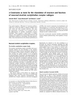
Typical VMCM units carry enough materials to pro-
duce 6 to 10
yd3
of concrete (Fig. 2.1). This limitation
is based upon axle loading limitations. Production of
larger volumes of concrete or high rates of production
will require special provisions for recharging the mate-
rial storage compartments.
CONTINUOUS MIXING EQUIPMENT
304.6R-3
crete
on the mixer-auger surfaces. Belts must be prop-
erly adjusted and kept in good repair. There should be
no leaks in the hydraulic or air systems. There should
be no cut or damaged insulation on electric wires. All
covers and guards should be securely in place.
CHAPTER
3-OPERATIONS
3.1-General
Fig. 2. 1- Typical system
Volumetric measurement and continuous mixing are
suitable for producing almost any concrete with appro-
.
priately sized aggregate, provided the equipment is op-
erated with the same attention to detail as would be re-
quired to produce concrete by any other means. Most
of the present equipment is truck- or trailer-mounted,
or at least portable, and typically serves as its own ma-
terial transport. The portability of the equipment
makes it practical to bring the VMCM unit to the point
of use, which can be an advantage in many applica-
tions. Having the unit at the placement site also allows
close control of concrete quality at the site.
2.2-Mixers
For mixing, most of the present continuous mixers
utilize an auger rotated in a sloped
trough
or tube. Ma-
terials are introduced at or near the lower end, and the
mixed concrete is discharged at the other. This basic
principle is the same for all VMCM equipment, al-
though there are many individual variations. Augers are
available in different lengths and diameters and oper-
ate at different speeds and may have continuous or in-
terrupted flighting. Troughs may have flexible or rigid
bottoms and covered or open tops. The slope of the
mixer may be
fixed
or adjustable. Lowering the trough
(they are normally set at about 15 deg) will reduce the
mixing time, while raising the trough will extend it. A
pivot at the base of most mixers allows them to swing
from side to side.
3.2-Production
rates
Maximum production rates are dependent upon the
physical and mechanical characteristics of the VMCM
unit. Discharge rates for a cubic foot of cement (about
100
lb) range from about 48 to 28 sec. For a concrete
with a cement content of
564
lb/yd3,
these discharge
rates imply production rates of about 12 to 21
yd3/hr.
However, these rates can only be achieved if the units
are resupplied with materials during production.
3.3-Planning
With this type of mixer, output is always equal to in-
put, with a relatively small amount of material being
mixed at any one time. Thorough mixing is accom-
plished in a very short time by applying high-shear,
high-energy mixing to the material. Actual mixing time
from input to output is usually less than 20 sec. Pro-
duction capability of the unit is more dependent on the
supply of materials than on the type or capacity of the
mixer.
A review should be made of the job requirements
prior to concrete production. Depending on the appli-
cation, this may be a review by the operator or a more
detailed formal meeting among all parties involved.
Review points should include discussion of the follow-
ing items, which are further covered in Section 5:
1. Current calibration of materials being used.
2. Functional controls and settings proper for the
job.
3. Production rates and delivery times.
4. Required testing requirements and methods.
5. Availability of testing equipment.
6. Adequate access on site for operation.
2.3-Equipment
condition
3.4-Materials
All proportioning and mixing equipment should be
well maintained in accordance with the manufacturer’s
instructions. This point cannot be overemphasized. The
finished product is probably the best test of equipment
condition.
There are certain areas to which particular attention
should be paid. The cement dispenser must be clean
and free of any buildup. Valves must operate smoothly
and not leak. Any accumulation of materials on any
controlling surface or opening in the system will alter
the calibrated flow of materials. Mixer augers should
not be allowed to wear beyond the manufacturer’s rec-
ommended limits. There should be no buildup of con-
Ingredients that are used to calibrate the unit should
be the same that will be used for production. All ma-
terials should be stored and handled in accordance with
good concrete practices
(ACI
304R).
The moisture con-
tent of the fine aggregate must be carefully controlled
to avoid undesirable variations in the mixture. Particu-
lar care should be taken during loading to avoid spill-
ing materials into the wrong compartments. When
moist aggregates are preloaded (6 to 8 hr in advance of
production), the operator will need to reduce the initial
water introduction slightly to maintain the proper
slump and compensate for water that has drained to the
bottom of the aggregates. Preloaded equipment should
304.6R-4
MANUAL OF CONCRETE PRACTICE
Fig.
4.1-Trailer-mounted
unit modified to produce
polymer concrete
be stored inside or covered during inclement weather.
Driving loaded equipment over rough roads may com-
pact aggregates, causing errors in flow rates. If this oc-
curs, recalibration may be necessary at the production
site.
3.5-Personnel qualifications
It is essential that personnel responsible for control
be knowledgeable in all phases of equipment use. Con-
trol of material proportions is direct and immediate;
therefore, operators must also understand the signifi-
cance of any adjustments made. This also places addi-
tional responsibilities on quality control personnel, as
any change in the system could possibly adversely af-
fect concrete quality and cost. Personnel involved in
operating this type of equipment should have a thor-
ough understanding of the controls and should be ac-
quainted with concrete technology. Personnel author-
ized to make adjustments of the proportioning controls
should have received training and/or certification from
the equipment manufacturer or have at least 4 weeks of
on-the-job training with qualified personnel.
CHAPTER 4-APPLICATION
4.1 -General
VMCM equipment lends itself to many different ap-
plications. While many of these applications involve
relatively low-volume production of concrete, large jobs
have also been done with this equipment. In addition to
producing conventional concrete, VMCM equipment is
well suited for a variety of special applications (Fig.
4.1). Some of these applications are discussed in the
following sections.
4.2-Mixtures with short working times
Concretes made with rapid-setting cements, special
rapid-setting admixtures, or polymeric materials have a
relatively short working life. Applications include re-
pairs to hydraulic and highway structures and precast
concrete products. Since VMCM equipment propor-
tions and mixes at the
jobsite,
maximum possible
working time is obtained.
4.3-Low-slump mixtures
A well-known application of this type is the
low-
slump Iowa DOT high-density overlay (Fig. 4.3.1). In
this case, a l-in. maximum slump is allowed and no
additional water may be added to the concrete. Other
Fig.
4.3.1-Production
of concrete for a low-slump
bridge overlay with a VMCM unit
Fig.
4.3.2-Slipforming
a bridge parapet with concrete
made by a VMCM
applications include
slipform
placing (Fig. 4.3.2) and
shotcrete mixtures. The efficient mixing action of the
continuous mixer is capable of handling all of these ap-
plications.
4.4-Long unloading times
Some applications require relatively small amounts of
concrete on a constant basis. Shotcrete and vertical
slipforming are good examples. Changes in the con-
crete properties could occur if a large volume of con-
crete is held at the jobsite and discharged over a long
period.
4.5-Concrete at remote sites
A VMCM unit is a complete proportioning and mix-
ing system. It can be used as a plant at the jobsite,
thereby eliminating long haul times for ready-mixed
concrete (Fig. 4.5.1 and 4.5.2). In remote areas, this
can be very cost effective from both a production and
quality standpoint.
4.6-Making
small deliveries
Small orders of ready-mixed concrete require indi-
vidual trips for each order. These small orders can be
consolidated into one trip with a VMCM unit. The unit
can go out full and does not need to return until empty
(Fig. 4.6).
CONTINUOUS MIXING EQUIPMENT
304.6R.5
Fig.
4.5.1-Transportable
plant providing concrete di-
rectly and continuously to a concrete pump
Fig. 4.5.2 Self-loading unit premixing concrete for
delivery into an agitator truck
4.7-Precast operations
VMCM units in precast plants can provide uninter-
rupted delivery throughout a large area with rapid con-
trol of consistency and workability. Waste can be sig-
nificantly reduced when casting architectural panels,
block, and molded items.
4.8-Hot weather concreting
The concrete is discharged as it is mixed; therefore,
most hydration takes place after the discharge. The
concrete can be in place in the forms very quickly after
mixing so there is very little chance for the concrete to
heat up after mixing, but before placing. No tempering
water is required to maintain workability, therefore, the
water-cement
ratio can be
controlled more easily.
4.9-Mining applications
Because of their compact size, VMCM units have
been customized to fit into a mine shaft. Typically,
these units have been reduced in height. Units also have
been designed in components that bolt together so they
could be reassembled in the mine after entering via a
standard hoist.
4.10-Grouting
and pile filling
These applications also often require small volumes
of grout or concrete over an extended period, Both
Fig.
4.6-VMCM
unit supplying concrete for a resi-
dential foundation
placement types require that a suitable material be
available when the application is ready, and both may
require indefinite volumes of material. Retempering
may be required if large volumes of ready-mixed con-
crete or grout are held waiting at the jobsite.
4.11 -Colored concretes
Many precast operations require colored concrete.
The small mixing auger can be cleaned much more
quickly and more thoroughly than batch-type mixers.
The vigorous mixing action of the auger-type mixer
thoroughly homogenizes the mixture for uniform col-
oring.
4.12-Emergency
applications
VMCM units may be used as emergency sources of
concrete to handle repair situations. A preloaded unit
could be held in standby for emergency situations that
arise when there is no other source of concrete.
CHAPTER
5-QUALITY
CONCRETE AND
TESTING
5.1 -General
The production of concrete by volumetric measure-
ment and continuous mixing is subject to the same rules
of quality control as any other concrete production
method. The equipment should be clean, well main-
tained, and operated by experienced personnel. ASTM
C 685 (AASHTO M 241) is the standard specification
for concrete made by these methods and is similar to
ASTM C 94. As with any type of batching equipment,
common sense, experienced personnel, and trained in-
spectors are the best quality assurance tools.
5.2-Calibration
To insure production of quality concrete, each volu-
metric-measuring unit must be calibrated for each re-
spective concrete ingredient, following the manufactur-
er’s recommendations and ASTM C 685. These ingre-
dients must be the same as those to be used in actual
concrete production. The measuring devices for aggre-
gates, cement, and dry admixtures are calibrated by
weighing the discharged ingredient. Devices for water,
latex modifier (if required), and liquid admixtures such
as
air-entraining and water-reducing
admixtures
gener-
304.6R-6
MANUAL OF CONCRETE PRACTICE
ally are calibrated by weighing or measuring the vol-
ume of the discharged ingredient. The objective of cal-
ibration is to coordinate the discharge of all concrete
ingredients to produce the proper mixture.
A complete calibration procedure should be con-
ducted: 1) for all new equipment; 2) when test data in-
dicate that the concrete is not meeting specified per-
formance levels; 3) when requested by the purchaser or
engineer; or 4) when a change is made in materials or
mixture proportions for which previous calibration data
are unavailable. Complete calibrations should also be
accomplished on a periodic basis depending upon in-
tervening time since the unit was calibrated for another
reason and the volume of concrete being produced.
An abbreviated calibration to verify cement dis-
charge or a volumetric yield check will verify the accu-
racy of previous control settings. Such abbreviated cal-
ibrations are useful and economical when small quan-
tities of concrete (under 50
yd3)
are to be produced
using the same control settings with similar ingredients.
Project specifications should clearly define concrete
performance requirements, and equipment should be
calibrated to meet those requirements.
The New York State Department of Transportation
has developed a detailed method for calibrating VMCM
units. 1 A copy of this calibration procedure is included
as Appendix A to this report.
5.2.1
Equipment required-The
following equipment
is required to perform a full calibration: a scale with a
minimum capacity of 300 lb, a clean container to catch
cement and aggregate discharge, a container calibrated
in fluid ounces to catch admixture discharge, a con-
tainer to catch water or other liquid discharge, a stop
watch accurate to one-tenth
sec,
and a container to
check volumetric yield (normally a
l
/
4
yd3
box). Toler-
ances as stated in ASTM C 685 are:
Cement, percent by weight 0 to + 4
Fine aggregate, percent by weight +
/
-
2
Coarse aggregate, percent by weight +
/
-
2
Admixtures, percent by weight +
/
-
3
Water, percent by weight +
/
-
1
5.2.2 Cement-The cement discharge system is nor-
mally connected directly to the indicator used to deter-
mine concrete production quantity. This system also
determines the rate at which all other discharge systems
must provide materials to the mixer to produce the re-
quired mixture. It is necessary to establish the weight of
cement discharged for a given register or counter read-
ing as well as the amount discharged in a given time.
5.2.5 Admixtures-Wet or dry admixture discharge
should be calibrated for indicated flow rate versus
measured delivery. The flow of each admixture being
calibrated should be caught in a calibrated receptacle
for at least as long as the discharge time of 94 lb of ce-
ment. A chart of flow indicator position versus actual
flow can be established. As many calibration runs as
necessary to meet the specified tolerances should be
made.
When calibrating cement, precautions should be 5.2.6 Post-calibration volumetric-yield test-All con-
taken to insure that the aggregate bins are empty (or
trols should be set to produce the desired mixture. All
separated from the system) and that all of the dis-
controls should be engaged and all systems charged. All
charge is collected. Any carrying mechanisms for the
controls should be stopped simultaneously and the
cement should be primed by operating the system until
meter register or counter reset. A container of known
any surface between the storage bin and the collection
volume with rigid sides is then placed under the dis-
container which might attract cement becomes coated.
charge of the mixer. All controls are then engaged si-
The meter register or counter should then be reset to
multaneously and the proper count is run on the meter
zero and a minimum of five calibration runs should be
register. The count is determined based on the known
made. These runs should each use at least 94 lb of ce-
ment.
When calibrating rotary discharge systems, it is pref-
erable to stop the run at a whole number of revolutions
rather than attempt to stop at a fixed time or weight.
At the conclusion of each run, the meter reading, time
(in seconds), and the gross and tare weights are re-
corded. The net weight and weight per meter unit are
then calculated. The weight of cement discharged in 1
min is also calculated.
5.2.3 Aggregates-Aggregate discharge controls must
be calibrated to provide the correct proportions in re-
lation to the cement. This can be accomplished by es-
tablishing discharge rate in weight per unit time or
weight per cement meter unit. The required weight of
aggregate discharge for either of these units may be
calculated and trials made at various control settings
until the desired weight is collected. Aggregates must be
calibrated individually. This method of trial and error
is best used when working with a familiar mix design
and similar aggregates.
When the system is being calibrated for several
mixtures and with unfamiliar aggregates, it may be
useful to plot the weight per unit time versus control
settings for a minimum of five control settings. The
graph developed can then be used to interpolate the re-
quired settings for the various concrete mixtures. Veri-
fication runs should be made after any such chart is
developed.
5.2.4 Water-Normally, the control setting for the
maximum permitted water is determined for a given
time or meter unit on the cement register. The dis-
charge is then collected and weighed or measured in a
graduated container to verify the setting. The accuracy
of flow meters
(gal./min)
and/or recording flow me-
ters (total gal.), if present, should be verified at this
time. For each calibration run, the system should be
operated at least as long as the discharge time for 94 lb
of cement.
Because there are fewer mechanical operating com-
ponents involved with the water discharge than with the
cement, fewer calibration runs will be necessary.
CONTINUOUS MIXING EQUIPMENT
304.6R-7
Fig. 5.2.6 Volumetric yield test
volume of the container; for example, one-fourth of the
1-yd count should be used with a
1/4
yd3
container (Fig.
5.2.6).
Another method for a yield check by weighting is de-
tailed in ASTM C 685.
5.2.7
Preproduction
tests-After calibration, pre-
production tests may be made to confirm whether the
production mixture proportions meet the requirements
of the laboratory mixture proportions and provide a
reference for production testing. The following mini-
mum tests should be made at this time: air content
(ASTM C 231 or C
173),
slump (ASTM C
143),
and
unit weight (ASTM C 138). It is also advisable to cast
cylinders for compressive strength testing at this time.
5.3-Production
testing
Parameters for testing should be established to meet
jobsite requirements. Generally, testing for concrete
produced using VMCM equipment should follow the
same guidelines as for concrete produced by other
methods. Suggested tests include: air content (ASTM
C 173 or C
231),
slump (ASTM C
143),
and unit weight
(ASTM C 138). Project specifications should include
the frequency interval for these tests. This frequency
may vary from one set of tests per unit per cubic yard
to one set for each load. As with weigh-batched con-
crete, these tests serve as a quick check for quality con-
trol.
It is also good practice to perform a volumetric-yield
test on each mixer at least once per day or at intervals
of at least
50
yd3
of production. The concrete produced
for this yield test can often be incorporated directly into
the work. The previously mentioned air, slump, and
unit weight tests should also be made at this time. Cyl-
inders or beams for strength tests should be cast from
concrete obtained at point of discharge at the same time
as the other testing. Any other suitable tests may be
used at the discretion of the specifier; however, experi-
ence and economics dictate that such testing need not
be more stringent than that required for weigh-batched
concrete.
CHAPTER 6-OPERATIONAL PRECAUTIONS
6.1 -General
The volumetric-measurement and continuous-mixing
equipment should be in good condition. All shields and
covers should be in place. All controls should operate
smoothly and be connected according to the manufac-
turer’s recommendations. All material-feed operations
must start and stop simultaneously. The cement-meas-
uring device must be inspected and cleaned regularly.
Indicating meters and dials should be operational and
readable. Admixture systems should be checked for
proper flow and operation. All filters should be clean
and allow full flow of water. Aggregate feed systems
should be free of any blockage. Checks of the various
feeding systems should be carried out according to the
manufacturer’s recommendations and as job experi-
ence indicates.
6.2.Cold weather concrete
All aggregates must be free of frozen material, as
frozen lumps may effect the metering accuracy. All liq-
uid lines must be protected from freezing and drained
when not in use. Flow meters must be checked for
proper operation and protected from damage by freez-
ing liquids. Additional information on cold weather
concreting may be found in the report of ACI Com-
mittee 306.
6.3-Hot
weather concrete
Using VMCM under hot weather concreting condi-
tions is not greatly different from conventional con-
crete practice. The general principles as outlined by
ACI
Committee 305 for maintaining concrete tempera-
tures below specified limits will still apply.
6.4-Aggregate
moisture
Since proportioning is done on a continuous basis, it
is desirable to supply the machine with aggregates of a
uniform moisture content. Bulking of fine aggregate is
not normally a consideration since the usual moisture
content covers a small range where bulking is fairly
constant. A yield check is recommended when there is
a wide swing in moisture content (2 percent or more).
This check will indicate if recalibration is required. Ag-
gregate stockpiles being used to charge VMCM units
should be covered to minimize variations in moisture
content. It may be necessary to limit the free moisture
in aggregate by drying and/or covering to meet the low
w/c requirements when high volumes of liquid addi-
tives, such as latex, are used.
6.5-Rapid
slump loss
It has been noted that with some cements a rapid
slump loss occurs after discharge from the mixer
(ACI
304.6R-8
MANUAL OF CONCRETE PRACTICE
225). The cause is believed to be related to the short
mixing time typical with this type of equipment. The
problem does not occur often, and a change of cement
will normally correct it.
6.6-Use of admixtures
Continuous mixers are high-shear, high-speed mix-
ers. Some admixtures perform differently than might be
expected when used with conventional mixers. For this
reason, the performance of admixtures should be veri-
fied by testing for the desired result before actual pro-
ject placement begins. Experience has shown that these
results will remain consistent once the desired result has
been verified on a particular piece of equipment. If
deemed necessary to improve the performance of an
admixture, a limited increase in mixing time may be
achieved by increasing the angle of the mixing equip-
ment .
6.7-Fresh
concrete properties
Fresh concrete produced by VMCM equipment be-
haves slightly differently than ready-mixed concrete.
Elapsed hydration time at discharge is measured in sec-
onds rather than in minutes. This means that, while the
actual setting time (from start of hydration) is the
same, the apparent setting time (from time in place)
may seem longer. Finally, the apparent slump at dis-
charge is often higher than the measured slump 3 to 5
min after discharge. Finishers and inspectors should be
made aware of these differences.
CHAPTER 7 REFERENCES
7.1
-Specified
and/or
recommended references
The documents of the various standards-producing
organizations referred to in this document are listed
below with their serial designations.
The preceding publications may be obtained from the
following organizations:
American Association of State Highway and Trans-
portation Officials
444 N. Capitol Street NW, Suite 225
Washington, DC 20001
American Concrete Institute
P. O. Box 19150
Detroit, MI 48219
American Society for Testing and Materials
1916 Race Street
Philadelphia, PA 19103
American Association of State Highway and Transpor-
tation Officials
M 241-86
Concrete Made by Volumetric Batching
and Continuous Mixing
American Concrete Institute
225
R
Guide to the Selection and Use of Hy-
draulic Cements
304 R
Guide for Measuring, Mixing, Trans-
porting, and Placing Concrete
305
Hot Weather Concreting
306
Cold Weather Concreting
American Society for Testing and Materials
C 94
Standard Specification for Ready-Mixed
Concrete
C 138
Standard Test Method for Unit Weight,
Yield, and Air Content (Gravimetric) of
Concrete
C 143
Standard Test Method for Slump of
Portland Cement Concrete
C 173
Standard Test Method for Air Content
of Freshly Mixed Concrete by the Volu-
metric Method
C 231
Standard Test Method for Air Content
of Freshly Mixed Concrete by the Pres-
sure Method
C 685
Standard Specification for Concrete
Made by Volumetric Batching and Con-
tinuous Mixing
7.2-Cited reference
1. “Calibration of Mobile Mixers (Concrete Mobiles) to Produce
Portland Cement Concrete,” Material Method NY 9.1, New York
State Department of Transportation, Albany, 8 pp.
This report was submitted to letter ballot of the committee and approved in
accordance with
AC1
balloting procedures.
APPENDIX A
I
NEW YORK STATE DEPARTMENT OF TRANSPORTATION
MATERIALS BUREAU
ALBANY, NY 12232
I
MATERIALS METHOD
-
N
Y
9.4
I
MATERIALS METHOD
ISSUE DATE
-
May, 1979
CALIBRATION OF MOBILE MIXERS (CONCRETE-MOBILES)
3.
MAP CODE 7.42-l-9.4
JAMES
J.
MURPHY DIRECTOR:
MATERIALS BUREAU
V
4.
This method prescribes the procedure to be followed when checking the calibration
of the mobile mixers to produce
portland
cement concrete.
The purpose for cali-
bration is to set the controls of the mobile mixers. using materials proposed for
the particular job, so that it produces a cubic yard of portland cement concrete
containing those relative quantities established in a mix design.
Each mobile mixing unit shall be inspected and approved by the Engineer. If in
the opinon of the Engineer, improper conditions exist, the conditions shall be
corrected to the satisfaction of the Engineer,
or the mixer shall be replaced.
Improper conditions shall include, but not be limited to, hydrated cement deposits
and mixing paddles which are loose, broken,bent scalloped, worn 2
0
percent in
any dimension, or heavily caked with mortar.
Each mobile mixing unit shall be calibrated by the contractor and checked by the
Engineer initially using project materials to set the controls so that materials
are proportioned to those relative quantities established in the project mix
design.
After this initial calibration, additional full or partial calibrations
may be required by the engineer as follows:
whenever major maintenance operations
occur in the mobile mixing
site, or whenever material
CALIBRATION PROCEDURES
A.
Precailbration CHECKS
unit, whenever the unit leaves and returns to the job
proportioning becomes suspect.
In order for
the
mobile mixing unit to batch accurately several key points listed
in the current edition of the Concrete-Mobile Handbook found under "Mechanical
Factors that affect concrete produced by a Concrete Mobile Unit", must be
periodically checked.
A few of these key points are listed below:
1.
Check cleanliness of cement bin. The bin must be dry and free of any
hardened cement. The cross auger must be clean and the steel fingers
welded to it must all be in place and straight. The aerators must be
operative and the vent must be open and free of debris.
2.
Check ground strap.
Unit must be properly grounded to prevent cement
from clinging to sides of bins due to static electricity accumulation.
Manual
Materials Method, NY 9.4
Code
7.42-l-9.4
Date ay, 19792
e
2
Subject:
Calibration Of Mobile Mixers (Concrete-Mobiles)
T
o
Produce Qortlana
Cement Concrete
5.
6.
7.
Check cleanliness of cement meter-feeder.
The pockets in the miter
drum
must be free
frcm
any
cement
buildup;
anda
the hammers at the end of the
spring tines should be properly striking the meter drum as it rotates.
Check the cement meter register for proper operating condition. The drive
cable should be tight and free from kinks.
Check
the
main conveyor belt for cleanliness and tension.
The belt shall
not show excessive sag.
Check all the bin vibrators for proper working order.
Check the operational speed specification (RPM). In order to achieve
uniform flow of materials,
it is essential to maintain consistent
operational speed within the designed operational speed range for the
unit.
Mechanical units have a tachometer for monitoring operational
speed.
If the unit is functioning properly the following tachometer
(RPM) readings should result in the proper operational speed.
UNIT
TACH.
(RPM).
Serial #'s
708
and lower
125
0
Serial
#'s
709
and higher
1670
Magnum
225
0
Hydraulic units are not equipped with tachometers. The operating speed
of these units should be checked by timing the main conveyor belt drive
shaft.
The
main conveyor belt drive shaft should operate between
39
to
43 revolutions per minute.
The only exception being the newly developed
Model #60 Concrete
-Mobile; this should operate at 56
RPM.
A secondary
check
on
operating
speed is the cement meter counter, it should operate
at a rate of 142 counts per minute.
B.
CEMENT CALIBRATION
Aggregate bins must be empty and clean.
Charge the cement hopper with at least 36 bags or 34
00
pounds of the
same type and brand of cement to be used on project. Continuous feeding
of cement is not permitted.
Prime the conveyor belt with cement for its entire length.
Bypass
the
mix auger by leaving it in the travel position. Run out at least two
bags of cement.
It is not necessary to weigh this sample.
Obtain
the
cement
container tare
weight
to nearest 0.5 pound. This
tare weight shall be determined prior to taking each cement sample.
Manual
Materials Method, NY 9.4
Code 7.42-l-9.4
Date
May,1979
Page
3
Subject Calibration Of Mobile
Mixe rs
(Concrete-Mobiles)
To Produce Portland
5.
Reset the cement meter counter to zero.
6.
Set the mixing unit at the proper operating speed and obtain cement samples
to determine the exact time (to nearest
0
.1 second) and meter count (to
nearest
0
.5 count) required to discharge one bag plus 2% by weight or 96
pounds of portland cement.*
either by (a) Trial and error, or
(b) Averaging 5 two bag samples or
10
one bag samples
*The additional 2% cement is to allow for a
0
to
+4
percent tolerance on
cement delivery, which is consistent with ASTM and manufacturers guidelines.
(a) Trial and Error.
Obtain and record cement weights for several meter
counts, and discharge times to determine the cement meter count and
discharge time that delivers 96 pounds of cement. Record this data
on the cement calibration worksheet; if additional space is required,
use back of worksheet.
Using this established count and time obtain
three additional samples and record each weight. These cement samples
must meet the following tolerance: 96 pounds
+
2%.
NOTE:
If the cement samples do not meet the 2% tolerance, take three
additional samples to recheck delivery tolerance.
If these
results also fall outside the 2% tolerance, the unit shall not
be acceptable for project use.
(b-l) Averaging 5 two bag samples.
Obtain five cement samples of approximately
2 bag size (188 Pounds). Record the cement weight, meter count and
discharge time on the Cement Calibration Worksheet. Compute the
cement meter count and discharge time to deliver 96 pounds of cement.
Steps 2 thru 5 of the worksheet detail the computation procedure. Using
the established count and time obtain one additional sample to check
computation accuracy.
Record this sample on worksheet in space provided
for Check Run.
This sample must be within
+2%
of the desired 96 pounds.
NOTE:
If the cement sample does not meet the 2%
tolerance
check
for error in mathematical computations. If no errors are found
repeat the calibration procedure.
If retest also fails, the
unit shall not be acceptable for project use.
(b-2) Averaging
1
0
one bag samples.
Obtain ten cement samples of approximately
1 bag size (94 pounds). Record the cement weight, meter count and
discharge time on the Cemnt Calibration Worksheet. Compute the cement
meter count and discharge time to deliver 96 pounds of cement.
Steps
2 thru 5 of the worksheet detail the computation procedure. Using the
established count and time obtain one additional sample to check
computation accuracy.
Record this sample on worksheet in space provided
for Check Run.
This sample must be within
+
2% of the desired 96 pounds.
Manual
Materials Method, NY 9.4
Code
7.42-l-9.4
Date May,1979
Page
4
Subiect:
Calibration of Mobile Mixers (Concrete-Mobiles) T
O
Produce Portland
Cement Concrete
I
(NOTE:)
If the cement sample does not meet the 2% tolerance, check
for error in mathematical computations. If no errors are
found, repeat the above procedure.
If the retest also fails,
the unit shall not be acceptable for project use.
ALL REMAINING INGREDIENTS ARE CALIBRATED TO THE TIME CYCLE OR CEMENT METER
FEEDER COUNT ESTABLISHED ABOVE. WHEN THE MOBILE-MIXING UNIT IS EQUIPPED
WITH A CEMENT METER-FEEDER BYPASS SHAFT, THE COUNT MODE MAY BE USED.
C.
(FINE AND COARSE AGGREGATE CALIBRATION)
~-
1.
Obtain the mix design proportions based on a one bag mix. These can be
obtained from your Materials Engineer.
2. Obtain the Fine and Coarse Aggregate Absorption percentages from either
the NYSDOT Approved source listing or Regional Materials Engineer.
3.
Determine the Fine and Coarse Aggregate
oven
dry moisture content at the
stockpiles immediately prior to calibration.
-
This may bTY
This may be done prior to the
cement calibration if deemed necessary.
4.
Calculate the Project Fine and Coarse Aggregate Weights (per 1 bag mix)
as follows:
PROJ. AGG. WGT. = 1 Bag Agg. Mix Design Wgt. (SSD)
(
Moist,(%)
-
Abs.
%
l-
-
100
NOTE:
Results to nearest
0
.5 pound.
5.
Using
project aggregates load either the coarse or fine aggregate bin at
least
2/3
fill
.
(Note
-
Only the bin being calibrated shall have material
in it.
If the rubber divider is deflected toward one bin, fill the bin
that the rubber divider
projacts
into first So as to prevent flow Of
materials into the adjacent bin).
6.
Disengage the cement discharge mechanism.
i.
Prime the conveyor belt with aggregate for its entire length. This i
done each time the gate setting is changed.
s
to be
NOTE:
At this time, note flow pattern of aggregate at the end of
conveyor belt.
An overflow may occur due to deformation o
the
f
the
rubber divder at
the
bottom of the bin separator.
If overflow
is present stop it by either adjusting or changing the rubber
divider.
If the overflow still occurs, the divider can be
restrained by blocking with lumber or similar material on the
empty side of the bin divider.
8.
Set the mixing unit at the proper operating speed.
Manual
Materials Method, NY 9.4
Code
7.42-l-9.4
Date May,
1979
Page
5
Manual
Materials Method, NY 9.4
Code
7.42-1-9.4 Date May,
1979
Page
6
Subiect:
Calibration of Mobile Mixers (Concrete-Mobiles) To Produce Portland
Cement Concrete
Subiect:
Calibration Of Mobile Mixers (Concrete-Mobiles) To Produce Portland
Cement Concrete
9.
Using either the
time
cycle or cement meter count established in the
cement calibration, vary the aggregate gate settings to establish a
setting that discharges the project aggregate weight (Step 4). Record
this data on the aggregate calibration worksheet.
6.
Repeat the above procedure at
least 2 more times at the same flowmeter
setting and discharge time.
If
each individual test has no more than
+
2%
variation from the average weight the unit water discharge system is
acceptable.
1
0
. After establishing the gate setting run at least three more samples at
this gate setting.
For the aggregate discharge system to be acceptable:
(a) The average of the three samples must be within
+
2% of the calculated
project aggregate weight
(b) Each sample must be within
+
2% of the average.
E.
ADMIXTURE INJECTION SYSTEM CALIBRATION
These systems provide a means of injecting
predetermined
amounts
of admixture in
solution into the concrete mix.
In order for the affected concrete properties to
be
uniformly
maintained these systems must deliver material quantities consistently
and
repeatedly. Admixtures are batched
volumetricaily
and fiowmeters are used to
monitor batching quantities.
These
systems should be calibrated as follows:
11.
Upon completion completely clean the aggregate bins and conveyor belt and
determine the gate setting for the remaining aggregate by following the
same procedure as stated previously; or rather than emptying the initial
aggregate bin, set its gate in the closed position. A slight overflow of
material may result when running with the gate closed. Determine this amount
of material before loading the other bin by operating the conveyor belt at
the proper operating speed and for the time cycle determined to deliver 1
bag of cement, measure and record the actual overflow. This should be a
very small amount of material, approximately 3 to 5 pounds. The measured
overflow should be taken into account by taring out when calibrating the
remaining aggregate gate setting.
Calculate admixture solution flow rate for (1) LO-FLOW and (2) HI-FLOW
systems as follows:
(1)
LO-FLOW:
FLOW RATE
(oz/min)
=
60
(sec/min)
x Dosage Rate
(oz/bag)x6
(p
art sol.)
Cement Discharge Time
(sec/bag)
HI-FLOW:
FLOW RATE
(qt/min)
=
60
(sec/min)
x Dosage Rate
(oz/bag)xlO
(part sol.)
Cement
Discharge Time
(set/bag)
x 32
(oz/qt)
D.
WATER CALIBRATION
The total water content in the concrete mix is controlled
indirectly, by
concrete slump
values, because of variation in aggregate moisture content. However, it is essential
that the water delivery system discharge a constant rate of water so that excessive
slump variations do not occur.
Fill the admixture systems with the proper part solutions to be used on the
job.
Plain water may be used for calibration, however, the correct solutions
must be used for the yield test.
Set the air pressure regulator gauge at 15 psi for standard units or 25 psi
for magnum units.
Using
a
calibrated vial, either ounces or milliliters (29.5
ml
= 1 oz.), and
a
discharge, time
of one minute, establish a
flowmeter
setting_ that will deliver
Z
the
calculated
flow rate (step 1).
If a Concrete-Mobile Handbook is available
the
Flowmeter
Diagrams for LO-FLOW systems
(pg.
44,
45, or 46) or
HI-FLOW
systems
(pg. 38 or 39) can be used to
ob
tain
an initial flowmeter setting.
NOTE
-
The
flowmeter
setting should be within the
working
range of the scale
These mobile mixers batch water volumetrically through flowmeters which monitor the
water flow rate in gallons per minute. The water delivery system, including flowmeter,
shall be checked for repeatability of water flow rate as follows:
1.
2.
3.
4.
5.
Fill the water tank (when water reducing admixtures are added directly to
the water system, it need not be added for the calibration; however it must
be added for the yield test).
Obtain the water container tare weight to nearest
0
.1 pound.
(Container shall
hold at least 5 gal.).
Set the mixing unit at the proper operating speed.
Prime the water system by allowing water to flow out for approximately 15
seconds.
Set the flowmeter to discharge approximately 5 gal./min. Obtain sample by
interrupting water flow and record the discharge time (to nearest
0
.1 second)
to approximately fill the 5 gallon container.
Weigh this amount of water
and subtract tare weight of container to obtain the actual weight of water.
5.
to allow for adjustments due to variations in the field air content.
The part solution may be changed to accomplish this.
Having established a flowmeter setting,
obtain three (3) one minute samples
and record each volume.
If each individual test has no
morethan
+ 3% variation
from the average flow rate, the unit admixture system is acceptable.
F.
LATEX CALIBRATION
Latex is batched volumetrically through
flowmeters
which monitor batching quantities
in GALLONS PER MINUTE.
The latex delivery system
is
essentially the same as the water
delivery system and should be calibrated to accurately deliver 3.5 gallons of latex
per bag of cement as follows:
Manual
Materials
Method, NY 9.4
Code
7.42-l-9.4 Date
May,1979
Page 7
Manual
Materiais Method, NY
9.4
Calibration Of Mobile Mixers (Concrete-Mobiles) To Produce Portland
Code 7.42-l-9.4
Date
May,1979
Page
8
Subject:
Cement Concrete
Subiect:
Calibration Of Mobile
Mixers
(Concrete-Mobiles) To Produce Portland
Cement Concrete
1.
2.
3.
4.
5.
6.
Calculate the Latex Flow Rate in gal/min as follows:
FLOW RATE
(gal/min)
=
60
(sec/min)
x 3.5 (gal/bag, latex dosage rate)
Cement Discharge Time
(set/bag)
Obtain the latex container tare weight to nearest 0.1 pound. The container
shall have a minimum capacity of five gallons.
Fill the holding tank with latex and set
speed.
Prime the latex system by allowing latex
seconds.
the mixing unit at the proper operating
to flow out for approximately 15
Set the flowmeter at the calculated flow rate (step 1) and record discharge
time (to nearest
0.1
second) to approximately fill the 5 gallon container.
Weigh this amount of latex and subtract tare weight of container to obtain
the actual weight of latex. Using the same time, obtain two (2) more
samples of latex, and calculate an average weight.
The latex system is acceptable if the following repeatability (1) and
accuracy.(2) criteria are met:
(1) If each individual test has no more than
+
1% variation from the
average weight
-
(2) The average flow rate is within + 1% of the calculated flow rate
(step 1). Average flow rate is calculated as follows:
AVG. FLOW RATE
(gal/min)
=
8 Avg sample
Wgt*
(lbs)
x
60
(sec/m!n)
8.5
(lbs/gal) x Latex Sample Discharge Time
(sec)
G.
YIELD TEST
After establishing and checking the various settings that control batching quantities
of
all
ingredients as outlined in the calebration steps, it is necessary to check the
yield of the integrated mixing system to insure that the proportions set in the mix
design actually produce a cubic yard of
portland
cement concrete.
Steps that should be followed to perform the yield test are:
1.
Fill the mixing unit with project materials, including admixtures.
2. Check all gate, valve, and flowmeter settings for conformance with those
established in the calibration steps.
3.
Determine the Cement Meter Count to deliver a
l/4
cubic yard of concrete
as follows:
4.
5.
6.
Place a
l/4
cubic yard box
(36"x36"x9")
beneath the mix
conveyor
to catch
all the concrete discharged by the unit.
Be sure that
l/4
yard box is
rigid,
level,
clean,
and
well supported.
Set the mix conveyor at an angle of at least
15
'
,
and swing it to the side
so concrete will not discharge into the
box.
Set unit at proper operating speed and discharge sufficient concrete to
perform slump, air content, and unit weight tests.
NOTE
-
Stop the mixing action and main conveyor
simultaneously.
After achieving specified slump and air content restart unit and discharge
until fresh concrete is produced.
Stop mix conveyor and main conveyor
simultaneously dnd reset the cement meter register to
"
0
".
Swing the mix conveyor over the
l/4
yard box. Engage the mix conveyor
and the main conveyor simultaneously to discharge concrete until the meter
count equals that for a
l/4
yard or the box becomes full. Be sure to
consolidate the concrete with mechanical vibratory equipment during and
immediately after filling the box.
Strike-off the concrete in box and record the exact count.
If box is not
completely full, re-engage the unit simultaneously to discharge small
quantities of concrete and record the exact count needed to fill the
container.
The count must be within
+
2% of the count calculated in Step 3
for the system to be acceptable.
NOTE
-
Concrete yield is directly proportional to the air content of the
concrete.
In order for a concrete mix to achieve
1
00
percent yield
the
air content must be identical to that specified. Any deviation
found
in the actual air content (Step 6) with that specified must
be taken into account when checking yield tolerance.
(See worksheet.
l/4
C.Y. CEMENT COUNT =
(One
Bag
Cement
Count)
/\ (Mix Design Bags per C.Y.)