state of the art report on soil cement
Bạn đang xem bản rút gọn của tài liệu. Xem và tải ngay bản đầy đủ của tài liệu tại đây (7.86 MB, 23 trang )
ACI 230.1R-90
(Reapproved
1997)
State-of-the-Art Report on Soil Cement
reported by ACI Committee 230
Wayne S. Adaska, Chairman
Ara
Arman
Richard L. De Graffenreid
Robert T. Barclay
John R. Hess
Theresa J. Casias
Robert H. Kuhlman
David A.
Crocker
Paul E. Mueller
Harry C. Roof
Dennis W. Super
James M. Winford
Anwar
E.
Z.
Wissa
Soil cement is a denseiy compacted mixture of portland cement, soil/
aggregate, and water. Used primarily as a base material for pave-
ments, soil cement is also being used for slope protection, low-
permeability liners, foundation stabilization, and other applications.
This report contains information on applications, material proper-
ties, mix proportioning, construction, and quality-control inspection
and testing procedures for soil cement.This report 's intent is to pro-
vide basic information on soil-cement technology with emphasis on
current practice regarding design, testing, and construction.
Keywords: aggregates; base courses; central mixing plant; compacting; con-
struction; fine aggregates; foundations; linings; mixing; mix proportioning;
moisture content; pavements; portland cements; properties; slope protection;
soil cement; soils; soil stabilization; soil tests; stabilization; tests; vibration.
CONTENTS
Chapter 1-Introduction
1.1 -Scope
1.2-Definitions
Chapter 2-Applications
2.1 -General
2.2-Pavements
2.3-Slope protection
2.4-Liners
2.5-Foundation stabilization
2.6-Miscellaneous applications
Chapter 3-Materials
3.1-Soil
3.2-Cement
3.3-Admixtures
3.4-Water
Chapter
4-Properties
4. l-General
4.2-Density
4.3-Compressive strength
ACI
Committee Reports, Guides, Standard Practices, and
Commentaries are intended for guidance in designing, plan-
ning, executing, or inspecting construction and in preparing
specifications. References to these documents shall not be
made in the Project Documents. If items found in these doc-
uments are desired to be a part of the Project Documents, they
should be phrased in mandatory language and incorporated
into the Project Documents.
4.4-Flexural strength
4.5-Permeability
4.6-Shrinkage
4.7-Layer coefficients and structural numbers
Chapter 5-Mix proportioning
5.1-General
5.2-Proportioning criteria
5.3-Special considerations
Chapter 6-Construction
6.1-General
6.2-Materials handling and mixing
6.3-Compaction
6.4-Finishing
6.5-Joints
6.6-Curing and protection
Chapter 7-Quality-control testing and
inspection
7.1 -General
7.2-Pulverization (mixed in place)
7.3-Cement-content control
7.4-Moisture content
*
7.5 -Mixing uniformity
7.6-Compaction
7.7-Lift thickness and surface tolerance
Chapter
8-References
8.1-Specified references
8.2-Cited references
1-INTRODUCTION
1.1-Scope
This state-of-the-art report contains information on
applications, materials, properties, mix proportioning,
design, construction, and quality-control inspection and
Copyright
0
1990, American Concrete Institute.
All rights reserved, including rights of reproduction and use in any form or
by any means, including the making of copies by any photo process, or by any
electronic or mechanical device, printed, written, or oral, or recording for sound
or visual reproduction for use in any knowledge or retrieval system or device,
unless permission in writng is obtained from the copyright proprietors.
230.1 R-l
230.1 R-2
ACI COMMITTEE REPORT
testing procedures for soil cement. The intent of this
report is to provide basic information on soil-cement
technology with emphasis on current practice regarding
mix proportioning, properties, testing, and construc-
tion.
This report does not provide information on fluid or
plastic soil cement, which has a mortarlike consistency
at time of mixing and placing. Information on this type
of material is provided by
ACI
Committee 229 on
Controlled Low-Strength Material (CLSM). Roller-
compacted concrete (RCC), which is a type of no-slump
concrete compacted by vibratory roller, is not covered
in this report.
ACI
Committee 207 on Mass Concrete
has a report available on roller-compacted concrete.
1.2-Definitions
Soil cement-AC1 116R defines soil cement as “a
mixture of soil and measured amounts of portland ce-
ment and water compacted to a high density.” Soil ce-
ment can be further defined as a material produced by
blending, compacting, and curing a mixture of
soil/ag-
gregate,
portland cement, possibly admixtures includ-
ing pozzolans, and water to form a hardened material
with specific engineering properties. The soil/aggregate
particles are bonded by cement paste, but unlike con-
crete, the individual particle is not completely coated
with cement paste.
Cement content-Cement content is normally ex-
pressed in percentage on a weight or volume basis. The
cement content by weight is based on the oven-dry
weight of soil according to the formula
C
w
=
weight of cement
Oven-dry weight of soil
x 100
The required cement content by weight can be con-
verted to the equivalent cement content by bulk vol-
ume, based on a 94-lb U.S. bag of cement, which has a
loose volume of approximately 1 ft
3
, using the follow-
ing formula’
c
Y
=
D
-
[I+&001
x
100
100
94
where
C
v
= cement content, percent by bulk volume of
compacted soil cement
D = oven-dry density of soil-cement in lb/ft
3
C
w
= cement content, percent by weight of
oven-dry soil
The criteria used to determine adequate cement fac-
tors for soil-cement construction were developed as a
percentage of cement by volume in terms of a 94-lb
U.S. bag of cement. The cement content by volume in
terms of other bag weights, such as an 80-lb Canadian
bag, can be determined by substituting 80 for 94 in the
denominator of the preceding formula.
2-APPLICATIONS
2.1 -General
The primary use of soil cement is as a base material
underlaying bituminous and concrete pavements. Other
uses include slope protection for dams and embank-
ments; liners for channels, reservoirs, and lagoons; and
mass soil-cement placements for dikes and foundation
stabilization.
2.2-Pavements
Since 1915, when a street in Sarasota, Fla. was con-
structed using a mixture of shells, sand, and portland
cement mixed with a plow and compacted, soil cement
has become one of the most widely used forms of soil
stabilization for highways. More than 100,000 miles of
equivalent 24 ft wide pavement using soil cement have
been constructed to date. Soil cement is used mainly as
a base for road, street, and airport paving. When used
with a flexible pavement, a hot-mix bituminous wear-
ing surface is normally placed on the soil-cement base.
Under concrete pavements, soil cement is used as a base
to prevent pumping of fine-grained
subgrade
soils un-
der wet conditions and heavy truck traffic. Further-
more, a soil-cement base provides a uniform, strong
support for the pavement, which will not consolidate
under traffic and will provide increased load transfer at
pavement joints. It also serves as a firm, stable work-
ing platform for construction equipment during con-
crete placement.
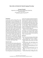
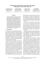
Failed flexible pavements have been recycled with ce-
ment, resulting in a new soil-cement base (Fig. 2.1).
Recycling increases the strength of the base without re-
moving the old existing base and subbase materials and
replacing them with large quantities of expensive new
base materials. In addition, existing grade lines and
drainage can be maintained. If an old bituminous sur-
face can be readily pulverized, it can be considered sat-
isfactory for inclusion in the soil-cement mixture. If, on
the other hand, the bituminous surface retains most of
its original flexibility, it is normally removed rather
than incorporated into the mixture.
The thickness of a soil-cement base depends on var-
ious factors, including: (1)
subgrade
strength, (2) pave-
ment design period, (3) traffic and loading conditions,
including volume and distribution of axle weights, and
(4)
thicknesss
of concrete or bituminous wearing sur-
face. The Portland Cement Association
(PCA),
2,3
the
American Association of State Highway and Transpor-
tation Officials
(AASHTO),
4
and the U.S. Army Corps
of Engineers
(USACE),
5,6
have established methods for
determining design thickness for soil-cement bases.
Most in-service soil-cement bases are 6 in. thick. This
thickness has proved satisfactory for service conditions
associated with secondary roads, residential streets, and
light-traffic air fields. A few 4 and 5 in. thick bases
have given good service under favorable conditions of
light traffic and strong
subgrade
support. Many miles
of 7 and 8 in. thick soil-cement bases are providing
good performance in primary and high-traffic second-
ary pavements. Although soil-cement bases more than
SOIL CEMENT
230.1R-3
Fig.2.1-Old bituminous mat being scarified and pulverized for incorporation in
soil-cement mix
9 in. thick are not common, a few airports and heavy
industrial pavement project
3
have been built with mul-
tilayered thicknesses up to 32 in.
Since 1975, soil-cement base courses incorporating
local soils with
portland
cement and fly ash have been
constructed in 17 states.
7
Specification guidelines and a
contractor’s guide for constructing such base courses
are available from the Electric Power Research Insti-
tute.
8
2.3-Slope protection
Following World War II, there was a rapid expan-
sion of water resource projects in the Great Plains and
South Central regions of the U.S. Rock
riprap
of sat-
isfactory quality for upstream slope protection was not
locally available for many of these projects. High costs
for transporting
riprap
from distant quarries to these
sites threatened the economic feasibility of some proj-
ects. The U.S. Bureau of Reclamation (USBR) initiated
a major research effort to study the suitability of soil
cement as an alternative to conventional
riprap.
Based
on laboratory studies that indicated soil cement made
with sandy soils could produce a durable erosion-resis-
tant facing, the USBR constructed a full-scale test sec-
tion in 1951. A test-section location along the southeast
shore of Bonny Reservoir in eastern Colorado was se-
lected because of severe natural service conditions cre-
ated by waves, ice, and more than 100 freeze-thaw
cycles per year. After 10 years of observing the test sec-
tion, the USBR was convinced of its suitability and
specified soil cement in 1961 as an alternative to
riprap
for slope protection on Merritt Dam, Nebraska, and
later at Cheney Dam, Kansas. Soil cement was bid at
less than 50 percent of the cost of
riprap
and produced
a total savings of more than $1 million for the two
projects.
Performance of these early projects has been good.
Although some repairs have been required for both
Merritt and Cheney Dams, the cost of the repairs was
far less than the cost savings realized by using soil ce-
ment over
riprap.
In addition, the repair costs may
have been less than if
riprap
had been
used.
9
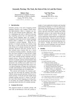
The origi-
nal test section at Bonny Reservoir has required very
little maintenance and still exists today, almost 40 years
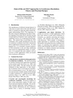
later (Fig. 2.2).
Since 1961, more than 300 major soil-cement slope
protection projects have been built in the U.S. and
Canada. In addition to upstream facing of dams, soil
cement has provided slope protection for channels,
spillways, coastal shorelines, highway and railroad em-
bankments, and embankments for inland reservoirs.
For slopes exposed to moderate to severe wave ac-
tion (effective fetch greater than 1000 ft) or debris-car-
rying, rapid-flowing water, the soil cement is usually
placed in successive horizontal layers 6 to 9 ft wide by
6 to 9 in. thick, adjacent to the slope. This is referred
to as “stairstep slope protection” (Fig. 2.3). For less
severe applications, like those associated with small
reservoirs, ditches, and lagoons, the slope protection
may consist of a 6 to 9 in. thick layer of soil cement
placed parallel to the slope face. This method is often
referred to as “plating” (Fig. 2.4).
The largest soil-cement project worldwide involved
1.2 million yd
3
of soil-cement slope protection for a
230.1 R-4
Fig. 2.2-Soil-cement test section at Bonny Reservoir, Colo., after 34 years
Mini
level
3
Not to scale
Fig. 2.3-Soil-cement slope protection showing layered design
Fig. 2.4-Soil-cement slope plating for cooling water flume at Florida power plant
SOIL CEMENT
230.1R-5
7000-acre
cooling-water reservoir at the South Texas
Nuclear Power Plant near Houston. Completed in
1979, the 39 to 52 ft high embankment was designed to
contain a 15 ft high wave action that would be created
by hurricane winds of up to 155 mph. In addition to the
13 miles of exterior embankment, nearly 7 miles of in-
terior dikes, averaging 27 ft in height, guide the recir-
culating cooling water in the reservoir. To appreciate
the size of this project, if each 6.75 ft wide by 9 in.
thick lift were placed end-to-end rather than in
stair-
step fashion up the embankment, the total distance
covered would be over 1200 miles.
Soil cement has been successfully used as slope pro-
tection for channels and streambanks exposed to lat-
eral flows. In Tucson, Arizona, for example, occa-
sional flooding can cause erosion along the normally
dry river beds. From 1983 to 1988, over 50 soil-cement
slope protection projects were constructed in this area.
A typical section consists of 7 to 9 ft wide horizontal
layers placed in stairstep fashion along 2:l (horizontal
to vertical) embankment slopes. To prevent scouring
and subsequent undermining of the soil cement, the
first layer or two is often placed up to 8 ft below the
existing dry river bottom, and the ends extend approx-
imately 50 ft into the embankment. The exposed slope
facing is generally trimmed smooth during construction
for appearance. To withstand the abrasive force of
stormwater flows of 25,000 to 45,000 ft
3
/sec at veloci-
ties up to 20 ft/sec, the soil cement is designed for a
minimum 7-day compressive strength of 750 psi. In ad-
dition, the cement content is increased by two percent-
age points to allow for field variations.
10
More detailed design information on soil-cement
slope protection can be found in References 11 through
13.
2.4-Liners
Soil cement has served as a low-permeability lining
material for over 30 years. During the
mid-1950s,
a
number of 1 to 2 acre farm reservoirs in southern Cal-
ifornia were lined with 4 to 6 in. thick soil cement. One
of the largest soil-cement-lined projects is Lake
Ca-
huilla, a terminal-regulating reservoir for the Coachella
Valley County Water District irrigation system in
southern California. Completed in 1969, the 135 acre
reservoir bottom has a 6 in. thick soil-cement lining,
and the sand embankments forming the reservoir are
faced with 2 ft of soil cement normal to the slope.
In addition to water-storage reservoirs, soil cement
has been used to line wastewater-treatment lagoons,
sludge-drying beds, ash-settling ponds, and solid waste
landfills. The U.S. Environmental Protection Agency
(EPA) sponsored laboratory tests to evaluate the com-
patibility of a number of lining materials exposed to
various wastes.
14
The tests indicated that after 1 year of
exposure to
leachate
from municipal solid wastes, the
soil cement hardened considerably and cored like
port-
land cement concrete. In addition, it became less
permeable during the exposure period. The soil cement
was also exposed to various hazardous wastes,
includ-
ing toxic pesticide formulations, oil refinery sludges,
toxic pharmaceutical wastes, and rubber and plastic
wastes. Results showed that for these hazardous wastes,
no seepage had occurred through soil cement following
2
1
/2
years of exposure. After 625 days of exposure to
these wastes, the compressive strength of the soil ce-
ment exceeded the compressive strength of similar soil
cement that had not been exposed to the wastes. Soil
cement was not exposed to acid wastes. It was rated
“fair” in containing caustic petroleum sludges, indi-
cating that the specific combination of soil cement and
certain waste materials should be tested and evaluated
for compatibility prior to final design decision.
Mix proportions for liner applications have been
tested in which fly ash replaces soil in the soil-cement
mixture. The fly ash-cement mixture contains 3 to 6
percent
portland
cement and 2 to 3 percent lime.
Permeabilities significantly less than 1 X 10
-7
cm/sec
have been measured for such fly ash-lime-cement mix-
tures, along with unconfined compressive strengths be-
fore and after vacuum saturation, which indicate good
freeze-thaw durability.
Is
A similar evaluation has been
made for liners incorporating fly ash, cement, and
ben-
tonite.16
For hazardous wastes and other impoundments
where maximum seepage protection is required, a com-
posite liner consisting of soil cement
and a
synthetic
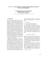
membrane can be used. To demonstrate
the construc-
tion feasibility of the composite liner, a test section was
built in 1983 near Apalachin, N.Y. (Fig. 2.5). The sec-
tion consisted of a 30 and 40 mil high-density polyeth-
ylene (HDPE) membrane placed between two 6-in. lay-
ers of soil cement. After compacting the soil-cement
cover layer, the membrane was inspected for signs of
damage. The membrane proved to be puncture-resis-
tant to the placement and compaction of soil cement
even with
G-in. aggregate scattered beneath the mem-
brane.
17
2.5-Foundation
stabilization
Soil cement has been used as a massive fill to provide
foundation strength and uniform support under large
structures. In Koeberg, South Africa, for example, soil
cement was used to replace an approximately 18 ft thick
layer of medium-dense, liquifiable saturated sand un-
der two
900-MW
nuclear power plants. An extensive
laboratory testing program was conducted to determine
static and dynamic design characteristics, liquefaction
potential, and durability of the soil cement. Results
showed that with only 5 percent cement content by dry
weight, cohesion increased significantly, and it was
possible to obtain a material with enough strength to
prevent liquefaction.
18
Soil cement was used in lieu of a pile or caisson
foundation for a 38-story office building completed in
1980 in Tampa, Fla. A soft limestone layer containing
several cavities immediately below the building made
the installation of piles or caissons difficult and costly.
The alternative to driven foundation supports was to
excavate the soil beneath the building to the top of
230.1R-6
ACI COMMITTEE REPORT
Fig. 2.5-Spreading soil cement on membrane at 3:1 slope, Apalachin, N.Y.
limestone. The cavities within the limestone were filled
with lean concrete to provide a uniform surface prior to
soil-cement placement. The excavated fine sand was
then mixed with cement and returned to the excavation
in compacted layers. The 12 ft thick soil cement mat
saved $400,000 as compared to either a pile or caisson
foundation. In addition to providing the necessary
bearing support for the building, the soil cement dou-
bled as a support for the sheeting required to stabilize
the excavation’s walls. The soil cement was ramped up
against the sheeting and cut back vertically to act as
formwork for the mat pour. As a result, just one brace
was needed for sheeting rather than eight.
19
At the Cochiti Dam site in north-central New Mex-
ico, a 35 ft deep pocket of low-strength clayey shale
under a portion of the outlet works conduit was re-
placed with 57,650 yd
3
of soil cement. The intent of the
massive soil-cement placement was to provide a mate-
rial with physical properties similar to the surrounding
sandstone, thereby minimizing the danger of differen-
tial settlement along the length of the conduit. Uncon-
fined 28-day compressive strengths for the soil cement
were just over 1000 psi, closely approximating the av-
erage unconfined compressive strength of representa-
tive sandstone core samples.
In 1984, soil cement was used instead of mass con-
crete for a 1200 ft wide spillway foundation mat at
Richland
Creek Dam near Ft. Worth, Tex. About 10 ft
of overburden above a solid rock strata was removed
and replaced with 117,500 yd
3
of soil cement. To sat-
isfy the 28-day 1000 psi compressive strength criteria,
10 percent cement content was used. The substitution
of soil cement for mass concrete saved approximately
$7.9 million.
2.6-Miscellaneous applications
Rammed earth is another name for soil cement used
to construct wall systems for residential housing.
Rammed-earth walls, which are generally 2 ft thick, are
constructed by placing the damp soil cement into forms
commonly made of plywood held together by a system
of clamps and whalers. The soil cement is then com-
pacted in 4 to 6 in. thick lifts with a pneumatic tamper.
After the forms are removed, the wall can be stuccoed
or painted to look like any other house. Rammed-earth
homes provide excellent thermal mass insulation prop-
erties; however, the cost of this type of construction
can be greater than comparably equipped frame houses.
A typical rammed-earth soil mix consists of 70 percent
sand and 30 percent noncohesive fine-grained soil. Ce-
ment contents vary from 4 to 15 percent by weight with
the average around 7 percent.
20
Soil cement has been used as stabilized backfill. At
the Dallas Central Wastewater Treatment Plant, soil
cement was used as economical backfill material to
correct an operational problem for 12 large clarifiers.
The clarifiers are square tanks but utilize circular
sweeps. Sludge settles in the corners beyond the reach
of the sweep, resulting in excessive downtime for main-
tenance. To operate more efficiently, sloped fillets of
soil cement were constructed in horizontal layers to
round out the four corners of each tank. A layer of
shotcrete was placed over the soil-cement face to serve
as a protective wearing surface.
Recently, the Texas State Department of Highways
and Public Transportation has specified on several
projects that the fill behind retained earth-wall systems
be cement-stabilized sand. This was done primarily as a
precautionary measure to prevent erosion from behind
the wall and/or under the adjacent roadway.
At some locations, especially where clay is not avail-
able, embankments and dams have been constructed
entirely of soil cement. A monolithic soil-cement em-
bankment serves several purposes. It provides slope
protection, acts as an impervious core, and can be built
SOIL CEMENT
230.1 R-7
on relatively steep slopes due to its inherent shear
strength properties. A monolithic soil-cement embank-
ment was used to form the 1 l00-acre cooling water res-
ervoir for Barney M. Davis Power Plant near Corpus
Christi, Tex. The reservoir consisted of 6.5 miles of
circumferential embankment and 2.1 miles of interior
baffle dikes. The only locally available material for
construction was a uniformly graded beach sand. The
monolithic soil-cement design provided both slope pro-
tection and served as the impervious core. By utilizing
the increased shear strength properties of the com-
pacted cement-stabilized beach sand, the 8 to 22 ft high
embankment was constructed at a relatively steep slope
of 1.5H:1V.
Coal-handling and storage facilities have used soil
cement in a variety of applications. The Sarpy Creek
coal mine, near Hardin, Mont., utilized soil cement in
the construction of a coal storage slot. Slot storage
basically consists of a long V-shaped trough with a re-
claim conveyor at the bottom of the trough. The trough
sidewalls must be at a steep and smooth enough slope
to allow the stored coal to remain in a constant state of
gravity flow. The Sarpy Creek storage trough is 750 ft
long and 20 ft deep. The 15,500
yd
3
of soil cement were
constructed in horizontal layers 22 ft wide at the bot-
tom to 7 ft wide at the top. During construction, the
outer soil-cement edges were trimmed to a finished side
slope of 50 deg. A shotcrete liner was placed over the
soil cement to provide a smooth, highly wear-resistant
surface.
Monolithic soil cement and soil-cement-faced berms
have been used to retain coal in stacker-reclaimer op-
erations. The berm at the Council Bluffs Power Station
in southwestern Iowa is 840 ft long by 36 ft high and
has steep 55 deg side slopes. It was constructed entirely
of soil cement with the interior zone of the berm con-
taining 3 percent cement. To minimize erosion to the
exposed soil cement, the 3.3 ft thick exterior zone was
stabilized with 6 percent cement.
At the Louisa Power Plant near Muscatine, Iowa,
only the exterior face of the coal-retaining berm was
stabilized with soil cement. The 4 ft thick soil cement
and interior uncemented sand fill were constructed to-
gether in 9 in. thick horizontal lifts. A modified as-
phalt paving machine was used to place the soil ce-
ment. A smooth exposed surface was obtained by trail-
ing plates at a
55-deg
angle against the edge during
individual lift construction.
Several coal-pile storage yards have been constructed
of soil cement. Ninety-five acres of coal storage yard
were stabilized with 12 in. of soil cement at the Inde-
pendence Steam Electric Station near Newark, Ark., in
1983. The soil consisted of a processed, crushed lime-
stone aggregate. The 12 in. thick layer was placed in
two 6 in. compacted lifts. By stabilizing the area with
soil cement, the owner was able to eliminate the bed-
ding layer of coal, resulting in an estimated savings of
$3 million. Other advantages cited by the utility include
almost 100 percent coal recovery, a defined perimeter
for its coal pile, reduced fire hazard, and all-weather
access to the area for service and operating equipment.
3-MATERIALS
3.1-Soil
Almost all types of soils can be used for soil cement.
Some exceptions include organic soils, highly plastic
clays, and poorly reacting sandy soils. Tests including
ASTM D 4318 are available to identify these problem
materials.
21,22
Section 5.3 of this report, which focuses
on special design considerations, discusses the subject
of poorly reacting sandy soils in more detail. Granular
soils are preferred. They pulverize and mix more easily
than fine-grained soils and result in more economical
soil cement because they require the least amount of
cement. Typically, soils containing between 5 and 35
percent fines passing a No. 200 sieve produce the most
economical soil cement. However, some soils having
higher fines content (material passing No. 200 sieve)
and low-plasticity have been successfully and economi-
cally stabilized. Soils containing more than 2 percent
organic material are usually considered unacceptable
for stabilization. Types of soil typically used include
silty sand, processed crushed or uncrushed sand and
gravel, and crushed stone.
Aggregate gradation requirements are not as restric-
tive as conventional concrete. Normally the maximum
nominal size aggregate is limited to 2 in.
with
at least
55 percent passing the No. 4 sieve. For unsurfaced soil
cement exposed to moderate erosive forces, such as
slope-protection applications, studies by Nussbaum
23
have shown improved performance where the soil con-
tains at least 20 percent coarse aggregate (granular ma-
terial retained on a No. 4 sieve).
Fine-grained soils generally require more cement for
satisfactory hardening and, in the case of clays, are
usually more difficult to pulverize for proper mixing. In
addition, clay balls (nodules of clay and silt intermixed
with granular soil) do not break down during normal
mixing. Clay balls have a tendency to form when the
plasticity index is greater than 8. For pavements and
other applications not directly exposed to the environ-
ment, the presence of occasional clay balls may not be
detrimental to performance. For slope protection or
other applications where soil cement is exposed to
weathering, the clay balls tend to wash out of the
soil-
cement structure, resulting in a
“swiss
cheese” appear-
ance, which can weaken the soil-cement structure. The
U.S. Bureau of Reclamation requires that clay balls
greater than 1 in. be removed, and imposes a 10 per-
cent limit on clay balls passing the l-in. sieve.
11
The
presence of fines is not always detrimental, however.
Some nonplastic fines in the soil can be beneficial. In
uniformly graded sands or gravels, nonplastic fines in-
cluding fly ash, cement-kiln dust, and aggregate
screenings serve to fill the voids in the soil structure and
help reduce the cement content.
3.2-Cement
For most applications, Type I or Type II portland
cement conforming to ASTM C 150 is normally used.
230.1R-8
ACI COMMITTEE REPORT
Table 3.1
-
Typical cement requirements for various soil
types*’
Typical cement
Typical range
content for Typical cement contents
of cement
moisture-density
for durability tests
AASHTO soil ASTM soil requirement,
*
test (ASTM D
558),
(ASTM D 559 and D
506),
classification
classification percent by weight percent by weight percent by weight
A-l-a
GW, GP, GM,
3-5
5
3-5-7
SW, SP, SM
A-l-b GM, GP, SM, SP
5-8
6
4-6-8
A-2
GM, GC, SM, SC
5-9
7
5-7-9
A-3
SP
7-l 1
9
7-9-l 1
A-4 CL, ML
7-12
10
8-10-12
A-5
ML, MH, CH
8-13
10
8-10-12
A-6 CL, CH
9-15
12
10-12-14
A-7 MH, CH
10-16
13
11-13-15
*Does not include organic or
poorly
reacting, soils. Also, additional cement may be required for severe exposure
conditions such as slope-protect&.
Cement requirements vary depending on desired prop-
erties and type of soils. Cement contents may range
from as low as 4 to a high of 16 percent by dry weight
of soil. Generally, as the clayey portion of the soil in-
creases, the quantity of cement required increases. The
reader is cautioned that the cement ranges shown in
Table 3.1 are not mix-design recommendations. The
table provides initial estimates for the mix-proportion-
ing procedures discussed in Chapter 5.
3.3-Admixtures
Pozzolans such as fly ash have been used where the
advantages outweigh the disadvantages of storing and
handling an extra material. Where pozzolans are used
as a cementitious material, they should comply with
ASTM C 618. The quantity of cement and pozzolan
required should be determined through a laboratory
testing program using the specific cement type,
pozzo-
lan, and soil to be used in the application.
For highly plastic clay soils, hydrated lime or quick-
lime may sometimes be used as a pretreatment to re-
duce plasticity and make the soil more friable and sus-
ceptible to pulverization prior to mixing with cement.
Chemical admixtures are rarely used in soil cement. Al-
though research has been conducted in this area, it has
been primarily limited to laboratory studies with few
field investigation.
24-29
3.4-Water
Water is necessary in soil cement to help obtain max-
imum compaction and for hydration of the portland
cement. Moisture contents of soil cement are usually in
the range of 10 to 13 percent by weight of oven-dry soil
cement.
Potable water or other relatively clean water, free
from harmful amounts of alkalies, acids, or organic
matter, may be used. Seawater has been used satisfac-
torily. The presence of chlorides in seawater may in-
crease early strengths.
4-PROPERTIES
4.1-General
The properties of soil cement are influenced by sev-
eral factors, including (a) type and proportion of soil,
cementitious materials, and water content, (b) compac-
tion, (c) uniformity of mixing, (d) curing conditions,
and (e) age of the compacted mixture. Because of these
factors, a wide range of values for specific properties
may exist. This chapter provides information on sev-
eral properties and how these and other factors affect
various properties.
4.2-Density
Density of soil cement is usually measured in terms
of dry density, although moist density may be used for
field density control. The moisture-density test (ASTM
D 558) is used to determine proper moisture content
and density (referred to as optimum moisture content
and maximum dry density) to which the soil-cement
mixture is compacted. A typical moisture-density curve
is shown in Fig. 4.1. Adding cement to a soil generally
causes some change in both the optimum moisture con-
tent and maximum dry density for a given compactive
effort. However, the direction of this change is not
usually predictable. The flocculating action of the ce-
ment tends to produce an increase in optimum mois-
ture content and a decrease in maximum density, while
the high specific gravity of the cement relative to the
soil tends to produce a higher density. In general,
Shen
30
showed that for a given cement content, the
higher the density, the higher the compressive strength
of cohesionless soil-cement mixtures.
Prolonged delays between the mixing of soil cement
and compaction have an influence on both density and
strength. Studies by
West
31
showed that a delay of more
than 2 hr between mixing and compaction results in a
significant decrease in both density and compressive
strength. Felt
32
had similar findings but also showed
that the effect of time delay was minimized, provided
the mixture was intermittently mixed several times an
hour, and the moisture content at the time ‘of compac-
tion was at or slightly above optimum.
SOIL CEMENT
230.1R-9
125
.;
120
r
z
yMaximum
density
&
Optimum moisture
;
115
L
21
C
t
g
z
110
I
I
0
I
1
2
I
6
I
105
I
I
I
I
IOO-
I
5 10
15
20 25
Moisture content, percent
Fig. 4. 1- Typical moisture-density curve
400
-
Table 4.1
-
Ranges of unconfined compressive
strengths of
soil-cement33
Silty soils:
AASHTO groups
A-4
and A-5
Unified groups ML and CL
Clayey soils:
AASHTO groups A-6 and A-7
Unified groups MH and CH
I
I
200-400
250-600
*Specimens moist-cured 7 or 28 days, then soaked in water prior to strength
testing.
4.3-Compressive strength
Unconfined compressive strengthf,’ is the most
widely referenced property of soil cement and is usu-
ally measured according to ASTM D 1633. It indicates
the degree of reaction of the soil-cement-water mixture
and the rate of hardening. Compressive strength serves
as a criterion for determining minimum cement re-
quirements for proportioning soil cement. Because
strength is directly related to density, this property is
affected in the same manner as density by degree of
compaction and water content.
Typical ranges of
7-
and
28-day
unconfined com-
pressive strengths for soaked, soil-cement specimens are
given in Table 4.1. Soaking specimens prior to testing
is recommended since most soil-cement structures may
become permanently or intermittently saturated during
their service life and exhibit lower strength under satu-
rated conditions. These data are grouped under broad
textural soil groups and include the range of soil types
normally used in soil-cement construction. The range of
values given are representative for a majority of soils
2800
0
COARSE
-
GRAINED
SOILS
.
FINE
-
GRAINED SOILS
f,-
UNCONFINED COMPRESSIVE
2400 _
STRENGTH
C
-
CEMENT CONTENT
0
I I
I
0
5 10
15
20
25
CEMENT CONTENT
(%
BY WEIGHT)
Fig. 4.2-Relationship between cement content and
unconfined compressive strength for soil-cement mix-
tures
normally used in the United States in soil-cement con-
struction. Fig. 4.2 shows that a linear relationship can
be used to approximate the relationship between com-
pressive strength and cement content, for cement con-
tents up to 15 percent and a curing period of 28 days.
Curing time influences strength gain differently de-
pending on the type of soil. As shown in Fig. 4.3, the
strength increase is greater for granular soil cement
than for fine-grained soil cement.
4.4-Flexural (tensile) strength (modulus of
rupture)
Flexural-beam tests (ASTM D
1635),
direct-tension
tests, and split-tension tests have all been used to eval-
uate
flexural
strength.
Flexural
strength is about
one-
fifth to one-third of the unconfined compressive
strength. Data for some soils are shown in Fig. 4.4. The
ratio of flexural to compressive strength is higher in
low-strength mixtures (up to
l/3
fi
) than in high-
strength mixtures (down to less than
l/5
ff
).
A good
approximation for the
flexural
strength
R
is
34
where
R = 0.51
(f,‘)“.“”
R
=
flexural
strength, psi
f,’ = unconfined compressive strength, psi
230.1 R-l 0
ACI COMMITTEE REPORT
500
o GRANULAR SOILS
0
c
. FINE
-
GRAINED
SOILS
COARSE
-
GRAINED
SOILS WITH 10% CEMENT
FINE
-
GRAINED SOILS WITH 10% CEMENT
01
I
I I
I
0 500
1000 1500
2ooo
2500
UNCONFINED COMPRESSIVE STRENGTH (psi)
10
100
1000
CURING TIME
(days)
Fig. 4.4-Relationship between unconfined compres-
sive strength and
flexural
strength of soil-cement
mixtures34
Fig. 4.3-Effect of curing time on unconfined concrete
compressive strength of some soil-cement
mixture34
Table 4.2
-
Permeability of cement-treated
soils
17
Gradation analysis,
K
coefficient of
percent passing
Cement permeability ft
Cement*
content
per
yr,
005 0005 required,
percent by weight
10
-6
cm/sec
(4.7t4mm)
(2.o#‘im)
(42!4zm)
(7;2E)
mm
mm by weight
ASTM soil
classification
Dry
density,
lb/ft
3
Standard Ottawa
sand
108.2
112.8
117.6
Moisture
content,
percent
10.8
;:‘:
0
48,800
(100 percent passing
#20
(850
pm):
0 percent passing
5.3 6900
#30
(600
urn)
-
Graded Ottawa
sand
103.2 13.7
104.7 13.6
107.4
12.3
10.5 76
0 16,300
100
100
1;::
470
21
Fine sand (SP)
101 .o
12.2
100.9
13.2
103.6
12.3
105.3
12.0
0
750
100 100
3.2
560
:::
190
21
Silty sand (SM)
100.8
14.9
99.9
14.7
104.0
15.1
0
5000
100
100
i:f
1400
60
Fine sand (SP)
100.1 16.0
105.8 14.8
109.3 13.5
0
I
360
I
99 99
6
20
Fine sand (SP)
101.0 13.8
106.7 13.3
108.2 13.4
108.8
13.4
Fine sand (SP)
112.5
115.8
11.0
10.4
12.2
1
0
140
100 100
:*:
33
9:6
E2
0 36
-
97
5.5
5
Fine sand (SP)
111.7
12.0
0
I
23 100
99
115.2 11.7
5.5
8
Silty sand (SM)
121.9
9.6
125.5
8.0
Silty sand (SM)
117.9 10.8
123.0
8.1
Silty sand (SM)
112.5
11.5
115.0 12.3
Silty sand (SM)
118.7
119.2
11.0
10.5
Silty sand (SM)
125.0
lo,1
0
16
98 94
8.6
0.1
0
10
99
97
8.9
2
0
:
-
98
5.5
g.1
i.1
100
99
0
16
100 75
3.3
7.3
E7
.
.,
28
2
-
91
7 1
-
11.5
96
13 12 2
8.0
96
6 61
-
94
2
11.0
*Cement requirement based on ASTM Standard Freeze-Thaw and Wet-Dry Tests for soil-cement mixtures and PCA paving criteria.
SOIL CEMENT
230.1 R-11
Values of tensile strength deduced from the results of
flexure, direct-tension, and split-tension tests may dif-
fer, due to the effects of stress concentrations and dif-
ferences between moduli in tension and compression.
Research by
Radd
35
has shown that the split-tension test
yields values that do not deviate by more than 13 per-
cent from the direct tensile strength.
4.5-Permeability
Permeability of most soils is reduced by the addition
of cement. Table 4.2 summarizes results from labora-
tory permeability tests conducted on a variety of soil
types. A large-scale seepage test was performed by the
U.S. Bureau of Reclamation on a section of layered
stairstep soil cement facing at Lubbock Regulating
Reservoir in Texas.
36
Results indicated a decrease in
permeability with time, possibly due to shrinkage
cracks in the soil-cement filling with sediment and the
tendency for the cracks to self-heal. Seepage was as
much as 10 times greater in the cold winter months than
the hot summer months. The reduced summer seepage
was probably caused by thermal expansion which nar-
rowed the crack widths and by the presence of algae
growth in the cracks.
In multiple-lift construction, higher permeability can
generally be expected along the horizontal surfaces of
the lifts than perpendicluar to the lifts. Research by
Nussbaum
23
has shown permeabilities for flow parallel
to the compaction plane were 2 to 20 times larger than
values for flow normal to the compaction plane.
4.6-Shrinkage
Cement-treated soils undergo shrinkage during
drying. The shrinkage and subsequent cracking depend
on cement content, soil type, water content, degree of
compaction, and curing conditions. Fig. 4.5 shows the
results of field data on shrinkage cracking from five
test locations in Australia.
37
Soil cement made from
each soil type produces a different crack pattern. Soil
cement made with clays develops higher total shrink-
age, but crack widths are smaller and individual cracks
more closely spaced (e.g., hairline cracks, spaced 2 to
10 ft apart). Soil cement made with granular soils pro-
duces less shrinkage, but larger cracks spaced at greater
intervals (usually 10 to 20 ft or more apart).
33
Methods
suggested for reducing or minimizing shrinkage cracks
include keeping the soil-cement surface moist beyond
the normal curing periods and placing the soil cement
at slightly below optimum moisture content.
4.7-Layer coefficients and structural numbers
Several different methods are currently being used
for pavement design. In the AASHTO method for
flexible pavement design, layer coefficient a, values are
assigned to each layer of material in the pavement
structure to convert actual layer thicknesses into a
structural number SN. This layer coefficient expresses
the empirical relationship between SN and thickness
D,
and is a measure of the relative ability of the material
to function as a structural component of the pavement.
SIZE OF CRACK OPENING
(in.)
Fig. 4.5-Frequency distribution of various sizes of
shrinkage cracks in soil
cement
37
Table 4.3
-
Examples of AASHTO layer
coefficients for soil cement used by various
state
DOTs
State
Alabama
Arizona
Delaware
0.20
Florida
Georgia
Louisiana
Montana
New Mexico
Pennsylvania
Wisconsin
Layer
coefficient
0
0.23
0.20
0.15
~____
0.28
0.23
0.15
300 psi (mixed-in-place)
0.20
500
psi (plant mixed)
0.20
350 psi
0.15
0.18
0.23
200 psi min
400 psi min
Shell and sand with 650 psi
min
0.20
400 psi min
0.23
650 psi min
0.17
400-650
psi
0.12
Less than 400 psi
0.20
650 psi min (mixed-in-place)
0.30
650 psi min (plant mixed)
0.23
650 psi min
0.20
400-650
psi
0.15
Less than 400 psi
Compressive
strength requirement
650 psi min
400-650 psi
Less than 400 psi
For cement-treated base
with minimum 800 psi (plant
mixed)
For cement-treated
subgrade
with
800
psi min (mixed-in-
place)
The following general equation for structural number
reflects the relative impact of the layer coefficient and
thickness
4
SN
-
a,D, + a
2
D
2
+ a3D3
where a
1
, a
2
, and a
3
= layer coefficients of surface,
base, and subbase, respectively; and D
1
,
D
2
,
and D
3
=
corresponding layer thicknesses.
230.1 R-l 2
ACI COMMITTEE REPORT
Table 5.1
-
PCA criteria for soil-cement as indicated by wet-dry and
freeze-thaw durability
tests
1
AASHTO
Unified soil
Maximum allowable weight
soil group
group
loss, percent
A-l-a GW, GP, GM, SW, SP, SM
14
A-l-b
GM, GP, SM, SP
14
A-2
GM, GC, SM, SC
14*
A-3 SP
14
A-4
CL, ML
10
A-5
ML, MH, CH
10
A-6
CL, CH
7
A-7
OH, MH, CH 7
*10
percent is
maximum allowable weight loss for A-2-6 and A-2-7 soils.
Additional criteria
1. Maximum volume changes during durability test should be less than 2 percent of the initial volume.
2. Maximum water content during the test should be less than the quantity required to saturate the sample at the
time of molding.
3. Compressive strength should increase with age of specimen.
4. The cement content determined as adequate for pavement, using the PCA criteria above, will be adequate for
soil-cement slope protection that is 5 ft or more below the minimum water elevation. For soil cement that is
higher than that elevation, the cement
content should be increased two percentage points.
The layer coefficients are actually the average of a set
of multiple regression coefficients, which indicate the
effect of the wearing course, the base course, and the
subbase on the pavement’s performance. Typical
soil-
cement layer coefficient a, values used by state depart-
ments of transportation are given in Table 4.3.
5-MIX PROPORTIONING
5.1-General
The principal structural requirements of a hardened
soil-cement mixture are based on adequate strength and
durability. For water resource applications such as lin-
ers, permeability may be the principal requirement. Ta-
ble 3.1 indicates typical cement contents for pavement
applications. Detailed test procedures for evaluating
mix proportions are given in the Portland Cement As-
sociation Soil-Cement Laboratory Handbook
1
and by
the following ASTM test standards:
ASTM
D
558
ASTM
D559
ASTMD
560
ASTM
D
1557
ASTM
D
1632
ASTM
D
1633
ASTM
D
2901
Test for Moisture-Density Relations of
Soil-Cement Mixtures
Wetting-and-Drying Tests of Com-
pacted Soil-Cement Mixtures
Freezing-and-Thawing Tests of Com-
pacted Soil-Cement Mixtures
Moisture-Density Relations of Soils
and Soil Aggregate Mixtures Using
10-
lb Rammer and 18-in. Drop
Making and Curing Soil-Cement
Compression and Flexure Test Speci-
mens in the Laboratory
Test for Compression Strength of
Molded Soil-Cement Cylinders
Test for Cement Content of Freshly
Mixed Soil-Cement
5.2-Proportioning
Various criteria are used by different organizations to
determine acceptable mix proportions. The Portland
Table 5.2
-
USACE
durability requirement
38
Maximum allowable weight loss after
Type of soil
12 wet-dry or freeze-thaw cycles,
stabilized*
percent of initial specimen weight
Granular, PI<
10
11
Granular, PI>
10
Silt
:
Clays
6
*Refer to MIL-STD-619B and MIL-STD-621A, U.S. Army corps of Engi-
neers.
Table 5.3
-
USACE
minimum unconfined
compressive strength
criteria
38
Minimum unconfined compressive
Flexible pavement Rigid pavement
,,:““m
Subbase course, select material or
Cement Association (PCA) criteria are summarized in
Table 5.1. Cement contents sufficient to prevent weight
losses greater than the values indicated after 12 cycles
of wetting-drying-brushing or freezing-thawing-brush-
ing are considered adequate to produce a durable soil
cement.
The U.S. Army Corps of Engineers
(USACE)
fol-
lows its technical manual, “Soil Stabilization for Pave-
ments,”
TM
5-822-4.
38
The durability and strength re-
quirements for portland cement stabilization are given
in Tables 5.2 and 5.3, respectively.
USACE
requires
that both criteria be met before a stabilized layer can be
used to reduce the required surface thickness in the de-
sign of a pavement system. USACE frequently in-
creases the cement content by 1 or 2 percent to account
for field variations. For bank protection,
USACE
has
an unnumbered draft Engineer Technical letter for in-
terim guidance.
39
The U.S. Bureau of Reclamation (USBR) design cri-
teria for soil-cement slope protection on dams allow
maximum losses during freeze-thaw and wet-dry dura-
SOIL CEMENT
230.1 R-13
bility tests of 8 and 6 percent, respectively. These crite-
ria were developed specifically for soil cement slope
protection using primarily silty sands. In addition,
USBR requires a minimum compressive strength of 600
psi at 7 days and 875 psi at 28 days. To allow for vari-
ations in the field, it is
USBR’s
practice to add two
percentage points to the minimum cement content that
meets all of the preceding design criteria.
11
Pima County, Ariz., uses a considerable amount of
soil cement for streambank slope protection. The
county requires the soil cement to have a minimum
7-day compressive strength of 750 psi. The cement con-
tent is increased two percentage points for additional
erosion resistance and to compensate for field varia-
tion. This results in a 7-day compressive strength of
about 1000 psi. To facilitate quality-control testing
during construction, the county has established an ac-
ceptance criterion based on a l-day compressive
strength test. For the local soils typically used, the
l-day strength is generally between 50 to 60 percent of
the 7-day value.
The PCA Soil-Cement Laboratory Handbook
1
de-
scribes a shortcut test procedure that can be used to de-
termine the cement content for sandy soils. The proce-
dure uses charts developed from previous tests on sim-
ilar soils. The only tests required are a sieve analysis, a
moisture-density test, and a compressive strength test.
Relatively small samples are needed. All tests can be
completed in 1 day, except the 7-day compressive
strength test.
5.3-Special considerations
5.3.1 Strength versus durability-In many soil-ce-
ment applications, both strength and durability re-
quirements must be met to achieve satisfactory service
life. ASTM D 559 and D 560 are standard test methods
that are conducted to determine, for a particular soil,
the amount of cement needed to hold the mass together
permanently and to maintain stability under the
shrinkage and expansive forces that occur in the field.
It is common practice, however, to use compressive
strength to determine the minimum cement content.
Fig. 5.1 illustrates the general relationship between
compressive strength and durability for soil cement. It
is apparent from these curves that a compressive
strength of 800 psi would be adequate for all soils, but
this strength would be higher than needed for most soils
and would result in a conservative and more costly de-
sign. The determination of a suitable design compres-
sive strength is simplified when materials within a nar-
row range of gradations and/or soil types are used. As
a result, some agencies have determined and used suc-
cessfully, for a particular type of material, a compres-
sive strength requirement generally based on results of
the wet-dry and freeze-thaw tests.
5.3.2 Compressive strength specimen size-Comp-
ressive strength tests are frequently conducted on test
specimens obtained from molds commonly available in
soil laboratories and used for other soil-cement tests.
These test specimens are 4.0 in. in diameter and 4.584
I
I
I I
20
40
60
80
%
OF SAMPLES PASSING
ASTM FREEZE-THAW
&
WET-DRY TESTS
1'
Fig.
5.1-Relationship
between compressive strength
and durability of soil cement based on Portland Ce-
ment Association durability criteria
1
in. in height with a height-to-diameter (h/d) ratio of
1.15. This differs from conventional concrete molds,
which use h/d of 2.00. The h/d of 2.00 provides a more
accurate measure of compressive strength from a tech-
nical viewpoint, since it reduces complex stress condi-
tions that may occur during crushing of lower h/d
specimens. In soil-cement testing, however, the lower
h/d (1.15) specimens are frequently used. Most of the
compressive strength values given in this report are
based on h/d = 1.15. Using the correction factor for
concrete given in ASTM C 42, an approximate correc-
tion can be made for specimens with h/d of 2.00 by
multiplying the compressive strength value by a factor
of 1.10.
5.3.3 Poorly reacting sandy soils-Occasionally, cer-
tain types of sandy soils are encountered that cannot be
treated successfully with normal amounts of portland
cement. Early research
21
showed that organic material
of an acidic nature usually had an adverse effect on soil
cement. The study showed that organic content and
pH
do not in themselves constitute an indication of a
poorly reacting sand. However, a sandy soil with an
organic content greater than 2 percent or having a
pH
lower than 5.3, in all probability, will not react nor-
mally with cement. These soils require special studies
prior to use in soil cement.
5.3.4 Sulfate resistance-As with conventional con-
crete, sulfates will generally attack soil cement. Studies
by Cordon and Sherwood
40,41
have indicated that the
resistance to sulfate attack differs for cement-treated
coarse-grained and fine-grained soils and is a function
of the clay and sulfate concentrations. The studies
showed that sulfate-clay reactions are more detrimental
than sulfate-cement reactions, resulting in deterioration
of fine-grained soil cement more rapidly than
coarse-
230.1R-14
ACI COMMITTEE REPORT
grained
soil cement. Also, increasing the cement con-
tent of soil-cement mixtures may be more beneficial
than changing to a sulfate-resistant type of cement.
6-CONSTRUCTION
6.1-General
In the construction of soil cement, the objective is to
obtain a thoroughly mixed, adequately compacted, and
cured material. Several references are available
8,13,42-44
that discuss soil-cement construction methods for var-
ious applications. Specifications on soil-cement con-
struction are also readily available.
45-47
Soil cement should not be mixed or placed when the
soil or
subgrade
is frozen or when the air temperature
is below 45 F. However, a common practice is to pro-
ceed with construction when the air temperature is at
least 40 F and rising. When the air temperature is ex-
pected to reach the freezing point, the soil cement
should be protected from freezing for at least 7 days.
Soil-cement construction typically requires the addition
of water equivalent to 1 to 1
l/
in. of rain; therefore, a
Fig. 6. 1 Transverse single-shaft mixer processing
cement in place; multiple passes are required
soil
light rainfall should not delay construction. However,
a heavy rainfall that occurs after most of the water has
been added can be detrimental. If rain falls during ce-
ment-spreading operations, spreading should be
stopped and the cement already spread should be
quickly mixed into the soil mass. Compaction should
begin immediately and continue until the soil cement is
completely compacted. After the mixture has been
compacted, rain usually will not harm it.
6.2-Materials handling and mixing
Soil cement is either mixed in place or mixed in a
central mixing plant. The typical types of mixing
equipment are:
1. In-place traveling mixers
a. Transverse single-shaft mixer
b. Windrow-type
pugmill
2. Central mixing plant
a. Continuous-flow-type
pugmill
b. Batch-type
pugmill
c. Rotary-drum mixer
6.2.1 Mixed in place
Mixing operations with
subgrade
materials are performed with transverse sin-
gle-shaft-type mixers (Fig. 6.1 and 6.2). Mixing with
borrow materials may be performed with single-shaft or
windrow-type pugmill mixers (Fig. 6.3). Almost all
types of soil, from granular to fine-grained, can be ad-
equately pulverized and mixed with transverse
single-
shaft mixers. Windrow-type
pugmills
are generally lim-
ited to nonplastic to slightly plastic granular soils.
6.2.1.1 Soil preparation-During grading opera-
tions, all soft or wet subgrade areas are located and
corrected. All deleterious material such as stumps,
roots, organic soils, and aggregates larger than 3 in.
should be removed. For single-shaft mixers, the soil is
shaped to the approximate final lines and grades prior
to mixing. Proper moisture content aids in pulveriza-
tion. For granular soils, mixing at less than optimum
moisture content minimizes the chances for cement
balls to form. For fine-grained soils, moisture content
near optimum may be necessary for effective pulveri-
zation.
Fig. 6.2-Mixing chamber of a transverse single-shaft
mixer
Fig. 6.3- Windrow-type traveling pugmill mixing soil
cement from
windrows
of soil material
SOILNCEMENT
230.1 R-15
6.2.1.2 Cement application-Cement is generally
distributed in bulk using a mechanical spreader (two
examples of which are shown in Fig. 6.4 and 6.5) or,
for small projects, by hand-placing individual cement
bags. The primary objective of the cement-spreading
operation is to achieve uniform distribution of the ce-
ment in the proper proportions.
To obtain a uniform cement spread, the mechanical
spreader must be operated at uniform speed with a rel-
atively constant level of cement in the hopper. The
spreader must have adequate traction to produce a uni-
form cement spread. Traction can be aided by wetting
and rolling the soil before spreading the cement. When
operating in loose sands or gravel, slippage can be
overcome by using cleats on the spreader wheels. The
mechanical cement-spreader can also be attached di-
rectly behind a bulk-cement truck. Cement is moved
pneumatically from the truck through an air-separator
cyclone that dissipates the air pressure; it then falls into
the hopper of the spreader. Forward speed must be
slow and even. Sometimes a motor grader or loader
pulls the truck to maintain this slow, even, forward
speed. Although pipe cement-spreaders attached to ce-
ment-transport trucks have been used in some areas
with mixed results, mechanical spreaders are generally
preferred. The amount of cement required is specified
as a percentage by weight of oven-dry soil, or in lb of
cement per ft
3
of compacted soil cement. Table 6.1 can
be used to determine quantities of cement per yd
2
of
soil-cement placement.
Fig.
6.4-Mechanical
cement spreader attached to
dump truck
6.2.1.3 Pulverization and mixing-Single-shaft
mixers are typically utilized to pulverize and mix ce-
ment with
subgrade
soils. Agricultural-type equipment
is not recommended due to relatively poor mixing uni-
formity. Pulverization and mixing difficulties increase
with higher fines content and plasticity of the soils
being treated. In-place mixing efficiency, as measured
by the strength of the treated soil, may be less than that
obtained in the laboratory. This reduced efficiency is
sometimes compensated for by increasing the cement
content by 1 or 2 percentage points from that deter-
mined in the laboratory testing program.
Fig. 6.5-Mechanical cement spreader attached to bulk
cement transport truck
Table 6.1
-
Cement spread
requirement
51
Windrow-type traveling mixing machines will pulver-
ize friable soils. Nonfriable soils, however, may need
preliminary pulverizing for proper mixing. This is usu-
ally done before the soil is placed in
windrows
for pro-
cessing. The prepared soil is bladed into
windrows
and
a “proportioning”device is pulled along to provide a
uniform cross section. When borrow materials are
used, a
windrow
spreader can be used to proportion the
material. Nonuniform
windrows
cause variations in ce-
ment content, moisture content, and thickness. The
number and size of windrows needed depend on the
width and depth of treatment and on the capacity of
the mixing machine.
Cement content,
lb/ft
3
of
compacted
soil cement
Cement spread,
lb/yd
2
/in. of
thickness of
compacted
soil cement
Cement is spread on top of a partially flattened or
slightly trenched prepared
windrow.
A mixing machine
then picks up the soil and cement and dry-mixes them
with the first few paddles in the mixing drum. At that
point, water is added through spray nozzles and the
re-
4.5
5.0
i-i
6.5
7.0
7.5
K
E
10.0
10.5
11.0
11.5
12.0
12.5
13.0
13.5
14.0
14.5
15.0
15.5
16.0
3.38
3.75
4.13
4.50
4.88
5.25
5.63
6.0
6.38
6.75
7.13
7.50
7.88
8.25
8.63
E8
9.75
10.13
10.50
10.88
11.25
1
1.63
12.0
230.1 R-16
ACI COMMITTEE REPORT
Fig. 6.6- Vibrating screen removing oversized material
from soil portion of mixture
maining paddles complete the mixing. A strikeoff at-
tached to the mixing machine spreads the mixed soil
cement.
6.2.2 Central plant mixing-Central mixing plants
are normally used for projects involving borrow mate-
rials. Granular borrow materials are generally used be-
cause of their low cement requirements and ease in
handling and mixing. Clayey soils or materials contain-
ing clay lenses should be avoided because they are
dif-
ficul to pulverize. There are two basic types of central
plant mixers-pugmill mixers, either continuous-flow
or batch, and rotary-drum mixers. Although batch
pugmills
and rotary-drum mixers have been used satis-
factorily, the most common central plant mixing
method is the continuous-flow
pugmill
mixer. Produc-
tion rates with this type of mixer vary between 200 and
800
t/hr.
6.2.2.1 Borrow material-Soil borrow sources are
usually located near the construction site. Natural
de-
posits are generally variable to an extent and do not
contain consistent, uniform materials throughout.
The U.S. Bureau of Reclamation recommends the
following procedure for handling borrow materia1.
48
If
the material in the borrow area varies with depth,
full-
face cuts should be made with the excavation ma-
chinery. This selective excavation insures that some
material from each layer is obtained in each cut. If the
material varies laterally across the borrow area, or dif-
fers from one spot to another, loads from different lo-
cations in the borrow area should be mixed. After the
material has been excavated, soil can be further blended
at the stockpile. Alternating the loads from different
parts of the borrow area helps to blend soil gradations
in the stockpile. Mixing for uniformity of gradation
and moisture can also be done as the material is pushed
into the stockpile. For example, if excavated material is
dumped at the base of the stockpile, it can be pushed
up the stockpile with a bulldozer. A front-end loader
can then be used to load the soil feed. This tends to mix
a vertical cut of the stockpile, which causes further
mixing of any layers that might exist in the pile.
As the borrow material is excavated it should be
checked for unsuitable material such as clay lenses,
cobbles, or cemented conglomerates. Such materials do
not adequately break down in a pugmill mixer. Re-
moval of some oversize clay balls and other
large
par-
ticles can be done by screening through 1 to 1
%-in.
mesh (Fig. 6.6). In some cases, selective excavation may
be necessary to avoid excessive clay lenses.
6.2.2.2 Mixing-The objective is to produce a
thorough and intimate mixture of the soil, cement, and
water in the correct proportions. A diagram of a con-
tinuous-flow
pugmill
plant is shown in Fig. 6.7. A typ-
ical plant consists of a soil bin or stockpile, a cement
silo with surge hopper, a conveyor belt to deliver the
soil and cement to the mixing chambers, a mixing
chamber, a water-storage tank for adding water during
mixing, and a holding or gob hopper to temporarily
store the mixed soil cement prior to loading (Fig. 6.8).
A
pugmill
mixing chamber consists of two parallel
shafts equipped with paddles along each shaft (Fig.
Cement storoqe silo-
Water meter
Pug mill mixer
continuous flow- twin screw
Vane feeder (feeds cement
-Storage
hopper
Retaining
wall
-
Fig. 6.7-Diagram of continuous-flow central plant for mixing soil cement
SOIL CEMENT
230.1 R-l 7
6.9). The twin-shafts rotate in opposite directions, and
the soil cement is moved through the mixer by the pitch
of the paddles.
Material feed, belt speed,
pugmill
tilt, and paddle
pitch are adjusted to optimize the amount of mixing in
the pugmill. Thorough blending in the mixer is very
important, and the length of mixing time is used to
control this factor. Some specifications dictate the
minimum blending time. Usually 30
sec
is specified, al-
though satisfactory blending has been achieved in
shorter periods, depending on the efficiency of the
mixer.
6.2.2.3 Transporting-To reduce evaporation
losses during hot, windy conditions and to protect
against sudden showers, rear and bottom dump trucks
are often equipped with protective covers. No more
than 60 min should elapse between the start of
moist-
mixing and the start of compaction. Haul time is usu-
ally limited to 30 min.
For multiple-layer stairstep construction, as used for
slope protection, earthen ramps are constructed at in-
tervals along the slope to enable trucks to reach the
layer to be placed. These are constructed at a 45 deg
horizontal angle to the slope, normally 2 ft thick and
spaced about 300 to 400 ft apart.
At large-volume projects, such as the South Texas
Nuclear Power Plant, a conveyor system can be used to
deliver the soil cement to the spreader. This removes
the necessity for ramp construction and truck maneu-
vering, and provides a cleaner end-product. Narrower
layers can also be placed using the conveyor system,
since the width needed to facilitate the haul trucks is
eliminated. The soil cement can be delivered either
from above or below directly to a spreader box.
6.2.2.4 Placing and spreading-The mixed soil ce-
ment should be placed on a firm subgrade, without
segregation, and in a quantity that will produce a com-
pacted layer of uniform thickness and density con-
forming to the design grade and cross section. The
subgrade
and all adjacent surfaces should be moistened
prior to placing soil cement.
There is a wide variety of spreading devices and
methods. Using a motor grader or spreader box at-
tached to a dozer are the most commonly used means.
Spreading may also be done with asphalt-type pavers.
Some pavers are equipped with one or more tamping
bars, which provide initial compaction. Soil cement is
usually placed in a layer 25 to 50 percent thicker than
the final compacted thickness. For example, a 8 to 9 in.
loosely placed layer will produce a compacted thickness
of about 6 in. This relationship varies slightly with the
type of soil, method of placement and degree of com-
paction. The actual thickness of the loosely spread layer
is determined from contractor experience or
trial-and-
error methods. Compacting, finishing, and curing fol-
low the same procedures as for mixed-in-place con-
struction.
6.2.2.5 Bonding successive layers Bonding suc-
cessive layers of soil cement is an important require-
ment for applications such as slope protection. It is
es-
Fig. 6.8- Typical continuous-flow central mixing plant
Fig. 6.9-Mixing paddles of a twin-shaft,
continuous
flow cen
tral
mixing plant
sential that each completed surface remain clean and
moist, but not wet, until it is covered with the next
layer. Mud and debris tracked onto a surface will sig-
nificantly reduce bonding. Other methods which have
been effective in improving bond between layers in-
clude the following:
49,50
1. Minimizing time between placement of successive
layers.
2. Use of either dry cement or cement slurry. The dry
cement should be applied at about 1
lb/yd
2
to a mois-
tened surface immediately prior to placement. The ce-
ment slurry mix should have a water-cement ratio of
about 0.70 to 0.80.
3. After the soil cement has set, brushing the surface
with a power broom to provide a roughened surface
texture.
4. Use of chemical retarding agents.
6.3-Compaction
’
Compaction begins as soon as possible and is gener-
ally completed within 2 hr of initial mixing. The detri-
mental effects of delayed compaction on density and
strength have already been described in Section 4.2. No
section is left unworked for longer than 30 min during
230.1 R-18
ACI COMMITTEE REPORT
Fig. 6.10-Compacting outer edge with rounded steel
flange welded to steel-wheel roller
compaction operations. The principles governing com-
paction of soil cement are the same as those for com-
pacting the same soil without cement treatment. For
maximum density, the soil-cement mixture should be
compacted at or near optimum moisture content as de-
termined by ASTM D 558 or D-1557. Most specifica-
tions require soil cement to be uniformly compacted to
a minimum of between 95 and 98 percent of maximum
density. Moisture loss by evaporation during compac-
tion, indicated by a graying of the surface, should be
replaced with light applications of water.
Various types of rollers have been used for soil ce-
ment. Tamping or sheepsfoot rollers are used for initial
compaction of fine-grained soils. The sheepsfoot roller
is often followed by a multiple-wheel, rubber-tired
roller for finishing. For granular soils, vibratory
steel-
wheeled or heavy rubber-tired rollers are generally used.
To obtain adequate compaction, it is sometimes neces-
sary to operate the rollers with ballast to produce
greater contact pressure. The general rule is to use the
greatest contact pressure that will not exceed the bear-
ing capacity of the soil-cement mixture. Compacted
layer thicknesses generally range from 6 to 9 in. Greater
thicknesses, particularly for granular soils, can be com-
pacted with heavy equipment designed for thicker lifts.
Regardless of the lift thickness and compaction equip-
ment used, the fundamental requirement is that the
compacted layer achieve the specified minimum density
throughout the lift.
6.4-Finishing
As compaction nears completion, the surface of the
soil cement is shaped to the design line, grade, and
cross section. Frequently, the surface may require lift
scarification to remove imprints left by equipment or
potential surface compaction planes.* The scarification
can be done with a weeder, nail drag, spring tooth, or
*Surface compaction planes are smooth areas left near the surface by the
wheels of equipment or by motor grader blades. A thin surface layer of com-
pacted soil cement may not adhere properly to these areas and in time may
fracture, loosen, and spall. For good bond, the base layer should be rough and
damp.
spiketooth harrow. For soils containing an appreciable
quantity of gravel, scarification may not be necessary.
Following scarification, final surface compaction is
performed using a nonvibrating steel-wheeled roller or
a rubber-tired roller. Electronic, automatic fine graders
may be used on soil-cement bases for pavements when
very tight tolerances are required. For stairstepped em-
bankment applications, several methods have been used
to finish the exposed edges of each lift, including cut-
ting back the uncompacted edges and using special at-
tachments on compaction equipment (Fig. 6.10).
6.5-Joints
When work stoppages occur for intervals longer than
the specified time limits for fresh soil cement, trans-
verse joints are trimmed to form straight vertical joints.
This is normally done using the toe of a motor grader
or dozer. Joints made in this way will be strong and will
be easy to clean before resuming placement. When the
freshly mixed soil cement is ready for placement against
the construction joint, a check is made to assure that no
dry or unmixed material is present on the joint edge.
Retrimming and brooming may be necessary. Freshly
mixed soil cement is then compacted against the con-
struction joint. The fresh soil cement is left slightly high
until final rolling, when it is trimmed to grade with the
motor grader and rerolled. Joint construction requires
special attention to insure that joints are vertical and
that material in the joint area is adequately mixed and
thoroughly compacted. For such multiple-layer con-
structions as stairstepped embankments, joints are usu-
ally staggered to prevent long continuous joints through
the structure.
6.6-Curing and protection
Proper curing of soil cement is important because
strength gain is dependent upon time, temperature, and
the presence of water. Generally, a 3 to 7 day curing
period is required, during which time equipment heav-
ier than rubber-tired rollers is prohibited. Light local
traffic, however, is often allowed on the completed soil
cement immediately after construction, provided the
curing coat is not damaged.
Water-sprinkling and bituminous coating are two
popular methods of curing. Sprinkling the surface with
water, together with light rolling to seal the surface, has
proven successful. In bituminous curing, the soil ce-
ment is commonly sealed with an emulsified asphalt.
The rate of application is dependent on the particular
emulsion, but typically varies from 0.15 to 0.30
gal/yd
2
.
Before the bituminous material is applied, the surface
of the soil cement should be moist and free of dry,
loose material. In most cases, a light application of wa-
ter precedes the bituminous coating. If traffic is al-
lowed on the soil cement during the curing period, it is
desirable to apply sand over the bituminous coating to
minimize tracking of the bituminous material. Bitumi-
nous material should not be applied to any surfaces
where bonding of subsequent soil-cement layers is re-
quired. Additionally, bituminous curing should not be
SOIL CEMENT
230.1R-19
applied on soil-cement linings for ponds or reservoirs
which will be used to hold aquatic life.
Curing can also be accomplished by covering the
compacted soil cement with wet burlap, plastic tarps, or
moist earth.
Soil cement must be protected from freezing during
the curing period. Insulation blankets, straw, or soil
cover are commonly used.
7-QUALITY CONTROL TESTING AND
INSPECTION
7.1-General
Quality control is essential to assure that the final
product will be adequate for its intended use. Addi-
tionally, it must assure that the contractor has per-
formed work in accordance with the plans and specifi-
cations. Field inspection of soil-cement construction
involves controlling the following factors:
1. Pulverization/gradation
2. Cement content
3. Moisture content
4. Mixing uniformity
5. Compaction
6. Lift thickness and surface tolerance
7. Curing
References 48 and 51 provide excellent information on
quality-control inspection and testing of soil cement
during construction.
7.2-Pulverization (mixed in place)
Most soils require minimum pulverization before
processing starts. However, the heavier clay soils re-
quire a considerable amount of preliminary work. The
keys to pulverization of clayey soils are proper mois-
ture control and proper equipment. Since clayey soils
cannot be adequately pulverized in a central plant, their
use is restricted to mixed-in-place construction.
PCA specifications
45,46
6require that, at the comple-
tion of moist mixing, 80 percent of the soil-cement
mixture pass the No. 4 sieve and 100 percent pass the
l-in. sieve, exclusive of gravel or stone retained on these
sieves. This is checked by doing a pulverization test,
which consists of screening a representative sample of
soil cement through a No. 4 sieve. Any gravel or stone
retained on the sieve is picked out and discarded. The
clay lumps retained and the pulverized soil passing the
No. 4 sieve are weighed separately and their dry weights
determined. The degree of pulverization is calculated as
follow
51
Dry weight of soil-cement
mixture passing
Percent
No. 4 sieve
pulverization
=
Dry weight of total
x 100
sample exclusive of gravel
retained on No. 4 sieve
Note that for practical purposes, wet weights of mate-
rials are often used instead of the corrected dry weights.
The wet-weight measurements are reasonably accurate
Fig. 7.1-Weighing cement collected on 1 yd
2
of can-
vas to check on quantity of cement spread
and permit immediate adjustments in
pulverization
and
mixing procedures if necessary.
Pulverization can be improved by:
1. Slower forward speed of the mixing machine
2. Additional passes of the mixing machine
3. Replacing worn mixer teeth
4. Prewetting and premixing the soil before process-
ing begins
5. Adding lime to highly plastic soils to reduce plas-
ticity and improve workability.
Soil that contains excessive moisture will not mix
readily with cement. The percentage of moisture in the
soil at the time of cement application should be at or
near optimum moisture content. Excess moisture may
be reduced by additional pulverization and air drying,
or in extreme cases by the addition of lime.
7.3-Cement-content control
7.3.1 Mixed in place
-Cement is normally placed us-
ing bulk cement spreaders. A check on the accuracy of
the cement spread is necessary to insure that the proper
quantity is actually being applied. When bulk cement is
being used, the check is made in two ways:
1. Spot check-A sheet of canvas, usually 1 yd
2
in
area, is placed ahead of the cement spreader. After the
spreader has passed, the canvas with cement is care-
fully picked up and weighed (Fig. 7.1). The spreader is
then adjusted if necessary and the procedure repeated
until the correct spread per yd
2
is obtained.
2. Overall check-The distance or area is measured
over which a truckload of cement of known weight is
spread. This actual area is then compared with the the-
oretical area, which the known
quantity
of cement
should have covered.
230.1R-20
ACI COMMITTEE REPORT
Generally, the spreader is first adjusted at the start of
construction after checking the cement spread per yd
2
with the canvas. Then slight adjustments are made af-
ter checking the distance over which each truckload is
spread. It is important to keep a continuous check on
cement-spreading operations.
On small jobs, bagged cement is sometimes used. The
bags should be spaced at approximately equal trans-
verse and longitudinal intervals that will insure the
proper percentage of cement. Positions can be spotted
by flags or markers fastened to ropes at proper inter-
vals to mark the transverse and longitudinal rows.
7.3.2 Central mixing plant-In a central mixing-plant
operation, it is necessary to proportion the cement and
soil before they enter the mixing chamber. When soil
cement is mixed in a batch-type
pugmill
or rotary-drum
mixing plant, the proper quantities of soil, cement, and
water for each batch are weighed before being trans-
ferred to the mixer. These types of plants are calibrated
simply by checking the accuracy of the weight scales.
For a continuous-flow mixing plant, two methods of
plant calibration may be used.
1. With the plant operating, soil is run through the
plant for a given period of time and collected in a
truck. During this same period, cement is diverted di-
rectly from the cement feeder into a truck or suitable
container. Both the soil and cement are weighed and
the cement feeder is adjusted until the correct amount
of cement is discharged.
2. The plant is operated with only soil feeding onto
the main conveyor belt. The soil on a selected length of
conveyor belt is collected and its dry weight is deter-
mined. The plant is then operated with only cement
feeding onto the main conveyor belt. The cement feeder
is adjusted until the correct amount of cement is being
discharged.
It may be necessary to calibrate the mixing plant at
various operating speeds. Typically, plants are cali-
brated daily at the beginning of a project, and periodi-
cally thereafter, to assure that no change has occurred
in the operation.
7.4-Moisture content
Proper moisture content is necessary for adequate
compaction and for hydration of the cement. The
proper moisture content of the cement-treated soil is
determined by the moisture-density test (ASTM D 558
or D 1557). This moisture content, known as optimum
moisture, is used as a guide for field control during
construction. The approximate percentage of water
added to the soil is equal to the difference between the
optimum moisture content and the moisture content of
the soil. About 2 percent additional moisture may be
added to account for hydration of the dry cement and
for evaporation that normally occurs during process-
ing.
An estimate of the moisture content of a soil-cement
mixture can be made by observation and feel. A mix-
ture near or at optimum moisture content is just moist
enough to dampen the hands when it is squeezed in a
tight cast. Mixtures above optimum will leave excess
water on the hands while mixtures below optimum will
tend to crumble easily. If the mixture is
near optimum
moisture content, the cast can be broken into two
pieces with little or no crumbling (Fig. 7.2). Checks of
actual moisture content can be made daily, using con-
ventional or microwave-oven drying.
During compaction and finishing, the surface of the
soil-cement mixture may become dry, as evidenced by
graying of the surface. When this occurs, very light
fog-
spray applications of water are made to bring the
mois-
Fig. 7.2-Soil cement at optimum moisture casts readily when squeezed in the hand
and can be broken into two pieces without crumbling
SOIL CEMENT
230.1 -21
ture content back to optimum. Proper moisture con-
tent of the compacted soil cement is evidenced by a
smooth, moist, tightly knit, compacted surface free of
cracks and surface dusting.
7.5-Mixing uniformity
7.5.1 Mixed in place-A thorough mixture of pul-
verized soil, cement, and water is necessary to make
high-quality soil cement. Where heavy clay soils are
being treated, pulverization tests should be conducted
prior to compaction as described in Section 7.2. The
uniformity of all soil-cement mixtures is checked by
digging trenches or a series of holes at regular intervals
for the full depth of treatment and then inspecting the
color of the exposed material. When the mixture is of
uniform color and texture from top to bottom, the
mixture is satisfactory. A mixture that has a streaked
appearance has not been mixed sufficiently. Depth of
mixing is usually checked at the same time as uniform-
ity. Routine depth checks are made during mixing op-
erations and following compaction to assure that the
specified thickness is attained. Following compaction,
a final check on mixing uniformity and depth can be
made using a 2 percent solution of phenolphthalein.
The phenolphthalein solution can be squirted down the
side of a freshly cut face of newly compacted soil ce-
ment. The soil cement will turn pinkish-red while the
untreated soil and subgrade material (unless it is cal-
cium-rich soil) will retain its natural color.
7.5.2 Central mix plant- For central-plant-mixed
soil cement, the uniformity is usually checked visually
at the mixing plant. It can also be checked at the place-
ment area in a manner similar to the method used for
mixed-in-place construction. The mixing time necessary
to achieve an intimate uniform mixture will depend on
the soil gradation and mixing plant used. Usually 20 to
30 sec of mixing are required.
7.6-Compaction
The soil-cement mixture is compacted at or near op-
timum moisture content to some specified minimum
percent of maximum density. Generally, the density re-
quirements range from 95 to 100 percent of the maxi-
mum density of the cement-treated soil as determined
by the moisture-density test (ASTM D 558 or D 1557).
The most common methods for determining in-place
density are:
1. Nuclear method (ASTM D 2922 and D 3017)
2. Sand-cone method (ASTM D 1556)
3. Balloon method (ASTM D 2167)
In-place densities are determined daily at frequencies
that vary widely, depending on the application. The
tests are made immediately after rolling. Comparing
in-
place densities with the results of maximum density re-
sults from the field moisture-density test indicates any
adjustments in compaction procedures that may be re-
quired to insure compliance with job specifications.
7.7-Lift thickness and surface tolerance
7.7.1 Lift
thickness-
Compactedlift thickness is
usually checked when performing field-density checks
with the sand cone or the balloon method, or by dig-
ging small holes in the fresh soil cement to determine
the bottom of treatment. Thickness can also be checked
by coring the hardened soil cement. This provides a
small diameter core for measuring thickness and for
strength testing if required. Lift thickness is usually
more critical for pavements than for embankment ap-
plications. For pavements, the U.S. Army Corps of
Engineers typically tests thickness with a 3 in. diameter
core for every 500 yd
2
of soil cement. Other agencies,
such as Caltrans, require that thickness measurements
be taken at intervals not to exceed 1000 linear ft.
7.7.2 Surface tolerance-Surface tolerances are usu-
ally not specified for soil-cement embankment applica-
tions, although lift elevation may be monitored with
survey techniques. The U.S. Bureau of Reclamation
controls only the soil-cement embankment crest road
elevation to within 0.01 ft of design grade. To provide
a reasonably smooth surface for pavement sections,
smoothness is usually measured with a 10-ft or 12-ft
straightedge, or with surveying equipment. The U.S.
Army Corps of Engineers typically requires that devia-
tions from the plane of a soil-cement base course not
exceed
%
in. in 12 ft using a straightedge placed per-
pendicular to the centerline at about
50-ft
intervals.
Most state transportation departments limit the maxi-
mum departure from a 12-ft or 10-ft straightedge to
about
%
in. In addition, a departure from design grade
of up to
5
/8 in. is usually allowed.
CONVERSION FACTORS
1 ft=0.305 m
1 in.=25.4 mm
1 lb=1.454 kg
1 mile=1.61 km
1 psi=6.895 kPa
1lb/ft
3
= 16.02 kg/m
3
1lb/yd
3
=0.5933 kg/m
3
1 ft/secc=30.5 cm/sec
1 acre=0.4047 ha
8-REFERENCE S
8.1-Specified references
The standards referred to in this document are listed
below with their serial designation. The standards listed
were the latest effort at the time this document was
prepared. Since some of these standards are revised
frequently, generally in minor detail only, the user of
this document should check directly with the sponsor-
ing group if it is desired to refer to the latest edition.
American Concrete Institute
207.5R-89
Roller Compacted Mass Concrete
MANUAL OF CONCRETE PRACTICE
230.1 R-22
ASTM
C
42-87
C
150-89
C
595-86
C
618-89
D
558-82
D
559-82
D
560-82
D
1556-82
D
1557-78
D
1632-87
D
1633-84
D
1635-87
D
2167-84
D
2901-82
D
2922-81
D3017-78
D4318-84
Standard Test Method for Obtaining and
Testing Drilled Cores and Sawed Beams
of Concrete
Standard Specification for Portland Ce-
ment
Standard Specification for Blended Hy-
draulic Cements
Standard Specification for Fly Ash and
Raw or Calcined Natural Pozzolan for
Use as a Mineral Admixture in Portland
Cement Concrete
Standard Test Method for Moisture-Den-
sity Relations of Soil-Cement Mixtures
Standard Methods for
Wetting-and-
Drying Tests of Compacted Soil-Cement
Mixtures
Standard Methods for
Freezing-and-
Thawing Tests of Compacted Soil-Ce-
ment Mixtures
Standard Test Method for Density of Soil
in Place by the Sand-Cone Method
Standard Test Methods for Moisture-
Density Relations of Soils and Soil-Ag-
gregate Mixtures Using 1 O-lb
(4.54-kg)
Rammer and
18-in.
(457-mm)
Drop
Standard Methods of Making and Curing
Soil-Cement Compression and Flexure
Test Specimens in the Laboratory
Standard Test Method for Compressive
Strength of Molded Soil-Cement Cylin-
ders
Standard Test Method for
Flexural
Strength of Soil-Cement Cylinders
Standard Test Method for Density and
Unit Weight of Soil in-Place by the Rub-
ber Balloon Method
Standard Test Method for Cement Con-
tent of Freshly Mixed Soil-Cement
Standard Test Methods for Density of
Soil and Soil-Aggregate in Place by Nu-
clear Methods (Shallow Depth)
Standard Test Method for Moisture Con-
tent of Soil and Soil-Aggregate in Place
by Nuclear Methods (Shallow Depth)
Standard Test Method for Liquid Limit,
Plastic Limit, and Plasticity Index of
Soils
8.2-Cited references
1. “Soil-Cement Laboratory Handbook,” Engineering Bulletin No.
EB052S, ,
Portland Cement Association, Skokie, 1971, 62 pp.
2. “Thickness Design for Soil-Cement Pavements,” Engineering
Bulletin No.
EB068S,
Portland Cement Association, Skokie, 1970, 16
pp.
3. “Thickness Design of Soil-Cement Pavements for Heavy Indus-
trial Vehicles,” Information Sheet No. IS187S,, Portland Cement As-
sociation, Skokie, 1975, 12 pp.
4. AASHTO Guide for Design of Pavement Structures 1986,
American Association of State Highway and Transportation Offi-
cials, Washington, D.C., 1986, 440 pp.
5. “Flexible Pavements for Roads, Streets, Walks and Open-Stor-
age Areas,”Technical Manual No. TMS-822-5, U.S. Army Corps of
Engineers.
6. “Flexible Pavements Designs for Airfields, ” Technical Manual
No.
TMS-825-2,
U.S. Army Corps of Engineers.
7. “High-Volume Fly Ash Utilization Projects in the United States
and Canada, ”Publication No. CS-4446, Electric Power Research
Institute, Palo Alto, Feb. 1986.
8. “Fly Ash Construction Manual for Road and Site Applica-
tions, ”
V. 1: Specification Guidelines; V. 2: Contractor’s Guide,”
Report No. CS-5981, Electric Power Research Institute, Palo Alto,
Oct. 1988.
9. Casias, T. J., and Howard, A. K., “Performance of Soil-Ce-
ment Dam Facings: 20-Year Report,” Report No. REC-ERC-84-25,
U.S. Bureau of Reclamation, Denver, Sept. 1984.
10. “Soil-Cement Applications and Use in Pima County for Flood
Control Projects,”
Pima
County Department of Transportation and
Flood Control District, Tucson, Revised June 1986.
11. Design Standards No. 13 - Embankment Dams, Chapter 17,
Soil-Cement Slope Protection, (DRAFT), U.S. Bureau of Reclama-
tion, Denver, Apr. 1986.
12. “Soil-Cement Slope Protection for Embankments: Planning
and Design,” Information Sheet No. IS173W Portland Cement As-
sociation, Skokie, 1984, 10 pp.
13. Hansen, K. D.,“Soil-Cement for Embankment Dams,” Bul-
letin No. 54, U.S. Committee on Large Dams, Denver, 1986.
14.
“Lining of Waste Impoundment and Disposal Facilities,”
Publication No. SW870, Office of Solid Waste and Emergency Re-
sources, Washington, D.C., Mar. 1983.
15. Moretti, Charles J.,“Development of Fly Ash Liners for Waste
Disposal Sites,” Proceedings, 8th International Coal Ash Utilization
Symposium, Report No. CS-5362, American Coal Ash Association,
Washington, D.C./Electric Power Research Institute, Palo Alto, Oct.
1987, V. 2, Paper No. 47.
16. Usmen Mumtaz A.,“Low Permeability Liners Incorporating
Fly Ash,” Disposal and Utilization of Electric Utility Wastes, Amer-
ican Society of Civil Engineers, New York, 1988.
17. “Soil-Cement for Facing Slopes and Lining Channels, Reser-
voirs, and Lagoons, ”Information Sheet No. IS126W, Portland Ce-
ment Association, Skokie, 1986, 8 pp.
18. Dupas, Jean-Michel, and Pecker, Alain, “Static and Dynamic
Properties of Sand-Cement,” Proceedings, ASCE, V. 105, GT3, Mar.
1979, pp. 419-436.
19. “Soil-Cement Lends Support to One Tampa City Center
Tower,” Engineering News Record, V.
204, Jan. 31, 1980, p. 28.
20. Berglund, M., Fine Homebuilding, Aug Sept. 1986, pp. 35-39.
21. Robbins,, E. G., and Mueller, P. E., “Development of a Test
for Identifying Poorly Reacting Sandy Soils Encountered in Soil-Ce-
ment Construction,”Bulletin No. 267, Highway Research Board,
Washington, D.C., 1960, pp. 46-50.
22.
Dunlap,,
W. A.; Epps, J. A.; Biswas, B. R.; and Gallaway, B.
M.,,
“United States Air Force Soil Stabilization Index System-A
Validation, Publication No. AFWL-TR-73-150, Air Force Weapons
Laboratory, Air Force Systems Command, Kirkland Air Force Base,
1975.
23. Nussbaum, P. J., and Colley, B. E., “Dam Construction and
Facing with Soil-Cement,” Research and Development Bulletin No.
RD0l0W, Portland Cement Association, Skokie, 1971, 14 pp.
24. Ness, Theodore R.,“Addition of Calcium Chloride Increases
Strength of Soil-Cement Base,” Public Works, V. 97, No. 3, Mar.
1966, pp. 106-108.
25. Arman, A., and Danten,, T. N., “Effect of Admixtures on
Layered Systems Constructed with Soil-Cement,” Bulletin No. 263,
Highway Research Board, Washington, D.C., 1969.
26. “Effect of Soil and Calcium Chloride Admixtures on Soil-Ce-
ment Mixtures,” Publication No. SCB10, Portland Cement Associa-
tion, Chicago, 1958.
27.
Catton,, Miles D., and Felt, E. J., “Effect of Soil and Calcium
SOIL CEMENT
230.1 R-23
Chloride Admixtures on Soil-Cement Mixtures,” Highway Research
Board, Proceedings,
V.
23, 1943, pp. 497-529.
28. Wang, Jerry W. H.,“Use of Additives and Expansive Ce-
ments for Shrinkage Crack Control in Soil-Cement: A Review,”
Highway Research Record No. 442, 1973, Highway Research Board,
pp. 11-21.
29. Wang, Mian-Chang; Moultrop, Kendall; Nacci, Vito A.; and
Huston, Milton T.,“Study of Soil Cement with Chemical Addi-
tives,”Transportation Research Record No. 560, Transportation
Research Board, 1976, pp. 44-56.
30. Shen, Chih-Kang, and Mitchell, James K., “Behavior of
Soil-
Cement in Repeated Compression and Flexure,” Highway Research
Record No. 128, Highway Research Board, 1966, pp. 68-100.
31. West, G.,“Laboratory Investigation into the Effects of
Elapsed Time after Mixing on the Compaction and Strength of
Soil-
Cement,” Geotechnique, V. 9, No. 1, 1959.
32. Felt, Earl J.,“Factors Influencing Physical Porperties of
Soil-
Cement Mixtures,”Bulletin No. 108, Highway Research Board,
Washington, D.C., 1955, pp. 138-162.
33. “Soil Stabilization with Portland Cement,” Highway Research
Board, Bulletin 292, 1961, 212 pp.
34. “Soil Stabilization in Pavement Structures: A User’s Manual,
V. 2,” Report No. FHWA-IP-80-2, Federal Highway Administra-
tion, Washington, D.C., Oct. 1979.
35. Radd, L.; Monismith, C. L.; and Mitchell, J. K., “Tensile
Strength Determinations for Cement-Treated Materials,” Transpor-
tation Research Record No. 641, Transportation Research Board,
1977, pp. 48-52.
36. DeGroot, G.,
“Soil-Cement Seepage Test Section, Lubbock
Regulating Reservoir Canadian River Project, Texas,” Report No.
REC-ERC-71-13, U.S. Bureau of Reclamation, Denver, Feb. 1971.
37. Marchall, T. J.,“Some Properties of Soil Treated with Port-
land Cement,” Symposium on Soil Stabilization, Australia, 1954, pp.
28-34.
38. “Soil Stabilization for Pavements,” Technical Manual No. TM
5-822-4, Department of the Army, Washington, D.C., Apr. 1983.
39. “Use of Soil-Cement For Bank Protection,” Draft Engineer
Technical Letter, U.S. Army Corps of Engineers, June 15, 1987.
40. Cordon, William A.,“Resistance of Soil-Cement Exposed to
Sulfates,” Bulletin No. 309, Highway Research Board, Washington,
D.C., 1962, pp. 37-56.
41. Sherwood, P. T.,“Effect of Sulfates on Cement- and
Lime-
Stabilized Soils,” Bulletin No. 353, Highway Research Board, Wash-
ington, D.C., 1962, pp. 98-107.
42. “Soil-Cement Construction Handbook,” Engineering Bulletin
No.
EBOO3S,
Portland Cement Association, Skokie, 1978, 40 pp.
43. “Soil Stabilization in Pavement Structures: A User’s Manual,
V. 1,” Report No. FHWA-lP-80-2, Federal Highway Administra-
tion, Washington, D.C., Oct. 1979.
44. “Soil-Cement Slope Protection for Embankments: Construc-
tion,” Information Sheet No. IS167W, Portland Cement Associa-
tion, Skokie, 1988, 12 pp.
45. “Suggested Specifications for Soil-Cement Base Course,” In-
formation Sheet No. lSOO8S, Portland Cement Association, Skokie,
1977, 4 pp.
46. “Suggested Specifications for Soil-Cement Linings for Lakes,
Reservoirs, Lagoons,” Information Sheet No. IS186W, Portland Ce-
ment Association, Skokie, 1975, 4 pp.
47. “Suggested Specifications for Soil-Cement Slope Protection for
Embankments (Central-Plant-Mixing Method),” Information Sheet
No. ISO52, Portland Cement Association, Skokie, 1976, 4 pp.
48. Soil-Cement: Construction Inspection Training, U.S. Bureau of
Reclamation, Denver, Aug. 1988.
49. DeGroot, G. “Bonding Study on Layered Soil-Cement,” Re-
port No. REC-ERC-76-16, U.S. Bureau of Reclamation, Denver,
Sept. 1976.
50. “Bonding Roller-Compacted Concrete Layers,” Information
Sheet No. IS23 1 W, Portland Cement Association, Skokie, 1987, 8 pp.
51. “Soil-Cement Inspector’s Manual,” Pamphlet No. PA050,
Portland Cement Association, Skokie, 1980, 64 pp.
This report was submitted to letter ballot
accordance with
ACI balloting procedures.
of the committee and approved in