analysis and design of reinforced and prestressed-concrete guideway structures
Bạn đang xem bản rút gọn của tài liệu. Xem và tải ngay bản đầy đủ của tài liệu tại đây (996.6 KB, 35 trang )
ACI 358.1R-92
ANALYSIS AND DESIGN OF REINFORCED
AND PRESTRESSED-CONCRETE
GUIDEWAY STRUCTURES
Reported by ACI Committee 358
Hidayat N. Grouni
Chairman
Sami W. Tabsh
Secretary
T. Ivan Campbell
Michael P. Collins
Charles W. Dolan
Roger A. Dorton
Thomas T. C Hsu
Stephen J. Kokkins
Andy Moucessian
Andrzej S. Nowak
Henry G. Russell
CHAPTER 2- General Design Considerations,
pg. 358.1R-5
These recommendations, prepared by Committee 358, present a procedure for the design and analysis of reinforced and
prestressed-concrete guideway structures for public transit. The
document is specifically prepared to provide design guidance for
elevated transit guideways. For items not covered in this document the engineer is referred to the appropriate highway and railway bridge design codes.
2.1 Scope
2.2 Structural Considerations
Limit states philosophy has been applied to develop the design criteria. A reliability approach was used in deriving load and
resistance factors and in defining load combinations. A target reliability index of 4.0 and a service life of 75 years were taken as
the basis for safety analysis. The reliability index is higher than the
value generally used for highway bridges, in order to provide a
lower probability of failure due to the higher consequences of
failure of a guideway structure in a public tramit system The 75
year service life is comparable with that adopted by AASHTO for
their updated highway bridge design specifications.
2.3 Functional Considerations
2.4 Economic Considerations
2.5 Urban Impact
2.6 Transit Operations
2.7 Structure/Vehicle Interaction
2.8 Geometrics
2.9 Construction Considerations
2.10 Rails and Trackwork
CHAPTER 3 - Loads, pg. 358.1R-15
3.1 General
3.2 Sustained Loads
3.3 Transient Loads
3.4 Loads due to Volumetric Changes
3.5 Exceptional Loads
3.6 Construction Loads
CHAPTER 4- Load Combinations and Load
and Strength Reduction Factors, pg. 358.1R23
KEYWORDS: Box beams; concrete construction; cracking (fracturing);
deformation; fatigue (materials); guideways; loads (forces); monorail
systems: partial prestressing; precast concrete; prestressed concrete:
prestress loss; rapid transit systems; reinforced concrete; serviceablity;
shear properties: structural analysis; structural design: T-beams;
torsion; vibration.
4.1
4.2
4.3
4.4
CONTENTS
CHAPTER 1- Scope, Definitions, and Notations, pg. 358.1R-2
Scope
Basic Assumptions
Service Load Combinations
Strength Load Combinations
CHAPTER
358.1R-25
5-
Serviceability
Design,
pg.
5.1 General
5.2 Basic Assumptions
5.3 Permissible Stresses
5.4 Loss of Prestress
5.5 Fatigue
5.6 Vibration
5.7 Deformation
5.8 Crack Control
1.1 Scope
1.2 Definitions
1.3 Notations
1.4 SI Equivalents
1.5 Abbreviations
ACI 358.1R-92 supersedes ACI 358.1R-86, effective Sept. 1, 1992.
Copyright 0 1992 American Concrete Institute.
All rights reserved including rights of reproduction and use in any
form or by any means, including the making of copies by any photo
process, or by any electronic or mechanical device. printed, written or
oral or recording for sound or visual reproduction or for use in any
knowledge or retrieval system or device, unless permission in writing is
obtained from the copyright proprietors.
Cl Committee Reports, Guides. Standard Practices, and
ommentaries are intended for guidance in designing, planning,
ting, or inspecting construction and in preparing specifications.
ocuments. If items found in these documents are desired to be part
358.1R-1
358.1R-2
MANUAL OF CONCRETE INSPECTION
CHAPTER 6 - Strength Design, pg. 356.1R-32
6.1 General Design and Analysis Considerations
6.2 Design for Flexure and Axial Loads
6.3 Shear and Torsion
CHAPTER 7- Reinforcement Details, pg.
358.1R-34
CHAPTER 8 - References, pg. 358.1R-34
8.1 Recommended References
CHAPTER 1 - SCOPE, DEFINITIONS
AND NOTATIONS
1.1- Scope
These recommendations are intended to
provide public agencies, consultants, and other
interested personnel with comprehensive criteria
for the design and analysis of concrete guideways
for public transit systems. They differ from those
given for bridge design in ACI 343R, AASHTO
bridge specifications, and the AREA manual of
standard practice.
The design criteria specifically recognize the
unique features of concrete transit guideways,
namely, guideway/vehicle interaction, rail/structure
interaction, special fatigue requirements, and
esthetic requirements in urban areas. The criteria
are based on current state-of-the-art practice for
moderate-speed [up to 100 mph (160 km/h)]
vehicles. The application of these criteria for
advanced technologies other than those discussed
in this report, require an independent assessment.
ACI 343R is referenced for specific items not
covered in these recommendations. These references include materials, construction considerations, and segmental construction.
1.2-Definitions
The following terms are defined for general
use in this document. For a comprehensive list of
terms generally used in the design and analysis of
concrete structures, the reader is referred to
Chapter 2 of ACI 318 and to ACI 116R. The
terminology used in this document conforms with
these references.
Broken rail - The fracture of a continuously
welded rail.
Concrete, specified compressive strength of J$ -
Compressive strength of concrete used in design
and evaluated in accordance with Chapter 5 of
ACI 318 is expressed in pounds per square inch
(psi) [Megapascals (MPa)]; wherever this quantity
is under a radical sign, the square root of the
numerical value only is intended and the resultant
is in pounds per square inch (psi).
Concrete-A mixture of portland cement or any
other hydraulic cement, fine aggregate, coarse
aggregate, and water, with or without admixtures.
Continuously welded rail - Running rails that act
as a continuous structural element as a result of
full penetration welding of individual lengths of
rail; continuously welded rails may be directly
fastened to the guideway, in which case their
combined load effects must be included in the
design.
Dead load -The dead weight supported by a
member, as defined in Chapter 3, without load
factors.
Design load-All applicable loads and forces and
their load effects such as, moments and shears
used to proportion members; for design according
to Chapter 5, design load refers to load without
load factors; for design according to Chapter 6,
design load refers to loads multiplied by appropriate load factors, as given in Chapter 4.
Flexural natural frequency- The first vertical
frequency of vibration of an unloaded guideway,
based on the flexural stiffness and mass distribution of the superstructure.
Live load-The specified live load, without load
factors.
Load factor-A factor by which the service load is
multiplied to obtain the design load.
Service load-The specified live and dead loads,
without load factors.
Standard vehicle-The maximum weight of the
vehicle used for design; the standard vehicle
weight should allow for the maximum number of
seated and standing passengers and should allow
for any projected vehicle weight increases if larger
vehicles or trains are contemplated for future use.
1.3 - Notation
= center-to-center distance of shorter dimension of closed rectangular stirrups, in.
(mm). Section 5.5.3
= side dimension of a square post-tensioning
a1
anchor, or lesser dimension of a rectangular
post-tensioning anchor, or side dimension of
a square equivalent in area to a circular
post-tensioning anchor, in. (mm). Section
5.8.2.1
a, = minimum distance between the center-lines
*
a
GUIDEWAY STRUCTURES
A
=
A
=
Abs
=
Aoh =
=
Ar
A s’ =
At
=
Av
=
b
=
=
bb
=
BR =
Cd =
CD =
Ce =
:>
CL
CR
d
z
=
=
=
dc
=
D =
DR =
of anchors, or twice the distance from the
centerline of the anchor to the nearest
edge of concrete, whichever is less, in.
(mm). Section 5.8.2.1
effective tension area of concrete
surrounding the main tension reinforcing
bars and having the same centroid as that
reinforcement, divided by the number of
bars, in.2 (mm2); when the main reinforcement consists of several bar sizes, the
number of bars should be computed as
the total steel area divided by the area of
the largest bar used. Section 5.8.1
exposed area of a pier perpendicular to
the direction of stream flow, ft2 (m2).
Section 3.3.4
area of nonprestressed reinforcement
located perpendicular to a potential
bursting crack, in.2 (mm2). Section 5.8.2.1
Area enclosed by the centerline of closed
transverse torsion reinforcement, in.2
(mm2). Section 5.5.3
Cross-sectional area of a rail, in.2 (mm2).
Area of compression reinforcement, in.2
(mm2).
Area of one leg of a closed stirrup resisting torsion within a distance, in.2 (mm2).
Area of shear reinforcement within a distance, or area of shear reinforcement perpendicular to main reinforcement within
a distance for deep beams, in.2 (mm2).
Width of compressive face of member, in.
(mm).
Center-to-center distance of longer dimension of closed rectangular stirrup, in.
(mm). Section 5.5.3
Width of concrete in the plane of a potential bursting crack, in. (mm). Section 5.8.2
Broken rail forces.
Horizontal wind drag coefficient.
Flowing water drag coefficient.
Wind exposure coefficient.
Wind gust effect coefficient.
Centrifugal force, kip (kN).
Collision load, kip (kN).
Forces due to creep in concrete, kip (kN).
Distance from extreme compressive fiber
to centroid of tension reinforcement, in.
(mm).
Thickness of concrete cover measured
from the extreme tensile fiber to the
center of the bar located closest thereto,
in. (mm).
Dead load.
Transit vehicle mishap load, due to vehicle
derailment, kip (kN).
Base of Napierian logarithms.
Modulus of elasticity of concrete, psi (Pa).
358.1R-3
Section 5.6.3
Eci
= Modulus of elasticity of concrete at
Es
= Modulus of elasticity of reinforcement, psi
EI
= Flexural stiffness of compression mem-
transfer of stress, psi (MPa).
(MPa)
EQ =
=
1=
fc
=
fc'
=
fci'
=
kI
bers, k-in2 (kN-mm2).
Earthquake force.
Modulus of elasticity of rail, psi (MPa).
Bursting stress behind a post-tensioning
anchor, ksi (MPa).
Extreme fiber compressive stress in concrete at service loads, psi (MPa).
Specified compressive strength of concrete
at 28 days, psi (MPa).
Compressive strength of concrete at time
of initial prestress, psi (MPa).
Cracking stress of concrete, psi (MPa).
Cracking stress of concrete at the time of
initial prestress, psi (MPa).
c
8
= Square root of specified compressive
ffr
=
fm
=
fpu
=
fpy
=
fr
=
fs
=
fsr
=
fst
=
fsv
=
fy
=
f1
Fbs
=
Fh
=
Fr
=
Fsj
=
Fv
=
FR
=
=
strength of concrete, psi (MPa).
Stress range in straight flexural reinforcing
steel, ksi (MPa).
Algebraic minimum stress level, tension
positive, compression negative, ksi (MPa).
Ultimate strength of prestressing steel, psi
(MPa).
Specified yield strength of prestressing
tendons, psi (MPa).
Axial stress in the continuously welded
rail, ksi (MPa). Section 3.4.3
Tensile stress in reinforcement at service
loads, psi (MPa).
Stress range in shear reinforcement or in
welded reinforcing bars, ksi (MPa).
Change in stress in torsion reinforcing due
to fatigue loadings, ksi (MPa).
Change in stress in shear reinforcing due
to fatigue loadings, ksi (MPa).
Specified yield stress, or design yield stress
of non-prestressed reinforcement, psi
(MPa).
Flexural (natural) frequency, Hz.
Total bursting force behind a posttensioning anchor, kip (kN).
Horizontal design pressure due to wind,
psi (Pa).
Axial force in the continuously welded
rail, kip (kN).
Jacking force in a post-tensioning tendon,
kip (kN).
Vertical design pressure due to wind, psi
(Pa).
Radial force per unit length due to
curvature of continuously welded rail, k/in
(Pa/mm).
358.1R-4
g
=
h
hf
=
=
H
H
=
=
HF =
I
ICE==
Icr =
Ie
=
Ig
=
jd
=
kr =
kt =
kv =
P
L 1
LF =
LFe =
LFn =
M =
Ma =
Mcr =
PS =
q =
rv
=
r/h =
R
s
=
=
s
=
S
=
SF =
SH =
=
t
MANUAL OF CONCRETE INSPECTION
Acceleration due to gravity = 32.2 ft/sec2
(9.807 m/sec2).
Overall thickness of member, in. (mm).
Compression flange thickness of I-and
T-sections, in. (mm).
Ambient relative humidity. Section 3.4.4
Height from ground level to the top of the
superstructure. Section 3.3.2
Hunting force.
Impact factor.
Ice pressure.
Moment of inertia of cracked section
transformed to concrete, in.4 (m4).
Effective moment of inertia for computation of deflections, neglecting the
reinforcement, in.4 (m4). Chapter 5
Moment of inertia of the gross concrete
section about its centroidal axis neglecting
reinforcement, in.4 (m4).
Distance between tensile and compression
forces at a section based on an elastic
analysis, in. (mm).
Average creep ratio.
k,, as a function of time t.
A function of rv for creep and shrinkage
strains.
Span length, ft (m).
Live load.
Longitudinal force.
Emergency longitudinal braking force.
Normal longitudinal braking force.
Mass per unit length, lb/in.-se&in. (kg/m).
Maximum moment in member at stage for
which deflection is being computed, lb-in.
(N-mm).
Cracking moment, lb-m (N-mm).
Forces and effects due to prestressing.
Dynamic wind pressure, psf (MPa).
Chapter 3.
Volume-to-surface-area ratio, (volume per
unit length of a concrete section divided
by the area in contact with freely moving
air), in. (mm).
Ratio of base radius to height of transverse deformations of reinforcing bars;
when actual value is not known, use 0.3.
Radius of curvature, ft (m). Chapter 3
Shear or torsion reinforcement spacing in
a direction parallel to the longitudinal
reinforcement, in. (mm).
Spacing of reinforcement, in. (mm),
Section 5.8.2
Service load combinations. Chapters 4 and
5.
Stream flow load, lb (N). Chapter 3.
Forces due to shrinkage in concrete.
Time, days.
T
= Loads due to temperature or thermal
gradient in the structure exclusive of rail
forces. Chapter 4.
T
= Time-dependent factor for sustained load.
Section 5.7.2
_ T = Change in torsion at section due to
^
fatigue loadings. Section 5.5.3
T0 = Stress-free temperature of rail.
T1 = Final temperature in the continuously
welded rail.
U
= Ultimate load combinations.
_
^V = Change in shear at section due to fatigue
loadings, kip (kN). Section 5.5.3.
V
= Velocity of water, wind, or vehicle, ft/sec
(m/sec). Chapter 3.
VCF = Vehicle crossing frequency, Hz. Section
3.3.1.
3
3
wc = Unit weight of concrete, lb/ft (kg/m ).
W = Wind load. Chapter 3.
WL = Wind load on live load. Chapters 3 and 4.
WS = Wind load on structure. Chapters 3 and 4.
xm = Location of maximum bursting stress,
measured from the loaded face of the end
block, in. (mm).
= Distance from the centroidal axis of cross
yt
section, neglecting the reinforcement, to
the extreme fiber in tension, in. (mm).
Z
= A quantity limiting distribution of flexural
reinforcement.
= Coefficient of thermal expansion. Chapter
a
3.
Y
‘
i
cC,
%k
csku
8
a
P
pbs
P’
4
11
= Mass density of water, lb/ft3 (kg/m3).
= Initial elastic strain.
= Concrete creep strain at time t.
= Concrete shrinkage strain at time t.
= Concrete shrinkage strain at t = 00.
= Angle in degrees between the wind force
and a line normal to the guideway centerline.
= Multiplier for additional long-time
deflection as defined in Section 5.7.2.
= Density of air in Section 3.3.2
= Ratio of nonprestressed reinforcement
located perpendicular to a potential
bursting crack in Section 5.8.2.
= Compression reinforcement ratio =
A,‘
lbd.
= Strength reduction factor.
= A parameter used to evaluate end block
stresses. Section 5.8.2.1.
1.4- SI Equivalents
The equations contained in the following
chapters are all written in the U.S. inch-pound
system of measurements. In most cases, the
equivalent SI (metric) equation is also given;
however, some equations do not have definitive SI
GUIDEWAY STRUCTURES
equivalents. The reader is referred to ACI 318M
for a consistent metric or SI presentation. In
either case, the engineer must verify that the units
are consistent in a particular equation.
1.5-Abbreviations
The following abbreviations are used in this
report:
AASHTO
ACI
AREA
ASTM
AWS
CRSI
FRA
American Association of State
Highway and Transportation
Officials
American Concrete Institute
American Railway Engineering
Association
American Society for Testing and
Materials
American Welding Society
Concrete Reinforcing Steel
Institute
Federal Railway Administration,
U.S. Department of Transportation
CHAPTER 2 - GENERAL DESIGN
CONSIDERATIONS
2.1- Scope
2.1.1- General
Transit structures carry frequent loads through
urban areas. Demands for esthetics, performance,
cost, efficiency and minimum urban disruption
during construction and operation are greater than
for most bridge structures. The design of transit
structures requires an understanding of transit
technology, constraints and impacts in an urban
environment, the operation of the transit system
and the structural options available.
The guideway becomes a permanent feature of
the urban scene. Therefore, materials and features
should be efficiently utilized and built into the
guideway to produce a structure which will
support an operating transit system as well as fit
the environment.
These guidelines provide an overview of the
key issues to be considered in guideway design.
They are intended to be a minimum set of requirements for materials, workmanship, technical
features, design, and construction which will produce a guideway that will perform satisfactorily.
Serviceability and strength considerations are given
in this report. Sound engineering judgment must
be used in implementing these recommendations.
2.1.2 - Guideway Structures
The guideway structure must support the transit vehicle, guide it through the alignment and
restrain stray vehicles. Guidance of transit vehicles
358.1R-5
includes the ability to switch vehicles between
guideways. The guideway must generally satisfy
additional requirements, such as providing
emergency evacuation, supporting wayside power
distribution services and housing automatic train
control cables.
Within a modern transit guideway, there is a
high degree of repeatability and nearly an equal
mix of tangent and curved alignment. Guideways
often consist of post-tensioned concrete members.
Post-tensioning may provide principal reinforcement for simple-span structures and continuity reinforcement for continuous structures.
Bonded post-tensioned tendons are recommended
for all primary load-carrying applications and their
use is assumed in this report. However, unbonded
tendons may be used where approved, especially
for strengthening or expanding existing structures.
2.13-Vehicles
Transit vehicles have a wide variety of physical
configurations, propulsion, and suspension
systems. The most common transit vehicles are
steel-wheeled vehicles running on steel rails,
powered by conventional guidance systems. Transit vehicles also include rubber-tired vehicles, and
vehicles with more advanced suspension or
guidance systems, such as air-cushioned or magnetically levitated vehicles. Transit vehicles may be
configured as individual units or combined into
trains.
2.2- Structural Considerations
2.2.1-General
Transit systems are constructed in four types of
right-of-way: exclusive, shared-use rail corridor,
shared-use highway corridor, and urban arterial.
The constraints of the right-of-way affect the type
of structural system which can be deployed for a
particular transit operation. Constraints resulting
from the type of right-of-way may include limited
construction access, restricted working hours,
limits on environmental factors such as noise, dust,
foundation and structure placement, and availability of skilled labor and equipment.
Three types of concrete girders are used for
transit superstructures. Namely, precast, castin-place, and composite girders. The types of
guideway employed by various transit systems are
listed in the Committee 358 State-of-the-Art
Report on Concrete Guideways.2.1
2.2.2-Precast Girder Construction
When site conditions are suitable, entire beam
elements are prefabricated and transported to the
site. Frequently, box girder sections are used for
their torsional stiffness, especially for short-radius
curves. Some transit systems having long-radius
358.1R-6
MANUAL OF CONCRETE INSPECTION
horizontal curves have used double-tee beams for
the structure.
Continuous structures are frequently used.
Precast beams are made continuous by developing
continuity at the supports. A continuous structure
has less depth than a simple-span structure and
increased structural redundancy. Rail systems
using continuously welded rail are typically limited
to simple-span or two-span continuous structures
to accommodate thermal movements between the
rails and the structure. Longer lengths of continuous construction are used more readily in
systems with rubber tired vehicles.
Segmental construction techniques may be
used for major structures, such as river crossings
or where schedule or access to the site favors
delivery of segmental units. The use of segmental
construction is discussed in ACI 343R.
2.2.3 - Cast-in-place Structures
Cast-in-place construction is used when site
limitations preclude delivery of large precast
elements. Cast-in-place construction has not been
used extensively in modern transit structures.
2.2.4 - Composite Structures
Transit structures can be constructed in a
similar manner to highway bridges, using precast
concrete or steel girders with a cast-in-place
composite concrete deck. Composite construction
is especially common for special structures, such as
switches, turnouts and long spans where the
weight of an individual precast element limits its
shipping to the site. The girder provides a working surface which allows accurate placement of
transit hardware on the cast-in-place deck.
vehicle speeds, environmental factors, transit
operations, collision conditions, and vehicle
retention.
Human safety addresses emergency evacuation
and access, structural maintenance, fire control
and other related subjects. Transit operations
require facilities for evacuating passengers from
stalled or disabled vehicles. These facilities should
also enable emergency personnel to access such
vehicles. In most cases, emergency evacuation is
accomplished by a walkway, which may be adjacent to the guideway or incorporated into the
guideway structure. The exact details of the
emergency access and evacuation methods on the
guideway should be resolved among the transit
operator, the transit vehicle supplier, and the
engineer. The National Fire Protection Association (NFPA) Code, Particularly NFPA - 130,
gives detailed requirements for safety provisions
on fixed guideway transit systems.
External safety considerations include safety
precautions during construction, prevention of
local street traffic collision with the transit
structure, and avoidance of navigational hazards
when transit structures pass over navigable
waterways.
2.3.3-Lighting
The requirements for lighting of transit structures should be in accordance with the provisions
of the authority having jurisdiction. Such provisions may require that lighting be provided for
emergency use only, or for properties adjacent to
the guideway structure, or, alternatively, be deleted altogether.
2.3.4-Drainage
2.3- Functional Considerations
2.3.1- General
The functions of the structure are to support
present and future transit applications, satisfy
serviceability requirements, and provide for safety
of passengers. The transit structure may also be
designed to support other loads, such as automotive or pedestrian traffic. Mixed use applications
are not included in the loading requirements of
Chapters 3 and 4.
2.3.2 - Safety Considerations
Considerations for a transit structure must
include transit technology, human safety and
external safety, in accordance with the requirements of NFPA 130, “Fixed Guideway Transit
Systems.“2.3
Transit technology considerations include both
normal and extreme longitudinal, lateral, and vertical loads of the vehicle, as well as passing
clearances for normal and disabled vehicles,
To prevent accumulation of water within the
track area, transit structures should be designed so
that surface runoff is drained to either the edge or
the center of the superstructure, whereupon the
water is carried longitudinally.
Longitudinal drainage of transit structures is
usually accomplished by providing a longitudinal
slope to the structure; a minimum slope of 0.5
percent is preferred. Scuppers or inlets, of a size
and number that adequately drain the structure
should be provided. Downspouts, where required,
should be of a rigid, corrosion-resistant material
not less than 4 in. (100 mm) and preferably 6 in.
(150 mm) in the least dimension; they should be
provided with cleanouts. The details of the
downspout and its deck inlet and outlet should be
such as to prevent the discharge of water against
any portion of the structure and should prevent
erosion at ground level. Slopes should be arranged
so that run-off drains away from stations.
Longitudinal grades to assure drainage should be
GUIDEWAY STRUCTURES
coordinated with the natural topography of the
site to avoid an unusual appearance of the
structure.
Architectural treatment of exposed downspouts
is important. When such treatment becomes complicated, the use of internal or embedded downspouts, becomes preferable. For internal or
external downspouts, consideration must be given
to the prevention of ice accumulation in coldweather climates. This may require localized
heating of the drain area and the downspout itself.
All overhanging portions of the concrete deck
should be provided with a drip bead or notch.
2.3.5 -Expansion Joints and Bearings
Expansion joints should be provided at span
ends; this allows the beam ends to accommodate
movements due to volumetric changes in the
structure. Joints should be designed to reduce
noise transmission and to prevent moisture from
seeping to the bearings. Adequate detailing should
be provided to facilitate maintenance of bearings
and their replacement, when needed, during the
life of the structure.
Aprons or finger plates, when used, should be
designed to span the joint and to prevent the
accumulation of debris on the bearing seats.
When a waterproof membrane is used, the detail
should be such that penetration of water into the
expansion joint and the bearing seat is prevented.
2.3.6 - Durability
In order to satisfy the design life of 75 years or
more, details affecting the durability of the structure should be given adequate consideration; these
should include materials selection, structural detailing, and construction quality control.
Materials selection includes the ingredients of
concrete and its mix design, allowing for a low
water-cement ratio and air entrainment in areas
subject to freeze-thaw action. Epoxy-coated reinforcement and chloride-inhibitor sealers may be
beneficial if chloride use is anticipated as part of
the winter snow-clearing operations or if the
guideway may be exposed to chloride-laden spray
from a coastal environment or to adjacent highways treated with deicing chemicals.
In structural detailing, both the reinforcement
placement and methods to prevent deleterious
conditions from occurring should be considered.
Reinforcement should be distributed in the section
so as to control crack distribution and size. The
cover should provide adequate protection to the
reinforcement.
Incidental and accidental loadings should be
accounted for and adequate reinforcement should
be provided to intersect potential cracks. Stray
currents, which could precipitate galvanic corro-
358.1R-7
sion, should be accounted for in the design of
electrical hardware and appurtenances and their
grounding.
Construction quality control is essential to
ensure that the design intent and the durability
considerations are properly implemented. Such
quality-control should follow a pre-established
formal plan with inspections performed as specified in the contract documents.
To satisfy a 75-year service life, regular
inspection and maintenance programs to ensure
integrity of structural components should be instituted. These programs may include periodic
placement of coatings, sealers or chemical
neutralizers.
2.4 - Economic Considerations
The economy of a concrete guideway is
measured by the annual maintenance cost and
capitalized cost for its service life. It is particularly
important that the design process give consideration to the cost of operations and maintenance
and minimize them. Therefore, consideration must
be given to the full service life cost of the
guideway structure. The owners should provide
direction for the establishment of cost analyses.
Economy is considered by comparative studies of
reinforced, prestressed, and partially prestressedconcrete construction. Trade-offs should be considered for using higher grade materials for sensitive areas during the initial construction against
the impact of system disruption at a later date if
the transit system must be upgraded. For example, higher quality aggregates may be selected
for the traction surface where local aggregates
have a tendency to polish with continuous wear.
2.5 - Urban Impact
2.5.1 - General
The guideway affects an urban environment in
three general areas: visual impact, physical impact, and access of public safety equipment. Visual impact includes both the appearance of the
guideway from surrounding area and the appearance of the surrounding area from the guideway.
Physical impacts include placement of columns
and beams and the dissipation of, noise, vibration,
and electromagnetic radiation. Electromagnetic
radiation is usually a specific design consideration
of the vehicle supplier. Public safety requires
provision for fire, police, and emergency service
access and emergency evacuation of passengers.
2.5.2 -Physical Appearance
A guideway constructed in any built-up
environment should meet high standards of
esthetics for physical appearance. The size and
configuration of the guideway elements should en-
355.1R-8
MANUAL OF CONCRETE INSPECTION
sure compatibility with its surroundings. While the
range of sizes and shapes is unlimited in the
selection of guideway components the following
should be considered:
a.
b.
c.
d.
e.
f.
g.
h.
i.
j.
View disruption
Shade and shelter created by the guideway
Blockage of pedestrian ways
Blockage of streets and the effect on traffic
and parking
Impairment of sight distances for traffic below
Guideway mass as it relates to adjacent
structures
Construction in an urban environment
Methods of delivery of prefabricated
components and cast-in-place construction
Interaction with roadway and transit vehicles
Visual continuity
Attention to final detailing is important. Items
to be considered should include:
a.
b.
c.
d.
Surface finish
Color
Joint detailing
Provision to alleviate damage from water
dripping from the structure
e. Control and dissipation of surface water runoff
f. Differences in texture and color between
cast-in-place and precast elements
vehicle/track interaction, especially when jointed
rail is used.
It is normally the responsibility of the vehicle
designer to control noise emanating from the vehicle. Parapets and other hardware on the guideway structure should be designed to meet general
or specific noise suppression criteria. Determination of these criteria is made on a case-by-case
basis, frequently in conjunction with the vehicle
supplier.
2.5.5- Vibration
Transit vehicles on a guideway generate vibrations which may be transmitted to adjacent structures. For most rubber tired transit systems, this
groundborne vibration is negligible. In many rail
transit systems, especially those systems with
jointed rails, the noise and the vibration can be
highly perceptible. In these situations, vibration
isolation of the structure is necessary.
2.5.6 -Emergency Services Access
A key concern in an urban area is the accessibility to buildings adjacent to a guideway by fire or
other emergency equipment. Within the confined
right-of-way of an urban street, space limitations
make this a particularly sensitive concern. In most
cases a clearance of about 15 ft. (5 m) between
the face of a structure and a guideway provides
adequate access. Access over the top of a guideway may not represent a safe option.
2.5.3 -Sightliness
In the design of a guideway the view of the
surroundings from the transit system itself should
be considered. The engineer should be aware that
patrons riding on the transit system will have a
view of the surroundings which is quite different
from that seen by pedestrians at street level. As
such, the guideway placement and sightliness
should reflect a sensitivity to intrusion on private
properties and adjacent buildings. In some cases,
the use of noise barriers and dust screens should
be considered.
The view of the guideway from a higher vantage point has some importance. The interior of
the guideway should present a clean, orderly appearance to transit patrons and adjacent observers.
Any supplemental cost associated with obtaining
an acceptable view must be evaluated.
2.5.4 -Noise Suppression
A transit system will add to the ambient
background noise. Specifications for new construction generally require that the wayside noise
50 ft. (15 m) from the guideway not exceed a
range of 65 to 75 dBA. This noise is generated
from on-board vehicle equipment such as propulsion and air-conditioning units, as well as from
2.6- Transit Operations
2.6.1 - General
Once a transit system is opened for service, the
public depends on its availability and reliability.
Shutdowns to permit maintenance, operation, or
expansion of the system can affect the availability
and reliability of the transit system. These concerns often lead to long-term economic, operational, and planning analyses of the design and
construction of the transit system.
In most transit operations, a shutdown period
between the hours of 1:00 a.m. and 5:00 a.m.
(0100 and 0500) can be tolerated; slightly longer
shutdowns are possible in certain locations and on
holidays. It is during this shutdown period that
routine maintenance work is performed.
Many transit systems also perform maintenance
during normal operating hours. This practice tends
to compromise work productivity and guideway
access rules and operations in order to provide a
safe working space. The transit operators should
provide the engineer with guidelines regarding
capital cost objectives and their operation and
maintenance plans.
2.6.2 -Special Vehicles
GUIDEWAY STRUCTURES
Transit systems frequently employ special
vehicles for special tasks, such as, retrieving
disabled vehicles and repairing support or steering
surfaces. While the design may not be predicated
on the use of special vehicles, their frequency of
use, weights, and sizes must be considered in the
design.
2.6.3 -Expansion of System
Expansion of a transit system can result in
substantial disruption and delay to the transit
operation while equipment, such as switches, are
being installed. In the initial design and layout of
a transit system, consideration should be given to
future expansion possibilities. When expansion is
contemplated within the foreseeable future after
construction and the probable expansion points
are known, provisions should be incorporated in
the initial design and construction phases.
2.7- Structure/Vehicle Interaction
2.7.1- General
Vehicle interaction with the guideway can
affect its performance as related to support,
steering, power distribution and traction components of the system. It is usually considered in
design through specification of serviceability requirements for the structure. In the final design
stage close coordination with the vehicle supplier
is imperative.
2.7.2- Ride Quality
2.7.2.1- General
Ride quality is influenced to a great degree by
the quality of the guideway surface. System specifications usually present ride quality criteria as
lateral, vertical and longitudinal accelerations and
jerk rates (change in rate of acceleration) as
measured inside the vehicle. These specifications
must be translated into physical dimensions and
surface qualities on the guideway and in the suspension of the vehicle. The two elements that
most immediately affect transit vehicle performance are the support surface and steering surface.
2.7.2.2 - Support Surface
The support surface is basically the horizontal
surface of the guideway which supports the transit
vehicle against the forces of gravity. It influences
the vehicle performance by the introduction of
random deviations from a theoretically perfect
alignment. These deviations are input to the
vehicle suspension system. The influence of the
support surface on the vehicle is a function of the
type of the suspension system, the support
medium (e.g., steel wheels or rubber tire), and the
speed of the vehicle.
There are three general components of sup-
358.1R-9
port surfaces which must be considered. Namely,
local roughness, misalignment, and camber. Local
roughness is the amount of distortion on the surface from a theoretically true surface. In most
transit applications, the criterion of a l/8-inch (3
mm) maximum deviation from a 10 ft. (3 m)
straightedge, as given in ACI 117, is used.
With steel rails, a Federal Railway Administration (FRA) Class 62.2 tolerance is acceptable.
The FRA provision include provisions for longitudinal and transverse (roll) tolerances. These
tolerances are consistent with operating speeds of
up to 50 mph (80 km/h). Above these speeds,
stricter tolerance requirements have to be applied.
Vertical misalignment most often occurs when
adjacent beam ends meet at a column or other
connection. There are two types of misalignment
which must be considered. The first, is a physical
displacement of adjacent surfaces. This occurs
when one beam is installed slightly lower or higher
than the adjacent beam. These types of misalignment should be limited to l/16 in. (1.5 mm) as
specified by ACI 117.
The second type of vertical misalignment
occurs when there is angular displacement between beams. Such an angular displacement may
result from excessive deflection, sag, or camber.
Excessive camber or sag creates a discontinuity
which imparts a noticeable input to the vehicle
suspension system.
In the design and construction of the beams the
effects of service load deflection, initial camber
and long-time deflections should be considered.
There is no clear definition on the amount of
angular discontinuity that can be tolerated at a
beam joint. However, designs which tend to minimize angular discontinuity generally provide a
superior ride. Continuous guideways are particularly beneficial in controlling such misalignment.
Camber or sag in the beam can also affect ride
quality. Consistent upward camber in structures
with similar span lengths can create a harmonic vibration in the vehicle resulting in a dynamic
amplification, especially in continuous structures.
When there are no specific deflection or camber
criteria cited for a project, the designer should
account for these dynamic effects by analytical or
simulation techniques. The deflection compatibility requirements between structural elements
and station platform edges should be accounted
for.
2.7.2.3- Steering Surface
The steering surface provides a horizontal input
to the vehicle. The steering surfaces may be either
the running rails for a flanged steel-wheel-rail
system or the concrete or steel vertical surfaces that are integrated into the guideway struc-
358.1R-10
MANUAL OF CONCRETE INSPECTION
NORMAL CONFlGURATION
STEERING WHEELS
CENTERED IN THE GUIDEWAY
ROLLED COFIGURATiON
RIGHT STEERING WHEEL
COMPRESSED AGAINST
THE GUIDEWAY GENERATlNG A
SPURIOUS STEERING IMPUT.
Fig. 2.7.2.3- Interaction between support and
steering
ture, for a rubber tired system. The condition of
the steering surface is particularly important since
few vehicles have sophisticated lateral suspension
systems. In most existing guideways, the tolerance
of a l/8 in. (3 mm) deviation from a 10 ft. (3 m)
straightedge, specified by ACI-117, corrected for
horizontal curvature, has proven to be adequate
for rubber tired vehicles operating at 35 mph (56
km/h) or less. In steel-rail systems, an FRA Class
62.2 rail tolerance has generally proven to be
satisfactory for speeds up to 70 mph (112 km/h).
Other tolerance limits are given in Table 2.7.2.3.
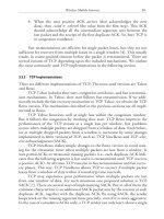
There is a particular interaction between the
steering surface and the support surface, which is
technology dependent and requires specific consideration by the engineer. This interaction results
from a coupling effect which occurs when a vehicle rolls on the primary suspension system, causing the steering mechanism to move up and down
(Fig. 2.7.2.3). The degree of this up and down
movement is dependent on the steering mechanism which is typically an integral part of the
vehicle truck (bogie) system, and the stiffness of
the primary suspension which is also within the
truck assembly.
Depending upon the relationship between the
support and the steering surfaces, and the support
and guidance mechanisms of the vehicle (primary,
in the case of rubber tired system) a couple can be
created between the two, which causes a spurious
steering input into the vehicle. There are no
general specifications for this condition. The
engineer should be aware that this condition can
exist and, if there is a significant distance
separating the horizontal and vertical contact
surfaces, additional tolerance requirements for the
finished surfaces have to be imposed. This is in
order to reduce the considerable steering input,
which can cause over or under steering, which
leads to an accelerated wear of components and
degraded ride comfort.
Table 2.7.2.3 Track Construction Tolerances
Type and Class of Track
-Dimensions are
-H=Horizontal.
-Total Deviation
Sup.=Superelevation
between the theoretical and the actual alignments at any point along
-Variations from theoretical gage, cross level and superelevation are not to exceed l/8 in. (3 mm)
per 15’ -6 (4.7 m) of track.
-The total Deviation in platform areas should be zero towards the platform and l/4 in (6 mm) away
from the platform.
GUIDEWAY STRUCTURES
2.7.3 -Traction Surfaces
Transit vehicles derive their traction from the
physical contact of the wheels with the concrete or
running rail or through an electromagnetic force.
In those systems where traction occurs through
physical contact with the guideway, specific
attention must be given to the traction surface.
In automated transit, the traction between the
wheel and the reaction surface is essential to ensure a consistent acceleration and a safe stopping
distance between vehicles. It is also important for
automatic control functions. The engineer should
determine the minimum traction required for the
specific technology being employed. If the traction surface is concrete, appropriate aggregates
should be provided in the mix design to maintain
minimum traction for the working life of the
structure.
Operation in freezing rain or snow may also
affect traction on the guideway. The engineer
should determine the degree of traction maintenance required under all operating conditions. If
full maintenance is required, then the engineer
should examine methods to mitigate the effects of
snow or freezing rain. These mitigating effects may
include heating the guideway, enclosing the
guideway, or both.
If deicing chemicals are contemplated, proper
material selection and protection must be considered. Corrosion protection may require consideration of additional concrete cover, sealants,
epoxy-coated reinforcing steel, and special concrete mixes.
2.7.4 -Electrical Power Distribution
There are two components to electrical power
distribution: the wayside transmission of power to
the vehicle and the primary power distribution to
the guideway. The wayside power distribution to
the vehicle is normally done through power rails
or through an overhead catenary. Provision must
be made on the guideway for the mounting of
support equipment for the installation of this
wayside power.
For systems using steel running rails, where
the running rail is used for return current, provisions must also be made to control any stray
electrical currents which may cause corrosion in
the guideway reinforcement or generate other
stray currents in adjacent structures or utilities.
The primary power distribution network associated with a guideway may require several substations along the transit route. Power must be
transmitted to the power rails on the guideway
structure at various intervals. This is usually done
through conduits mounted on or embedded in the
guideway structure.
Internal conduits are an acceptable means of
358.1R-11
transmitting power; they may be used to route
power from the substation to the guideway. However, access to internal conduits is difficult to
detail and construct. Sufficient space must be
provided within the column-beam connection and
within the beam section for the conduit turns;
space must also be provided for safe electrical
connections. Exterior conduits can detract from
the guideway appearance and can cause increased
maintenance requirements.
2.7.5 - Special Equipment
A guideway normally carries several pieces of
special transit equipment. This equipment may
consist of switches, signaling, command and control wiring, or supplemental traction and power
devices. The specialty transit supplier should
provide the engineer with explicit specifications of
special equipments and their spatial restrictions.
For example, the placement of signaling cables
within a certain distance of the wayside power
rails or reinforcing steel may be restricted.
The transit supplier should also provide the
engineer with the forces and fatigue requirements
of any special equipment so that proper connections to the structure can be designed and installed. An example of connection requirements
would be linear induction motor reaction rail
attachments.
When no system supplier has been selected, the
engineer must provide for the anticipated services
and equipment. In this instance, a survey of the
needs of potential suppliers for the specific application may be required prior to design.
2.8- Geometries
2.8.1 - General
The geometric alignment of the transit line can
have a substantial impact on the cost of the
system. Standardization of the guideway components can lead to cost savings. During the planning and design stages of the transit system, the
benefits of standardizing the structural elements,
in terms of ease and time of construction and
maintenance, should be examined and the effective options implemented.
2.8.2 -Standardization
Straight guideway can be produced at a lower
cost than curved guideway. Geometric alignments
and column locations that yield a large number of
straight beams tend to be cost-effective. Physical
constraints at the ground influence column locations. However, when choices are available, the
placement of columns to generate straight beams,
as opposed to those with a slight horizontal or
vertical curvature, will usually prove to be more
358.1R-12
MANUAL OF CONCRETE INSPECTION
cost effective.
Standardization and coordination of the internal components and fixtures of the guideway
also tends to reduce overall cost. These include
inserts for power equipment, switches, or other
support elements. Methods to achieve this are
discussed in Section 2.9.3.
2.8.3 -Horizontal Geometry
The horizontal geometry of a guideway alignment consists of circular curves connected to
tangent elements with spiral transitions. Most
types of cubic spirals are satisfactory for the
transition spiral. The vehicle manufacturer may
provide additional constraints on the selection of
a spiral geometry to match the dynamic characteristics of the vehicle.
2.8.4 -Vertical Geometry
The vertical geometry consists of tangent
sections connected by parabolic curves. In most
cases, the radius of curvature of the parabolic
curves is sufficiently long that a transition between
the tangent section and the parabolic section is
not required.
2.8.5 - Superelevation
Superelevation is applied to horizontal curves
in order to partially offset the effect of lateral
acceleration on passengers. To accomplish the required superelevation, the running surface away
form the curve center is raised increasingly relative
to that closer to the curve center. This results in
the outer rail or wheel track being raised while the
inner rail or wheel track being kept at the profile
elevation. The amount of superelevation is a
function of the vehicle speed and the degree of
curvature. It is usually limited to a maximum value
of 10 percent.
2.9- Construction Considerations
2.9.1- General
Construction of the guideway in an urban
environment has an impact on the residents,
pedestrians, road traffic, and merchants along the
route. Consideration should be given to the cost
and length of disruption, in terms of street closure
and construction details.
2.9.2 - Street Closures and Disruptions
The amount of time that streets are closed and
neighborhoods are disrupted should be kept to a
minimum. Coordination with the public should
begin at the planning stage. The selection of
precast or cast-in-place concrete components and
methods of construction depend on the availability
of construction time and on the ease of stockpiling
equipment and finished products at the proximity
of the site. Construction systems which allow for
rapid placement of footings and columns and for
reopening of the street prior to the installation of
beams, may have an advantage in the maintenance
of local traffic.
2.9.3 - Guideway Beam Construction
Guideway beams may be cast-in-place or
precast. In order to ascertain the preferred
construction technique, the following items need
to be considered early in the design process:
typical section and alignment, span composition
(uniform or variable), structure types, span-depth
ratios, and major site constraints.
Cast-in-place construction offers considerable
design and construction flexibility, however, it also
requires a greater amount of support equipment
on the site. This equipment, especially shoring and
falsework, has to remain in place while the
concrete cures.
Precast concrete beam construction offers the
potential for reduced construction time on site and
allows better quality control and assurance.
Advantages of precast concrete are best realized
when the geometry and the production methods
are standardized.
Two types of guideway beam standardization
appear to offer substantial cost benefits. Namely,
modular construction and adjustable form construction.
Modular construction utilizes a limited number
of beam and column types to make up the guideway. Thus, like a model train set, these beams are
interwoven to provide a complete transit guideway.
Final placement of steering surfaces and other
system hardware on the modular elements provides the precise geometry necessary for transit
operation. Modules may be complete beams.
Segmental construction also typifies this construction technique.
An adjustable form allows the fabrication of
curved beams to precisely match the geometric requirements at the site. For alignments where a
substantial amount of variation in geometry is dictated by the site, this solution provides a high
degree of productivity at a reasonable cost.
2.9.4 - Shipping and Delivery
Prior to the completion of final design, the
engineer should be aware of limitations which may
be placed upon the delivery of large precast elements. Weight limitations imposed by local departments of transportation, as well as dimensional
limitations on turnoff radii, width, and length of
beam elements, may play an important role in the
final guideway design. The deployment of large
cranes and other construction equipment along the
site is also a consideration.
GUIDEWAY STRUCTURES
2.9.5- Approval Considerations
These recommendations for transit guideways
are intended to provide procedures based on the
latest developments in serviceability and strength
design. Other pertinent regulations issued by state,
federal, and local agencies should be considered.
Specific consideration should be given to the
following:
-
Alternative designs
Environmental impact statements
Air, noise, and water pollution statutes
Historic and park preservation requirements
Permits
Life-safety requirements
Construction safety requirements
2.9.6 -Engineering Documents
The engineering documents should define the
work clearly. The project drawings should show all
dimensions of the finished structure in sufficient
detail to facilitate the preparation of an accurate
estimate of the quantities of materials and costs
and to permit the full realization of the design.
The contract documents should define test and
inspection methods, as well as the allowable procedures and tolerances to ensure good workmanship, quality control, and application of unit costs,
when required in the contract. The contractor’
s
responsibilities should be clearly defined. Where
new or innovative structures are employed, suggested construction procedures to clarify the
engineer’ intent should also be provided. Coms
puter graphics or integrated data bases can assist
in this definition.
2.10- Rails and Trackwork
2.10.1- General
Guideways for transit systems which utilize
vehicles with steel wheels operating on steel rails
require particular design and construction considerations, which include, rail string assembly, use
of continuous structures, and attachment of the
rails to the structure.
Two options exist for assembling the rails:
They may be jointed with bolted connections in
standard 39 ft. (11.9 m) lengths, or welded into
continuous strings. The rails may be fastened
directly to the structure or installed on tie-andballast.
2.10.2- Jointed Rail
The traditional method of joining rail is by
bolted connections. Sufficient longitudinal rail
movement can develop in these connections to
prevent the accumulation of the thermal stresses
along the length of the rails.
358.1R-13
The space between the rail ends presents a
discontinuity to the vehicle support and steering
systems. Vehicle wheels hitting this discontinuity
cause progressive deterioration of the joints, generate loud noise, reduce ride comfort, and increase the dynamic forces on the structure.
Because of these limitations, most modern transit systems use continuously welded rail. However,
jointed rail conditions will exist in switch areas,
maintenance yards and other locations where
physical discontinuities are required. However,
even in these areas, discontinuities can be reduced
greatly by the use of bonded rail joints.
2.10.3 -Continuously Welded Rail
2.10.3.1 -General
To improve the ride quality and decrease track
maintenance, individual rails are welded into continuous strings. There is no theoretical limit to the
length of continuously welded rail if a minimum
restraint is provided.Minimum rail restraint
consists of prevention of horizontal or vertical
buckling of rails and anchorage at the end of a
continuous rail to prevent excessive rail gaps from
forming at low temperatures, if accidental breaks
in the rail should occur.
Continuously welded rail (CWR) has become
the standard of the transit industry over the past
several decades. The use of CWR requires particular attention to several design details, which
include, thermal forces in the rails, rail break gap
and forces, welding of CWR, and fastening of
CWR to the structure. The principal variables
used in the evaluation of rail forces are rail size in
terms of its cross-sectional area, the characteristics
of the rail fastener, the stiffness of the structural
elements, rail geometry, and operational environment, in terms of temperature range.
In cases where accumulation of the thermal
effects would produce conditions too severe for
the structure, slip joints can be used. Slip joints
allow limited movement between rail strings. They
generally cause additional noise and require increased maintenance. Their use therefore is not
desirable. Location of rail anchors and rail expansion joints will affect the design of the structure.
2.10.3.2 -Thermal Forces
Changes in temperature of continuously welded
rails will develop stresses in the rail and in the
structure. Rails are typically installed at a design
stress-free ambient temperature, to reduce the risk
of rail buckling at high temperatures and rail
breaks at low temperatures. Depending upon the
method of attachment of the rails to the structure,
the structure should be designed for:
- Horizontal forces resulting from a rail break
358.1R-14
-
MANUAL OF CONCRETE INSPECTION
Radial forces resulting from thermal changes
in the rails on horizontal or vertical curves
End anchorage forces
2.10.3.3 -Rail Breaks
Continuously welded rails will, on occasion,
fail in tension. This situation occurs because of rail
wear, low temperature, defects in the rail, defects
in a welded joint, fatigue or some combination of
these effects. The structure should be designed to
accommodate horizontal thrust associated with the
break.
2.10.3.4 -Rail Welding
Continuous welded rail is accomplished by
either the them-rite welding process or the electric
flash butt welding process. Proper weld procedures should ensure that:
-
Adjacent rail heads are accurately aligned
Rails are welded at the predetermined stressfree ambient temperature
Rail joint is clean of debris
The finished weld is free of intrusions
Weld is allowed to cool prior to tightening
the fasteners.
Ultrasonic or x-ray inspection of the welds at
random locations is suggested.
2.10.4 -Rail Installation
2.10.4.1 -General
Rails are attached to either cross ties on
ballast or directly to the guideway structure. The
preference in recent years has become direct rail
fixation as a means of improving ride quality,
maintaining rail tolerances, reducing maintenance
costs, and reducing structure size.
2.10.4.2 -Tie and Ballast
Tie and ballast construction is the conventional method of installing rails at grade and
occasionally on elevated structures. Ties are used
to align and anchor the rails. Ballast provides an
intermediate cushion between the rails and the
structure, stabilizes the tracks, and prevents
thermal forces to be transmitted from the rails to
the structure.
Ballast substantially increases the structure
dead load. Tie-and-ballast installations make
control of rail break gaps difficult since the ties
are not directly fastened to the primary structure.
Rail breaks can develop horizontal, vertical, and
angular displacements of the rail relative to the
structure.
2.10.4.3 -Direct Fixation
Direct fixation of the rail to the structure is
accomplished by means of mechanical rail fastener. Elastomeric pads are incorporated in the
fastener to provide the required vertical and
horizontal flex and provisions for adjustment between adjacent fasteners and the structure. The elastomeric pads also assist in the reduction of noise, vibration, and impact.
Important design and construction considerations for the direct fixation fasteners include:
- Method of attachment to the structure
- Vertical stiffness
- Allowance for horizontal and vertical
adjustment
- Ability to restrain the rail against rollover
- Longitudinal restraint
Direct fixation fasteners are one of the most
important elements in the design of the trackwork. They are subjected to a high number of
cyclic loads and there are thousands of fasteners
in place in any one project. Progressive failure
does not generally create catastrophic results, but
leads to a substantial maintenance effort and
possible operational disruptions.
No industry wide specifications exist for the
definition or procurement of direct fixation fasteners. A thorough examination of the characteristics and past performance of available fasteners, and the characteristics of the proposed
transit vehicle should be undertaken prior to fastener selection for any specific installation.
2.10.4.4 -Continuous Structure
Direct fixation of continuous rail to a continuous structure creates a strain discontinuity at
each expansion joint in the structure. Fasteners
must be designed to provide adequate slip at these
joints while still being able to limit the rail-gap
size in the event of a rail break. In climates with
extreme ranges in temperature [- 40 F to +90 F
(- 40 C to + 30 C)], structural continuity is
generally limited to 200 to 300 ft. (60 to 90 m)
lengths. In more moderate climates, longer runs of
continuous structure may be possible.
REFERENCES*
2.1 ACI Committee 358, “State-of-the-Art Report on
Concrete Guideways,” Concrete Intenational, V. 2, No. 7, July
1980, pp. 11-32.
2.2 Code of Federal Regulations, 49, Transportation, Parts
200-999, Subpart C, Track Geometry, Federal Railroad Administration, Washington, D.C., Section 213.51-213.63.
2.3 National Fire Codes, Publication NFPA - 130, 1983,
Standard on Fixed Guideway Systems, National Fire Protection Association, Battery March Park, Quincy, MA 02269.
358.1R-15
GUIDEWAY STRUCTURES
3.2.2 -Other Sustained Loads
*For recommended references, see Chapter 8.
CHAPTER 3 -LOADS
3.1 -General
The engineer should investigate all special,
unusual, and standard loadings that may occur in
the guideway being designed. Special or unusual
loads may include emergency, maintenance, or
evacuation equipment or conditions. The following loads commonly occur and are considered
when assessing load effects on elevated guideway
structures.3.1
a. Sustained loads
- Dead load
- Earth pressure
- External restraint forces
- Differential settlement effects
- Buoyancy
b. Transient loads
- Live load and its derivatives
- Wind
- Loads due to ice
- Loads due to stream current
c. Loads due to volumetric changes
- Temperature
- Rail-structure interaction
- Shrinkage
- Creep
d. Exceptional loads
- Earthquake
- Derailment
- Broken rail
- Collision loads at street level
e. Construction Loads
- Dead Loads
- Live Loads
Loads from differential settlement, earth
pressure, effects of prestress forces (PS) or external structural restraints should be included in
the design, as they occur. The beneficial effects of
buoyancy may only be included when its existence
is ensured. References 3.2 and 3.11 may be used
as guides to evaluate the effects of these sustained
loads.
3.3 - Transient Loads
3.3.1- Live Load and its Derivatives
3.3.1.1- Vertical Standard Vehicle Loads, L
The vertical live load should consist of the
weight of one or more standard vehicles positioned to produce a maximum load effect in the
element under consideration. The weight and
configuration of the maintenance vehicle are to be
considered in the design. The weight of passengers should be computed on the basis of 175 lb
(780 N) each and should comprise those occupying all the seats (the seated ones) and those
who are standing in the rest of the space that does
not have seats (standees). The number of standees
shall be based on one passenger per 1.5 ft.2 (0.14
m’).
For torsion-sensitive structures, such as
monorails, the possibility of passengers being
crowded on one side of the vehicle should be
considered in the design.
3.3.1.2 -Impact Factor, I
The minimum dynamic load allowance3.2.3.3
shown in Table 3.3.1.2 should be applied to the
vertical vehicle loads, unless alternative values
based on tests or dynamic analysis are approved.
Definition of terms in the Table follow:
vehicle speed, ft/sec (m/sec)
VCF =
(3-l)
span length, ft (m)
fi = first mode flexural (natural) frequency3.4
of the guideway where,
3.2 - Sustained loads
3.2.1 -Dead Loads, D
(3-2)
Four components of dead load are considered:
where
.
.
Weight of factory-produced elements
Weight of cast-in-place elements
Weight of trackwork and appurtenances which
includes running and power rails, second-pour
plinths and fasteners, barrier walls, and noisesuppression panels
Weight of other ancillary components
e
=
span length, center-to-center of
supports, in. (m)
M = mass per unit length of the guideway,
which includes all the sustained loads
the beam carries including its own mass,
lb/in.-sec2/in. (kg/m)
MANUAL OF CONCRETE INSPECTION
358.1R-16
Table 3.3.1.2 Dynamic Load Allowance (Impact)
I
Structure Types
Rubber-tired and
Continuously Welded Rail
Simple-span structures,
> 0.30
_
_
> 0.10
I - - -0.1
- VCF
4
Continuous-span structures,
EC
Ig
VCF
= modulus of elasticity of the guideway,
psi (Pa)
= moment of inertia of uncracked
section of the guideway, in.4 (m4)
= Vehicle Crossing Frequency, Hz
The dynamic load allowance should not be
applied to footings and piles.
3.3.1.3 -Centrifugal Force, CF
The centrifugal force, CF, acting radially
through the center of gravity of the vehicle at a
curved track may be computed from,
CF = f L, WN)
I
> 0.30
_
10.10
I - - -0.1
- VCF
24
(3-3)
where,
= radius of curvature, ft (m)
g = acceleration due to gravity, 32.2 ft/sec/sec
(9.82 m/s2)
V = maximum operating speed of the vehicle,
ft/sec (m/s2) and,
L = the standard vehicle load, kips (kN)
R
The load, L, should be applied simultaneously
with other load combinations (Chapter 4) in order
to produce the maximum force effect on the
structure.
3.3.1.4 -Hunting Force, HF
The hunting (or “nosing”) force, HF, is caused
by the lateral interaction of the vehicle and the
guideway. It should be applied laterally on the
guideway at the point of wheel-rail contact, as a
fraction of the standard vehicle load, L, as follows:
Jointed rail
Bogie type
Nonsteerable
Steerable
Hunting force
0.08L
0.06L
When centrifugal and hunting forces can act
simultaneously, only the larger force need be
considered.
For rail and structure design, the hunting
force would be applied laterally by a steel wheel to
the top of the rail at the lead axle of a transit
train. it need not be applied for rubber tired
systems; typically, LIM propelled vehicles run on
steel-wheel-and-rail and, hence require consideration of hunting effects.
3.3.1.5 - Longitudinal Force, LF
The longitudinal force acts simultaneously
with the vertical live load of a standard vehicle on
all wheels. It may be applied in either direction:
forward in braking or deceleration or reverse in
acceleration. The longitudinal force should be
applied as follows:
Emergency braking, LFe = 0.30L
Normal braking,
LFn = 0.15L
Continuously welded rail trackwork can
distribute longitudinal forces to adjacent components of guideway structures. This distribution
may be considered in design. Use of slip joints
may prevent transfer and distribution of
longitudinal forces.
3.3.1.6 - Service Walkway Loads
Live load on service or emergency walkways
shall be based on 85 psf (4.0 kPa) of area. This
load should be used together with empty vehicles
on the guideway, since the walkway load is the
result of vehicles being evacuated.
358.1R-17
GUIDEWAY STRUCTURES
3.3.1.7-Loads on Safety Railing
The lateral load from pedestrian traffic on
railings should be 100 lb/ft (1.5 kN/m) applied at
the top rail.
2
Fh = the greater of 50 lb/ft (2.4 kPa) or 300
lb/ft (4.4 kN/m)
and
2
Fv = 15 lb/ft (0.7 kPa)
3.3.2 -Wind Loads, W
3.3.2.1 -General
This section provides design wind loads for
elevated guideways and special structures. Wind
loads, based on the reference wind pressure, shall
be treated as equivalent static loads as defined in
Section 3.5.3.
Wind forces are applied to the structure and
to the vehicles in accordance with the load combinations in Chapter 4. WL is used to designate
wind loads applied to vehicle, while WS indicates
wind loads applied to the structure only.
The net exposed area is defined as the net
area of a body, member, or combination of members as seen in elevation. For a straight superstructure, the exposed frontal area is the sum of
the areas of all members, including the railings
and deck systems, as seen in elevation at 90
degrees to the longitudinal axis. For a structure
curved in plan, the exposed frontal area is taken
normal to the beam centerline and is computed in
a similar manner to tangent structures.
The exposed plan area is defined as the net
area of an element as seen in plan from above or
below. In the case of a superstructure, the exposed plan area is the plan area of the deck and
that of any laterally protruding railings, members
or attachments.
The gust effect coefficient is defined as the
ratio of the peak wind-induced response of a
structure, including both static and dynamic action,
to the static wind-induced response.
Buildings and other adjacent structures can
affect the wind forces. Wind tunnel tests may be
considered as a method to improve wind force
predictions or to validate design coefficients in the
alternative design approach provided in Section
3.5.3.
3.3.2.2 - Design for Wind
The guideway superstructure should be designed for wind-induced horizontal, Fh and vertical, Fv drag loads acting simultaneously. The wind
should be considered to act on a structure curved
in plan, in a direction such that the resulting force
effects are maximized. For a structure that is
straight in plan, the wind direction should be
taken perpendicular to the longitudinal axis of the
structure.
The following uniformly distributed load intensities may be used for design:
The wind loads, Fh and Fv, should be applied
to the exposed areas of the structure and vehicle
in accordance with the provisions of sections 4.3
and 4.4.
These loads and provisions are consistent with
the recommendations of the AASHTO Standard
Specifications for Highway Bridges3.11 derived
from wind velocities of 100 mph (160 km/h). Wind
loads may be reduced or increased in the ratio of
the square of the design wind velocity to the
square of the base wind velocity, provided that the
maximum probable wind velocity can be ascertained with reasonable accuracy, or provided that
there are permanent features of the terrain that
make such changes safe and are viable.
The substructure should be designed for
wind-induced loads transmitted from the superstructure and wind loads acting directly on the
substructure. Loads for wind directions both normal to and skewed to the longitudinal centerline
of the superstructure should be considered.
3.3.2.3 -Alternative Wind Load
The alternative wind load method may be
used in lieu of that given in Section 3.3.2.1.
Alternative wind loads are suggested for projects
involving unusual height guideways, unusual gust
conditions, or guideway structures that are, in the
judgment of the engineer, more streamlined than
highway structures.3.7.3.8
The wind load per unit exposed frontal area
of the superstructure, WS, and of the vehicle, WL,
applied horizontally, may be taken as:
Fh = qCeCgCd
(3-4)
Similarly, the wind load per unit exposed plan
deck or soffit area applied vertically, upwards or
downwards, shall be taken as:
qc,cgcd
Fv = qCeCgCd
(3-5)
Where, Cd = 1.0 and Ce, Cg, and q are defined in
Section 3.3.2.4. The maximum vertical wind
velocity may be limited to 30 mph (50 km/h).
In the application of Fv, as a uniformly
distributed load over the plan area of the structure, the effects of a possible eccentricity should
be considered. For this purpose, the same total
load should be applied as an equivalent vertical
358.1R-18
MANUAL OF CONCRETE INSPECTION
line load at the windward quarter point of the
superstructure.
3.3.2.4 -Reference Wind Pressure
The reference wind pressures at a specific site
should be based on the hourly mean wind velocity
of a 75-year return period. A l0-year return
period may be used for structures under construction.
The reference wind pressure, q, may be
derived from the following expression:
(3-6)
where
V
P
g
= mean hourly velocity of wind, ft/sec (m/s)
= density of air at sea level at 32 F (0 C)
= 0.0765 lb/ft3 (1.226 kg/m3)
2
2
= 32.2 ft/sec (9.807 m/s )
For structures that are not sensitive to windinduced dynamics, which include elevated guideways and special structures up to a span length of
400 ft (122m), the gust effect coefficient Cg may
vary between 1.25 and 1.50. For design purposes,
a factor of 1.33 may be used for Cg. For structures that are sensitive to wind action, Cg should
be determined by an approved method of dynamic
analysis or by model testing in a wind tunnel. For
guideway appurtenances, such as sign posts, lighting poles, and flexible noise barriers, Cg may be
taken as 1.75.
The exposure coefficient or height factor, Ce,
may be computed from:
Ce= l/2’
@, 2 l.O,forIiinfl
=5/8’ 2 l.O,forHinm
@,
(3-7)
H is the height from ground level to the top of the
superstructure. It should be measured from the
foot of cliffs, hills, or escarpments when the
structure is located on uneven terrain, or from the
low water level when the structure is located over
bodies of water. Where excessive funneling may be
caused by the topography at the site, Ce should be
increased by 20 percent.
The drag coefficient or shape factor, Cd, is a
function of many variables, the most important of
which are the skew angle (horizontal angle of
wind), and aspect ratio (ratio of length to width of
structure). For box or I-girder superstructures and
solid-shaft piers with wind acting at zero skew and
pitch angles, Cd may vary between 1.2 and 2.0. A
factor of 1.50 for Cd may be used for design purposes. For unusual exposure shapes, the drag coefficient, Cd, should be determined from windtunnel tests.
Where wind effects are considered at a skew
angle of B degrees measured from a line perpendicular to the longitudinal axis of a structure, then
Cd should be multiplied by 0.0078 for the longitudinal wind load component and by (1 - 0.0001813~)
for the transverse or perpendicular load component.
3.3.2.5- Wind Load on Slender Elements and
Appurtenances
Slender elements, such as light and sign
supports, should be designed for horizontal wind
loads provided for in Sections 3.3.2.3 and 3.3.2.4,
as well as lateral and crosswind load effects caused
by vortex shedding. Both serviceability and
strength considerations should be investigated.
Details that may cause stress concentrations due
to fatigue or resonance should be avoided. 3.9
The wind drag coefficient, Cd, for sign and
barrier panels with aspect ratios of up to 1.0, of
1.0 to 10.0, or more than 10.0, should be 1.1, 1.2,
or 1.3, respectively.
For light fixtures and sign supports with
rounded surfaces, octagonal sections with sharp
comers, or rectangular flat surfaces, the values of
Cd should be 0.5, 1.2, or 1.4, respectively. A Value
of 1.2 for Cd should be used for suspended signal
units.
When ice accretion is expected on the surface
of slender components, the total frontal area
should include the thickness of ice.
The dynamic effects of vortex shedding should
be analyzed and the stress limits for 2 x l06 cycles
of loading shall be applied.
3.3.3 -Loads Due to Ice Pressure, ICE
Floating ice forces on piers and exposed pier
caps should be evaluated according to the local
conditions at the site. Consideration should be
given to the following types of ice action on piers
erected in bodies of water:
Dynamic ice pressure due to ice sheets and
ice floes in motion caused by stream or
current flow and enhanced by wind action,
Static ice pressure caused by thermal action
on continuous stationary ice sheets over large
bodies of water,
Static pressure resulting from ice jams at a
guideway site,
Static uplift or vertical loads due to ice sheets
in water bodies of fluctuating level.
Ice loads resulting from freezing rain or con-
GUIDEWAY STRUCTURES
solidation of compact snow on the guideway
superstructure and vehicle should be included, as
appropriate.
available, the structure may be designed for a
minimum temperature rise of 30 F (17 C) and a
minimum temperature drop of 40 F (23 C) from
the installation temperature.
3.3.4- Loads due to Stream Current, SF
3.4.2.2 -Effective Construction Temperature
3.3.4.1 -Longitudinal Loads
The load acting on the longitudinal axis of a
pier due to flowing water may be computed by the
following expression.3.5
SF = ‘ CDAV2y
h
(3-8)
where
A
Y
V
CD
= Exposed area of the pier perpendicular to
the direction of stream flow, ft2 (m2)
= Mass density of water, 62.4 lb/ft3 (1000
kg/m3)
= Speed of stream flow, ft/sec (m/set)
= 0.7 for semicircular-nosed piers
= 0.8 for wedge-nosed piers
= 1.4 for squared-ended piers and against
drift lodged on the pier
3.3.4.2 -Transverse Loads
The lateral load on a pier shaft due to stream
flow and drift should be resolved from the main
direction of flow. The appropriate component
should be applied as a uniformly distributed load
on the exposed area of the pier, below the high
water level, in the direction under consideration.
3.4 -Loads due to Volumetric Changes
3.4.1- General
Provisions should be made for all movements
and forces that can occur in the structure as a
result of shrinkage, creep, and variations in temperature. Load effects that may be induced by a
restraint to these movements should be included
in the analysis. These restraints include those
imposed during construction on a temporary basis
and those imposed by the rail-fastener interaction
on an on-going basis. Effects due to thermal gradients within the section should also be considered.3.5
3.4.3 -Temperature, T
3.4.2.1. -Temperature Range
The minimum and maximum mean daily
temperatures should be based on local meteorological data for a 50-year return period. The range
of effective temperature for computing thermal
movements of the concrete structure should be the
difference between the warmest maximum and the
coldest minimum effective temperatures, which
may be considered to be 5 F (2.5 C) above or
below the mean daily minimum and maximum
temperatures. If local temperature data are not
358.1R-19
If the guideway is to be designed to accommodate continuously welded rails, an effective
construction temperature should be selected. This
temperature, which should be based on the mean
daily temperature prevalent for the locality under
consideration, is used to establish the baseline rail
force.
3.4.2.3 -Thermal Gradient Effects
Curvature caused by a temperature gradient
should be considered in the design of the structure.
The temperature differential between top
and bottom surfaces varies nonlinearly according
to the depth and exposure of the structural
elements and their locality. A winter differential of
15 F (8 C) and a summer differential of 25 F (14
C) between the top of the deck and the soffit of
the structure may be used. The temperature
differential should be increased in regions with
high solar radiation; NCHRP 267 document may
be used as a guide in this respect.3.12
3.4.2.4 -Coefficient of Thermal Expansion
In lieu of a more precise value, the coefficient of linear thermal expansion for normal
weight concrete may be taken as 6.5 x l0-6/deg F
(12 x 10-6/deg C).
3.4.3-Rail-Structure Interaction FR and Fr
Continuously welded rail directly fastened to
the guideway, induces an axial force in the structure through the fastener restraint when the structure expands or contracts due to variations in temperature. Continuously welded rail is assumed to
be installed in a zero stress condition at an effective installation temperature, T0. If the CWR is
installed at a temperature that is different from
the effective installation temperature, then the rail
is physically stressed to be compatible with the
zero stress condition for which it is designed at the
installation temperature.3.6
3.4.3.1 -Thermal Rail Forces
Axial rail stress fr due to a change in the
temperature after installation, is expressed by
fr
= Er a (T1 - T0)
CK
(3-9)
= coefficient of thermal expansion
To = the installation temperature (zero-stress
condition)
358.1R-20
r,
MANUAL OF CONCRETE INSPECTION
= the final rail temperature
E, = modulus of elasticity of rail steel, given in
Section 5.6.3
For a temperature decrease, T1 may be taken
as the minimum effective temperature described in
Section 3.4.2.1. For a temperature rise, T1 may be
taken as the maximum effective temperature plus
20 F (12 C). The corresponding rail force, Fr, is
expressed by:
Fr
=SId;=BA&a(Tl-To)
(3-10)
where Z implies that the forces in all rails should
be summed up. The movement of the structure
through the fasteners induces either a tensile or
compressive axial force on the rail, depending on
whether the temperature rises or drops, respectively, from that at installation.
A vertically or horizontally curved structure
experiences a radial force resulting from the
thermal rail forces. This radial force per unit
length of rail is expressed as
where R is the radius of curvature. FR always
occurs in combination with Fr.
The preceding expressions apply where there
is no motion of the rail relative to the structure.
Where rail motion may occur, the relaxation of
the rail must be analyzed to determine its effect
on the structure. Rail motion may occur when:
-
Rail expansion joints are present or,
Radial or tangential movements of rail and
guideway structure at curves occur, or
A rail break takes place, or
Continuous rails cross structural joints, or
Creep and shrinkage strains in prestressed
concrete elements continue to take place.
3.4.3.2 -Broken Rail Forces
At very low temperatures, the probability of a
rail break increases. The most likely place for a
rail break to take place is at an expansion joint in
the structure. A rail break at this location generally creates the largest forces in the structure.
When the rail breaks, it slips through the
fasteners on both sides of the break until the
tensile force in the rail before the break is
counteracted by the reversed fastener restraint
forces. The unbalanced force from the broken rail
is resisted by both the unbroken rails and the
guideway support system in proportion to their
relative stiffnesses. The probability that more than
one rail will break at the same time is small, and
is generally not considered in the design.
3.4.3.3 - Rail Gap
The relative stiffness of the system should be
proportioned so that the magnitude of the gap between broken rail ends be equal to the maximum
allowable in order to prevent vehicle derailment.
Typically acceptable rail gaps are in the range of
2 in. (50 mm) for a 16-in. (0.4-m) diameter wheel
and up to 4 in. (100 mm) for larger wheels. Rail
gap is controlled by the spacing and stiffness of
the fasteners.
3.4.4 -Shrinkage in Concrete, SH
Shrinkage is a function of number variables,
the most significant of which are the characteristics of the aggregates, the water-cement ratio
of the mix, the type and the duration of curing,
surface-to-volume ratio of the member, the ambient temperature and relative humidity at the
time of placing the concrete. For a major transit
project, shrinkage and creep behavior of the concrete mix should be validated as part of the design
process. For precast members, only the portion of
shrinkage or creep remaining after the element is
integrated into the structure needs to be considered.
In the absence of more accurate data or
method of analysis, shrinkage strain r-days after
casting of normal weight concrete may be
computed from the following expression:3.2
(3-12)
‘ =k&tEshu
sh
where the ultimate shrinkage strain, E&,,, is
expressed as:
[ ( II
H
E* = 55o l - iii6 2
xl04
(3-13)
For 0 I r I 12 in. (300 mm),
k, = 1-S + 0.5,
[
T
where rv is in inches,
i T
1 ‘
,
-300
where rv is in mm.
+ 0.5,
(3-14)
GUIDEWAY STRUCTURES
For rv z= 12 in. (300 mm)
358.1R-21
3.5 - Exceptional Loads
3.5.1 - Earthquake Effects, EQ
kv = 0.5
where rv ,= volume-to-surface-area ratio, t is the
time in days after the end of curing, and H is the
relative ambient humidity, in percent.
k = 1 - e-O.‘
ti
*
(3-15)
3.4.5-Creep in Concrete, CR
Creep is a function of relative humidity,
volume-surface ratio and of time t after application of load. Creep is also affected by the
amount of reinforcement in the section, the
magnitude of sustained prestress force, the age of
the concrete when the force is applied, and the
properties of the concrete mix. If the design is
sensitive to volumetric change, then an experimental validation of creep behavior, based on
the ingredients to be used, may be necessary.
In the absence of more accurate data and
procedure, creep at r-days after application of load
may be expressed in terms of the initial elastic
strain, 6 from:3.2
6 CT = flak
(3-16)
where,
kr = 4.250 - 0.025H
For 0 4 rv I 10 in. (250 mm)
+ 0.7,
(3-17)
where rv is in inches,
I
= 1-z + 0.7,
[ 250 T
where rv is in mm
For rv > 10 in. (250 mm)
k = 0.7
where t is the time in days after application of
load or prestress, and,
k = 1 - e-0.w
f
(3-18)
In regions designated as earthquake zones,
structures should be designed to resist seismic
motions by considering the relationship of the site
to active faults, the seismic response of the soils at
the site, and the dynamic response characteristics
of the total structure in accordance with the latest
edition of AASHTO “Standard Specifications for
Highway Bridges."3.11 Certain local jurisdictions
have Zone 4 high seismic risk requirements for
analysis and design. For structures in this zone, a
dynamic analysis is recommended.
3.5.2 -Derailment Load, DR
Derailment may occur when the vehicle
steering mechanism fails to respond on curves or
when the wheels jump the rails at too large a
pull-apart gap, which may be the result of a break
in a continuously welded rail. Derailment may also
be caused by intervehicle collision. For the design
of the top slab and the barrier wall of the
guideway, both the vertical and horizontal
derailment loads may be considered to act simultaneously.
The force effects caused by a single derailed
standard vehicle should be considered in the design of the guideway structure components. These
effects, whether local or global, should in-clude
flexure, shear, torsion, axial tension or
compression, and punching shear through the
deck. The derailed vehicle should be assumed to
come to rest as close to the barrier wall as
physically possible to produce the largest force
effect. In the design of the deck slab, a dynamic
load allowance of 1.0 should be included in the
wheel loads.
The magnitude and line of action of a horizontal derailment load on a barrier wall is a
function of a number of variables. These include
the distance of the tracks from the barrier wall,
the vehicle weight and speed at derailment, the
flexibility of the wall, and the frictional resistance
between the vehicle and the wall. In lieu of a
detailed analysis, the barrier wall should be
designed to resist a lateral force equivalent to 50
percent of a standard vehicle weight distributed
over a length of 15 ft (5 m) along the wall and
acting at the axle height. This force is equivalent
to a deceleration rate of 0.5 g.
Collision forces between vehicles result from
the derailment of a vehicle and its subsequent
resting position against the guideway sidewall.
358.1R-22
MANUAL OF CONCRETE INSPECTION
This eccentric load on the guideway causes torsional effects, which should be accounted for in
the design. The magnitude and eccentricity of this
vertical collision load is a function of the distance
of the guideway center line from the side wall, the
axle width and the relative position of the center
lines of the car body and the truck after the
collision.
tion should include the weight of workers and all
mobile equipment, such as vehicles, hoists, cranes,
and structural components used during the process
of erection. It is recommended that construction
live load limits be identified on the contract
documents.
3.5.3 -Broken Rail Forces, BR
Forces on the guideway support elements due
to a broken rail are discussed in Section 3.4.3,
under Rail-Structure Interaction.
3.5.4 - Collision Load, CL
Piers or other guideway support elements that
are situated less than 10 ft (3 m) from the edge of
an adjacent street or highway should be designed
to withstand a horizontal static force of 225 kips
(1000 kN), unless protected by suitable barriers.
The force is to be applied on the support element,
or the protection barrier, at an angle of 10 deg
from the direction of the road traffic and at a
height of 4 ft (1.20 m) above ground level. The
Collision Load need not be applied concurrently
with loads other than the dead load of the
structure.
The possibility of overheight vehicles colliding
with the guideway beam should be considered for
guideways with less than 16.5ft (5.0m) clearance
over existing roadways.
3.6 - Construction Loads
3.6.1 -General
Loads due to construction equipment and
materials that may be imposed on the guideway
structure during construction should be accounted
for. Additionally, transient load effects during
construction due to wind, ice, stream flow and
earthquakes should be considered with return
periods and probabilities of single or multiple
occurrences commensurate with the expected life
of the temporary structure or the duration of a
particular construction stage.
3.6.2 - Dead Loads
Dead loads on the structure during construction should include the weights of formwork,
falsework, fixed appendages and stored materials.
The dead weights of mobile equipment that may
be fixed at a stationary location on the guideway
for long durations shall also be considered. Such
equipment includes lifting and launching devices.
3.6.3 -Live Loads
Live loads on the structure during construc-
REFERENCES
3.1 “GOALRT (Government of Ontario Advanced Light
Rail Transit) System Standards - Design Criteria for the
GOALRT Elevated Guideway and Special Structures,
GOALRT Program, Downsview, Part 3, Loads, and Part 4,
Design Methods.
3.2 “OHBD (Ontario Highway Bridge Design) Code,” 3rd
Edition, Ministry of Transportation, Downsview, Ontario 1991,
V. 1 and V. 2.
3.3 Ravera, R.J., and Anders, J.R., “Analysis and
Simulation of Vehicle/Guideway Interactions with Application
to a Tracked Air Cushion Vehicle,” MITRE Technical Report
MTR-6839, The MITRE Corporation, McLean, VA 22101,
Feb. 1975 pp. 95.
3.4 Billing, J.R., “Estimation of the Natural Frequencies
of Continuous Multi-Span Bridges: Report No. RR.219,
Ministry of Transportation, Downsview, Jan. 1979, 20 pp.
3.5 Priestly, M.J.N., and Buckle, I.G., “Ambient Thermal
Response of Concrete Bridges” Bridge Seminar, Road
Research Unit, National Roads Board, Wellington, 1978, V. 2.
3.6 Grouni, H., and Sadler. C.. “Thermal Interaction
Between Continuously Welded Rail and Elevated Transit
Guideway," Proceedings, International Conference on Short and
Medium Span Bridges, Aug. 17-21, 1986, Ottawa, Ont. Canada.
3.7 “National Building Code of Canada” (NRCC 23174),
National Research Council of Canada, Ottawa, 1977, Part 4,
pp. 151-180.
3.8 “Design of Highway Bridges,” (CAN 3-S6), Canadian
Standards Association, Rexdale, 1974.
3.9 Davenport, A.G., and Isyumov, N., “Application of the
Boundary Layer Wind Tunnel to the Prediction of Wind
Loading,” Proceedings, International Seminar on Wind Effects
on Building and Structures (Ottawa, 1967). University of
Toronto Press, 1968, pp. 201-230.
3.10 Davenport, A.G., “Response of Slender Line-Like
Structures to a Gusty Wind,” Proceedings, Institution of Civil
Engineers (London), V. 23, Nov. 1962, pp. 389-408.
3.11 AASHTO, Standard Specification for Highway
Bridges, American Association of State Highway and
Transportation Officials, (Latest Edition).
3.12 NCHRP 267, National Cooperative Highway
Research Program, Washington, D.C., (Latest Edition).
GUIDEWAY STRUCTURES
CHAPTER 4 - LOAD COMBINATIONS AND
LOAD AND STRENGTH REDUCTION
FACTORS
4.1 - Scope
This chapter specifies load factors, strength
reduction factors, and load combinations to be
used in serviceability and strength designs. Structural safety is used as the acceptance criterion.
The derivation of load and strength reduction factors is based on probabilistic methods, using
available statistical data and making certain basic
assumptions.
4.2 - Basic Assumptions
The economic life of a transit guideway is
taken as 75 years. Load and resistance models
were developed accordingly.
Guideway structures should meet the requirements for both serviceability and strength design.
Serviceability design criteria were derived by
elastic analysis; stresses and section resistances
were determined accordingly. Strength design criteria were also derived by elastic analysis. However, while stresses were determined accordingly,
section resistances were determined by inelastic
behavior.
The load and resistance models used in this
study were based on available test data, analytical
results, and engineering judgment.4.2,4.7
Live load is defined by a fully loaded standard
vehicle. The weight of vehicles should include an
allowance for potential weight growth. Resistance
models take into account the degree of quality
control during casting. Thus, the properties of
factory-produced members are considered more
reliable than those of cast-in-place members.
Some requirements for concrete strength control
specified by AASHTO are more stringent than
those specified by ACI. However, ACI specifications are generally assumed in this document.
Safety is measured in terms of the reliability
index. A higher reliability index, reflects a lower
probability of failure. A target reliability index of
4.0 is adopted for strength design. This implies
that a transit structure would have a lower probability of failure than a highway bridge, where a reliability index of 3.5 is commonly used.4.8 The
higher target value is justified by the fact that the
consequences of failure of a transit guideway
would be far greater than those of a highway
bridge. The target reliability index adopted for
serviceability design, is 2.5 for cracking and 2.0 for
fatigue.
The objective in deriving reliability-based load
factors is to provide a uniform safety level to loadcarrying components. The uncertainties in methods of analysis, material properties and dimensional accuracies are taken into account in the
derivation of strength reduction factors. Uncertainties to the magnitude of imposed loads and
their mean-to-nominal ratios are accounted for in
the derivation of load factors. Because of the high
frequency of train passes on a guideway structure,
environmental and emergency loads are combined
with maximum live load. The dead load factor is
set at 1.30 for both precast and cast-in-place components, consistent with the AASHTO bridge specifications and ACI 343R. The derivation of load
and strength reduction factors for other load components is also based on reliability approach.
4.3 - Service Load Combinations
Four service load combinations, S1, S2, S3,
and S4 are listed in Table 4.3. When warranted,
more load combinations may be used on specific
projects. Load and strength reduction factors are
not used for serviceability design.
4.4 -Strength Load Combinations
4.4.1 -General Requirements
For strength design, the factored strength of
a member should exceed the total factored load
effect. The factored strength of a member or cross
section is obtained by taking the nominal member
strength, calculated in accordance with Chapter 6,
and multiplying it by the appropriate strength
reduction factor 4, given in Section 4.4.3. The
total factored load effect should be obtained from
relevant strength combination, U, incorporating
the appropriate load factors given in Table 4.4.
Simultaneous occurrence of loads is modeled
by using available data. For the purposes of reliability analysis, loads are divided into categories
according to their duration and the probability of
Table 4.3 - Service load combinations
Sl = D + L + I +PS + LF, + (CF or HF or F()
S2 = Sl + [03 (WL + WS) or ICE or SF]
S3 = S2 + T + SH + CR
S4=PS+D+(WSorEQ)+T+SH+CR
358.1R-23
358.1R-24
MANUAL OF CONCRETE INSPECTION
.
load combinations
Load component
U0
Ul
U2
U3
U4
U5
U6
D
1.3*
1.3*
1.3*
1.3*
1.3*
1.3*
1.3*
L, I and either CF or HF
1.7
1.4
1.4
1.4
1.4
1.4**
SH and CR
1.0
1.0
1.0
1.0
1.0
1.0
PS
1.0
1.0
1.0
1.0
1.0
1.0
WL + WS
1.5
1.0
1.5
1.0
WS
ICE, T, SF, or EQ
1.5
LFe
1.4
BR (FR, FJ
l.2
CL
1.3
DR
l
l
1A
Use 0.9 when effect is more conservative.
* Use the weight of an empty train only.
4.4.2 -Load Combinations and Load Factors
their joint occurrence, as follows:
-
Permanent loads: dead load, earth pressure,
structural restraint
- Gradually varying loads: prestressing effects,
creep and shrinkage, differential foundation
settlement, and temperature effects
- Transitory loads: live load (static and
dynamic) and wind,
- Exceptional loads: earthquake, emergency
braking, broken rail, derailment, vehicle
collision
It is assumed that gradually varying loads act
simultaneously with permanent loads. ‘
The former
are taken at their maximum or minimum level,
whichever yield the worse case scenario for structural performance, for the duration considered.
Transitory and exceptional loads are combined
according to Turkstra’ rule. 4.9 This rule stipulates
s
that the maximum total load occurs when one of
the load components is at its maximum value, simultaneously with the other load components
taken at their average values. Ail possible combinations are considered in order to determine the
one which maximizes the total effect. The load
factors corresponding to the time-varying load
combinations reflect the reduced likelihood of
simultaneous occurrence of these loads.
Load combinations, together with the corresponding factors for strength design, are listed in
Table 4.4. Values of load components are specified in Chapter 3.
4.4.3 - Strength Reduction Factors,
o
l
The capacity of a section should be reduced
by a strength reduction factor, 4, as follows:
-
For flexure only, or flexure with
o = 0.95
l
axial load in precast concrete
For flexure only, or flexure with
o = 0.90
l
axial load in cast-in-place concrete
For shear and torsion
o = 0.75
l
For axial tension
f#J = 0.85
For compression in members
with spiral reinforcement
4 = 0.75
For compression in other members 6 = 0.70
For low values of axial compression, 4 may be
increased linearly to 0.90 or 0.95 for cast-in-place
or precast concrete, respectively, as the axial load
decreases from 0.10 f,’ Ag to zero.
The o factors were computed with the asl
sumption that precast concrete guideway components, with bonded post-tensioning tendons are
used.
358.1R-25
GUIDEWAY STRUCTURES
REFERENCES*
b.
4.1 Corotis, B., “Probability-Based Design Codes,"
Concrete International Design and Construction, V. 7, No. 4,
Apr. 1985, pp. 42-49.
4.2 Nowak, A.S., and Grouni, H., “Serviceability
Consideration for Guideways and Bridges,” Canadian Journal
of Civil Engineering, V. 15, No. 4, Aug. 1988, pp. 534-538.
4.3 Grouni, H.N., Nowak, A.S., Dorton, R.A., “Design
Criteria for Transit Guideways," Proceedings, 12th Congress,
International Association for Bridge and Structural
Engineering, Zurich, 1984, pp. 539-546.
4.4 Nowak, A.S., and Grouni, H.N., “Development of
Design Criteria for Transit Guideway," ACI JOURNAL,
Proceedings V. 80, No. 5, Sept.-Oct. 1983, pp. 387-389.
4.5 Nowak, A.S. and Grouni, H.N., “Serviceability Criteria
in Prestressed Concrete Bridges,” ACI JOURNAL, Proceedings
V. 83, No. 1, Jan.-Feb. 1966, pp. 43-49.
4.6 Thoft-Christensen, P., and Baker, MJ., Structural
Reliability Theory and Its Applications, Springer-Verlag, New
York, 1982, 267 pp.
4.7 Nowak, A.S., and Lind, NC, “Practical Bridge Code
Calibration,” Proceedings, ASCE, V. 105, STl2, Dec. 1979, pp.
2497-2510.
4.8 “OHBD (Ontario Highway Bridge Design) Code,” 3rd
Edition, Ministry of Transportation, Downsview, Ontario, 1991,
V. 1 and V. 2.
4.9 Turkstra, C.J., “Theory of Structural Design
Decisions,” Study No. 2, Solid Mechanics Division, University
of Waterloo, Ont., 1970, pp. 124.
*For recommended references, see Chapter 8.
CHAPTER 5- SERVICEABILITY DESIGN
5.1 - General
This chapter covers the performance of
reinforced concrete guideways (both prestressed
and non-prestressed) under service loadings.
Serviceability requirements to be investigated
include stresses, fatigue, vibration, deformation
and cracking.
Fatigue is included in serviceability design
since high cyclic loading influences the permissible
design stresses. Load combinations for serviceability design are given in Section 4.3. Durability
considerations are given in Section 2.3.6.
5.2 - Basic Assumptions
Force effects under service loads should be
determined by a linear elastic analysis. For
investigation of stresses at service conditions, the
following assumptions are made:
a. Strains are directly proportional to distance
c.
from the neutral axis
At cracked sections, concrete does not resist
tension
Stress is directly proportional to strain.
5.3 - Permissible Stresses
5.3.1 - Non-prestressed Members
Fatigue and cracking are controlled by limiting the stress levels in the concrete and the nonprestressed reinforcement. The stress limitations
are discussed in Sections 5.5 and 5.8.
5.3.2 - Prestressed Members
5.3.2.1 -Concrete
Flexural stresses in prestressed concrete members should not exceed the following:
(a) At transfer:
Stresses before losses due to creep, shrinkage
and relaxation and before redistribution of force
effect take place, should not exceed the following:
- Compression
l pretensioned members:
l post-tensioned members:
0.60fci’
0.55fci'
- Tension in members without bonded
nonprestressed reinforcement in the
0.4Of,
tension zone:
In the absence of more precise data, the
cracking stress of concrete, f,., may be
taken as 7.5 ,& (psi) (0.6 & MPa).
- Tension in members with bonded nonprestressed reinforcement in the tension
l.OOf,,
zone:
Where the calculated tensile stress is
between 0.4Of, and l.Of=,+ reinforcement should be provided to resist the
total tensile force in the concrete
computed on the basis of an uncracked
section. The stress in the reinforcement
should not exceed 0.6Of or 30 ksi (200
MPa), whichever is smaller.
- Tension at joints in segmental members:
0 Without bonded non-prestressed
reinforcement passing through the joint in
0.0
the tension zone: